question

mvader (Victron Energy) avatar image
mvader (Victron Energy) asked

Venus OS v2.60~33 available for testing

And hello again everyone!

Another v2.60 test version, v2.60~33 to be specific.

This post is intended for all people participating in the Venus OS Beta test program.

In case you're new to the v2.60 beta test series, please make sure to read the previous v2.60 posts, listed below. There are several significant improvements in v2.60. The highlights are the addition of a feed-in limit, added ethernet-connected energy meters, updates on the NMEA2000-feature (addition of tanks, and Solar chargers), as well as many other improvements with regards to tank monitoring.

Complete change log is still on its way.


What to test & how to report?

The updated Marine MFD HTML5 App need testing. Especially on different size MFDs & system configurations.

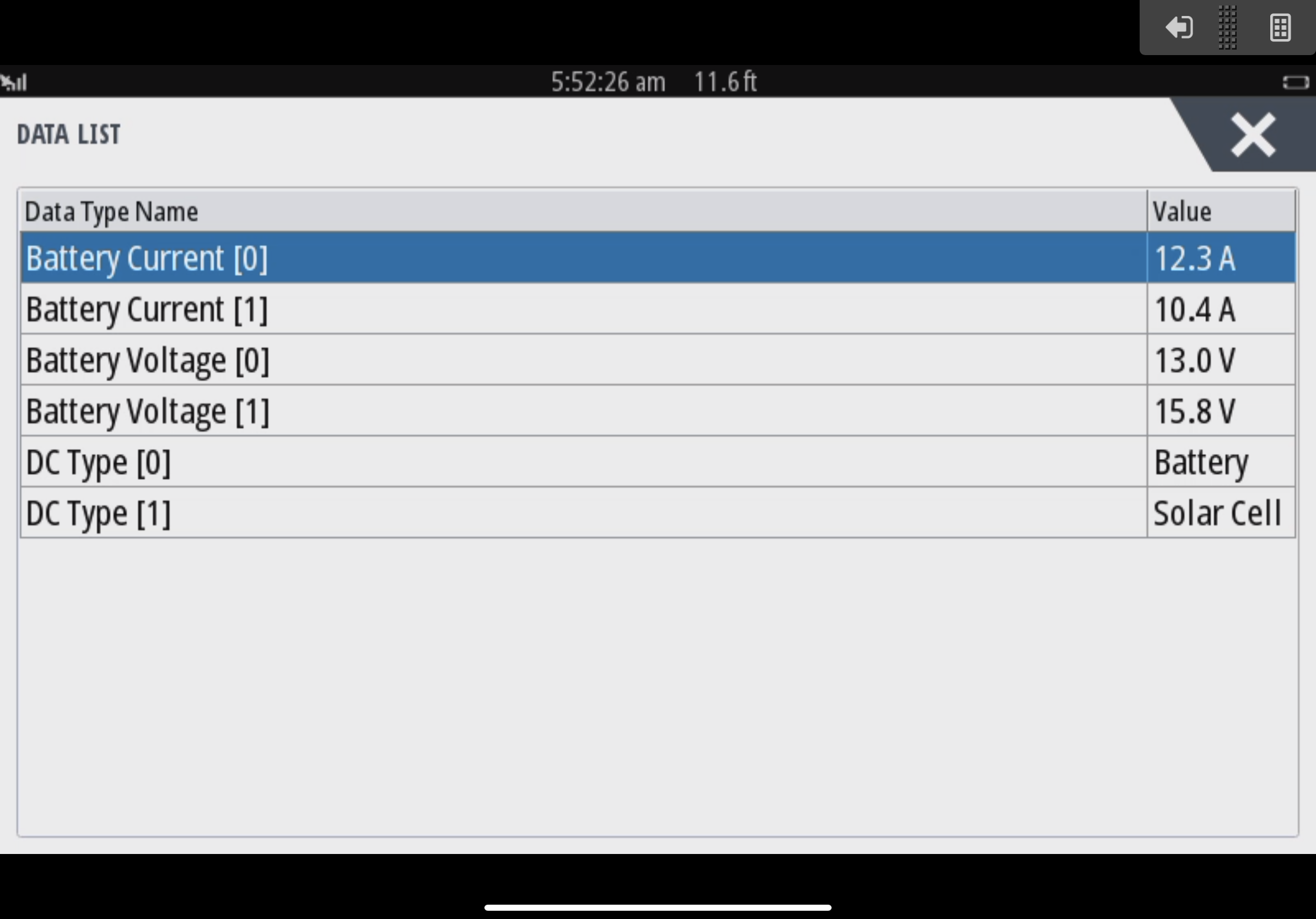
Also the user interface improvements around NMEA2000-out & VE.Can/N2K Device Instance configuration would be good if they are tested. New in this release is automatic numbering of the N2K data instances for tank levels; see below for details.

If you see issues, please post a new "answer" below; or in case the same issues is already mentioned, then comment on that to say you see it too; or help, and so forth. Please do mention the Venus OS version you have installed; just to prevent confusion.


Change log v2.60~32 & v2.60~33

  • Fix false grid alarm triggered by safety switch Assistant (thank you Mark!)
  • Marine MFD HTML5 App: improve battery metric dynamic resizing
  • Modbus-TCP - Add registers related to ESS features. Details are already documented in the ESS Mode 2 & 3 manual.
  • Modbus-TCP - Add 32-bit register for generator runtime (3504). Thank Dave J. for reporting.
  • DVCC: Fix false insufficient firmware alarm triggered for certain VE.Can MPPTs.


Thank all of you for your help, its paramount to getting to a stable and robust yet continuous improving product.

Have a good night, Matthijs Vader

Venus OS
2 |3000

Up to 8 attachments (including images) can be used with a maximum of 190.8 MiB each and 286.6 MiB total.

5 Answers
pleriche avatar image
pleriche answered Ā·

Hi,

Starting on 2.60~4, the charge voltage for Pylontech batteries was increased from 52.0V to 52.4V. (https://github.com/victronenergy/venus/issues/536 ) I'm now regularly seeing a SOC of 99% and 100%, which is great. However, if you also have feeding in of excess DC enabled then the charge voltage is bumped an additional 0.4V. At 52.8V I'm seeing high voltage alarms from the BMS on an almost daily basis. It appears that the Pylontechs store so little energy above 52V that even the slightest imbalance leads to a sufficient difference in cell voltage to cause such an alarm.

It's possible that I've got particularly finicky batteries, so more data points are probably needed, but if that is not the case then perhaps a solution could be to drop the charge voltage on Pylontechs back to 52.0V *only* when feeding in excess DC (to allow for the 0.4V offset to bring it up to 52.4V). 52.4V seems to be the sweet spot for Pylontechs: Lower and you don't get 100% SOC, higher and "high voltage" warnings from the BMS become likely.

I should add that I am also making use of the new feature to limit the grid export, and I have it set to a fairly low value: 500W (on my 5kVA Multiplus II). If I take off the limit and allow it to push the full excess onto the grid then the charge voltage drops back down to the region of 52.3V/52.4V.

Best regards,

Pierre

6 comments
2 |3000

Up to 8 attachments (including images) can be used with a maximum of 190.8 MiB each and 286.6 MiB total.

mvader (Victron Energy) avatar image mvader (Victron Energy) ā™¦ā™¦ commented Ā·

Hi Pierre, thats good feedback! Thank you. Weā€™ll look into that.

0 Likes 0 Ā·

Hi @pleriche,

Pylontech's documentation actually calls for a charge voltage between 52.5V and 53.5V and you should not be getting high voltage warnings if the battery is properly balanced internally. We deliberately operate at the lower end of that scale already. You can also read up the reasoning behind the very slight voltage increase here:

https://github.com/victronenergy/venus/issues/536

We have a few other Pylontech sites also running v2.60 without the same issues, so this appears to be specific to your battery. I will contact you so we can look into this in more detail.

0 Likes 0 Ā·
bottemlesspits avatar image bottemlesspits Izak (Victron Energy Staff) ā™¦ā™¦ commented Ā·

I have also noticed the higher voltage of 52.8V on my system when Keep charged is enabled , but Normal operation(without battery life) i see 52.4-52.5

But since i added 2 more pylons just as this update pushed out i ignored the battery high voltage as my bank needs to balance to my opinion.

Feed in excess is not enabled.

Ill do a roll back on firmware and see if a previous version also has this issue. will do a update here with my findings


0 Likes 0 Ā·
bottemlesspits avatar image bottemlesspits bottemlesspits commented Ā·

Issue seems fixed in version ~ 35 will check today again winter is not the best time to try and get battery full

0 Likes 0 Ā·
pleriche avatar image pleriche commented Ā·

Just an update on this: It was indeed a faulty battery. I have not had any high voltage warnings since the battery was exchanged. Thanks @Izak (Victron Energy Staff) for your help.

0 Likes 0 Ā·
mvader (Victron Energy) avatar image mvader (Victron Energy) ā™¦ā™¦ pleriche commented Ā·

Thats good to hear and thank you for letting us know @pleriche

0 Likes 0 Ā·
matthias-roetzer avatar image
matthias-roetzer answered Ā·

Hi,

So far I really like the new features of V2.6, the configuration options are far better organized on the screen than in the previous versions.

But however I've recognized two important issues when using ESS, at least very important for me :) These occur in the beta v2.60~30 and older releases as well. The recent beta I still have to test, but I guess it's unchanged.

1st: It is possible to create a deadlock situation on/from the SOC calculation.

2nd: DC PV excess feed in reduces MPPT power to a few Watts although enough sun power is available. This is related to the additional 0,4V mentioned as well by Pierre!

Would you like to discuss this here or in a completely separate thread, as it is not fully beta specific?

Best regards,

Matthias


15 comments
2 |3000

Up to 8 attachments (including images) can be used with a maximum of 190.8 MiB each and 286.6 MiB total.

mvader (Victron Energy) avatar image mvader (Victron Energy) ā™¦ā™¦ commented Ā·

Hi Matthias, discussing here is fine - could you elaborate on both points? Ie for 1: how do you get the deadlock?


and 2: under what exact settings / situation to you expect the mppt to product power while now it doesnā€™t?

0 Likes 0 Ā·
matthias-roetzer avatar image matthias-roetzer mvader (Victron Energy) ā™¦ā™¦ commented Ā·

Hi Matthijs,

ok, then, here is the system layout on which I have recognized the two issues.

the GEL battery from Hoppecke has the following settings inside ESS Assistant (3xMultiplus II)

float: 54,0V

Absorption 57,6V

0 Likes 0 Ā·
1594965095567.png (913.3 KiB)
1594965258532.png (1.9 KiB)
1594965330405.png (936.7 KiB)
matthias-roetzer avatar image matthias-roetzer mvader (Victron Energy) ā™¦ā™¦ commented Ā·

How to create SOC deadlock while in grid parallel mode

My implemeted energy management tries to use solar power when available and on the other hand keeping the batteries almost full whenever possible.

This will keep the system in FLOAT state and a slowly decreasing SOC over time! see green arrow!

Because the consumption from the battery is low, the reBULK condition is not met.

In time the configured minimum SOC value (uper blue mark) will be reached and the system goes to SUSTAIN mode.

The battery will not be further discharged, but isn't charged much as well because it will charge only until the FLOAT voltage which is 54,0V in my case. The SOC is not increased, nor decreased, maybe only a few percent range. --> DEADLOCK

To escape the situation I lowered the minimum SOC value (middle blue mark).

Afterwards the same behaviour reoccured at lower SOC.

When lowering the SOC a third time (lowes blue mark) I intenionally applied a high load to the system to trigger the reBULK condition.

After that the battery is beeing charged in BULK and ABSORPTION (57,6V in my case), see orange arrow.

The SOC jumped from about 60% to 95% which means the SOC calculation deviated about 35% from the real physical SOC.

I've created such deadlock situations several times, even with SOC jumps from 20 to 95%.

I've not yet tested what will happen in island mode when the shutdown SOC is reached. But could be interesting!


Suggestion on how to avoid / escape SOC deadlock

  • Improve SOC calculation for low consumption from battery. Better matching of calculated and physical SOC will avoid the deadlock. This could be eg done by configuring a charging/discharging efficency curve.
  • Implement a "deadlock safety escape mechanism": when going to SUSTAIN mode trigger BULK immediately.
  • Another option is to aggressively modify the general reBULK condition, but that's not the preferred way because it will cause ABSORPTION charge too often!
0 Likes 0 Ā·
1594966779486.png (161.0 KiB)
mvader (Victron Energy) avatar image mvader (Victron Energy) ā™¦ā™¦ matthias-roetzer commented Ā·

Hi @Matthias Roetzer, for the SOC deadlock issue I'm not sure how to solve it and if there is a way to properly solve it.

I'll respond to your two suggestions:

1) SOC calculation improving is rather difficult. Going into curves etcetera would be maybe nice for your system, but too theoretical for most. Thinking about it, you could buy a BMV, it measures more accurately than the Multi itself.

> The SOC jumped from about 60% to 95% which means the SOC calculation deviated about 35% from the real physical SOC.

No, that doesn't mean that. It just means that the conditions to set the SOC to 95% where met. What the actual state of charge was/is at that point remains a guess.

There are only two absolute truths when it comes to battery SOC, and that is by fully charging them: when voltage is high, and current is (near) zero, the battery is full. By definition. And the other way is on OPzS batteries, measuring specific gravity of the acid.

2) Sustain levels are chosen low enough to not charge the battery - (on purpose! many systems don't want to charge their battery from the grid unless absolutely necessary) - and high enough to ensure that they are not too empty either - to prevent (too much) damage to a lead battery when left in partial state of charge. So, going into bulk immediately is not a solution.


I'll keep it in mind though, a deadlock is ofcourse not good. There is a way to get out of it - its when there is enough sun again. For periods without enough sun, we often advice to set the ESS mode of the system to Keep batteries charged. Especially for lead battery systems like yours, to prevent unnecessarily shortening the battery life time.


0 Likes 0 Ā·
matthias-roetzer avatar image matthias-roetzer mvader (Victron Energy) ā™¦ā™¦ commented Ā·

Hi @mvader (Victron Energy)

Many thanks for your most appreciated answer! I sense some possible misunderstanding maybe because of wording but I'm not sure yet. However I appreciate if you could give some short clarification on the below.

>No, that doesn't mean that. It just means that the conditions to set the SOC to 95% where met.

True, I agree in principle, but in my case the battery was always indeed full shortly after as I could see by decreasing battery power. So the jump does indeed represent a deviation, but ofc this is has som uncertainty speaking of nn% SOC.

>There are only two absolute truths when it comes to battery SOC, and that is by fully charging them: when voltage is high, and current is (near) zero, the battery is full. By definition. And the other way is on OPzS batteries, measuring specific gravity of the acid.

I totally agree, but please consider my above comment.

> I'll keep it in mind though, a deadlock is ofcourse not good. There is a way to get out of it - its when there is enough sun again. For periods without enough sun, we often advice to set the ESS mode of the system to Keep batteries charged. Especially for lead battery systems like yours, to prevent unnecessarily shortening the battery life time.

Please let me have your clarification on that.

a) does it mean you suggest setting "keep batteries full" to avoid the deadlock

or (maybe and)

b) does it mean you are saying enough sun will automatically force the system to escape the deadlock? In this case I would have to describe the deadlock better because it's not possible to escape it this way automatically as far as I have investigated this. (Maybe after sustain time, but I was never patient enough to wait for that :).

2) Sustain levels are chosen low enough to not charge the battery - (on purpose! many systems don't want to charge their battery from the grid unless absolutely necessary) - and high enough to ensure that they are not too empty either - to prevent (too much) damage to a lead battery when left in partial state of charge.

As far as I understand what you want to express, I can say I totally agree on the above 2)

So, going into bulk immediately is not a solution.

But frankly, I don't understand why "not bulking" is your conclusion!

For clarification, when I'm talking about BULK, I mean bulk from solar and definitely NOT bulk from grid. So why would I ever like not to charge a battery from solar when beeing in sustain? Sorry to say, but I don't get it!

Off Topic: when thinking about NiCd, a sustain mode would be somehow inversed to the one of lead battery. But let us avoid extending the issue here now.

Best regards,

Matthias


0 Likes 0 Ā·
mvader (Victron Energy) avatar image mvader (Victron Energy) ā™¦ā™¦ matthias-roetzer commented Ā·

Hi @Matthias Roetzer, took a while to answer here again, sorry for the silence.

I read above all again. Perhaps indeed we should make sure that the Inverter/charger changes its system state to Bulk when it goes into Sustain (in an ESS system, the inverter/charger is managing the charger states, the MPPT is downgraded to "execution only").

I'll discuss this internally - but that might quite a while, available resources on inverter/charger development & support are small compared to the number of requests.

In the interim, one solution might be to get yourself a BMV battery monitor, it does its state of charge calculation in a different way. But you'll have to try that to see if it helps - no promises.

Sorry I can't help any better now.

best regards, Matthijs


Ps. in your first email, you wrote "In time the configured minimum SOC value (upper blue mark) will be reached and the system goes to SUSTAIN mode. ". I think it works a bit different. Sustain is a feature in the inverter/charger, and isn't triggered by state of charge. See here for how the system enters Sustain: https://www.victronenergy.com/live/ess:design-installation-manual#sustain_mode.


0 Likes 0 Ā·
mvader (Victron Energy) avatar image mvader (Victron Energy) ā™¦ā™¦ mvader (Victron Energy) ā™¦ā™¦ commented Ā·

ps. I'll close this v2.60 beta thread now. Perhaps indeed a separate question would have been better to start this with - anyway if you have further discussion on this, please make a new question.

0 Likes 0 Ā·
matthias-roetzer avatar image matthias-roetzer mvader (Victron Energy) ā™¦ā™¦ commented Ā·

Hi @mvader (Victron Energy)

No need to be sorry! I can imagine your workload :)

Meanwhile I've started to play around with the inverter setup parameter "charge efficiency". Looks like it can affect the behaviou at least a little bit to the better, at least delay it. Next try is to raise the value above 1 and see what happens. (crazy me :)

using BMV is the last option which I keep in mind.

regarding "sustain" yes, I suspect there is a misunderstanding because of the wording. I'll report that better on the next occurence of the issue!

Best regards,

Matthias


0 Likes 0 Ā·
matthias-roetzer avatar image matthias-roetzer mvader (Victron Energy) ā™¦ā™¦ commented Ā·

Hi @mvader (Victron Energy)

just had aother idea this morning how to solve the SOC deadlock:

Obviously you don't like the rebulk safety switch idea, but what if you implement another condition for setting SOC to a specific value like:

when battery power / battery current on charging drops below eg C/20 while in continous voltage limitation at FLOAT or ABSORPTION set the SOC to the configurable value eg. 95% unless it isn't already higher at that time.

in my case that would mean C=460Ah --> C/20=23A --> 1242W at float and 1324W at absorption. --> set to 95%. --> deadlock avoided.

Best regards,

Matthias


0 Likes 0 Ā·
matthias-roetzer avatar image matthias-roetzer mvader (Victron Energy) ā™¦ā™¦ commented Ā·

DC PV excess power feed in issue

In my case 48V lead GEL battery with FLOAT 54,0V; ABSORPTION 57,6V

The system will set the target charge voltage inside the MPPT to either the above values or 0,4V higher, so 54,4V or 58,0V. See the screenshots below.

While the target voltage is raised by 0,4V the DC feed in works perfectly.

When the target voltage is not raised, the DC feed in does not work at all. The MPPT power is reduced sometimes even to a few Watts.

The changes between raised and not raised level are frequent, every few minutes or maybe even seconds. But thats more subjective because I've not tracked the level changes frequency in very detail.

The graph below shows only DC PV power. The chart was taken from an all sunny day, no clouds at all. So the curve should be nicely GAUSS like (blue), but it isn't due to the above described behaviour.

Moreover, when the target voltage is not raised, AC PV power is given priority over DC PV power to charge the battery! That means as long as excess AC PV power is available, it will be used to charge the batteries and possible DC power is lost until the target voltage is raised.

I've played a lot with settings (DVCC, SVS, STS, ...) in every possible combination, but didn't change the behaviour.

Why the target voltage changes so frequently, I don't have a clue so far.

What I subjectively can tell is, that the changes occur more frequently if there are frequent load changes as well. And the occurence is less often if there is almost no load or stable load.

I definately want to track that issue down to the bottom, but what I'm wondering now is, do I have the means on hand to do so? Please suggest! I'm prepared to gather all data and carry out all tests that you need to narrow it down! I really want to get rid of this because its a very annoying issue when you loose environmental friendly PV kWh.

However I've found a solution to escape this behaviour, but it is not a preferred solution, because I loose data visualization partially. When I disconnect the data cables (VEdirect) between the MPPT and the GX, and set the charge voltages inside the MPPT higher (0,1V is sufficent) than the settings in the MultiPlus, DC feed in always works!

The following suggestion of improvement came to me as a byproduct of the above issue:
Implement a safety voltage configuration option inside the MPPT for which an override by external control is not possible! In my configuration I have seen one time a target voltage of 61.6V by external control which is definately far too high for my batteries and I don't have a clue where it came from! I would like to set the safety voltage eg to 58V which must not be exceeded!


0 Likes 0 Ā·
1594968572921.png (247.7 KiB)
1594968588526.png (247.8 KiB)
1594970744033.png (107.4 KiB)
1594971630403.png (250.0 KiB)
mvader (Victron Energy) avatar image mvader (Victron Energy) ā™¦ā™¦ matthias-roetzer commented Ā·

Hi @Matthias Roetzer, for the "DC PV excess power feed in issue " , update firmware in the inverter/chargers as well as update the ESS Assistant.


Most likely that solves it.


best regards, Matthijs

0 Likes 0 Ā·
matthias-roetzer avatar image matthias-roetzer mvader (Victron Energy) ā™¦ā™¦ commented Ā·

Hi @mvader (Victron Energy),

The MPPT were already running currently newest firmware (V1.50).

The GX is running 2.60~34.

Just the ESS assistant was not the very newest. I definitely updated several times the ESS as well and at least once this year, while investigation this issue.

However, ESS is newest now as of today. I'll report again.

Best regards,

Matthias

0 Likes 0 Ā·
mvader (Victron Energy) avatar image mvader (Victron Energy) ā™¦ā™¦ matthias-roetzer commented Ā·

Hi Matthias, the inverter/charger is at 459. You'll need to update that as well.


(and I know thats a bit of work due to reconfiguration required - sorry for that).


0 Likes 0 Ā·
matthias-roetzer avatar image matthias-roetzer matthias-roetzer commented Ā·

Hi, @mvader (Victron Energy)

PV excess feed in looks good now.

It seems the last ESS update did it.

Thank you!

Best regards,

Matthias

0 Likes 0 Ā·
mvader (Victron Energy) avatar image mvader (Victron Energy) ā™¦ā™¦ matthias-roetzer commented Ā·

ok good - thank you for confirming.

0 Likes 0 Ā·
chuff avatar image
chuff answered Ā·

Hi, some correction to do in the digital input alarm on the venus os (sorry if it is not here to do request: i have connected the relay alarm of the Battery Balancer to one digital input of the venus GX. When the battery balancer power on during the day (following charge process of the charger), the battery balancer start with a power on stage where the alam relay come on for 1s. In this case the venus OS detect the alarm and send a false notification on the console screen.

My idea is to add a "confirm delay" in the digital alarm notification that use can parameter thru the gui. That could be also use globally for all type of alarm to avoid detection of false alam...


1 comment
2 |3000

Up to 8 attachments (including images) can be used with a maximum of 190.8 MiB each and 286.6 MiB total.

mvader (Victron Energy) avatar image mvader (Victron Energy) ā™¦ā™¦ commented Ā·

Hi @chuff yes I can see how that would be a nice extra feature for the digital inputs - weā€™ll keep it in mind for future improvements.

Thank you!

0 Likes 0 Ā·
pappajj avatar image
pappajj answered Ā·

Is there any way to install packages using sudo with the raspberry pi venus? I'd like to install a controller for my pi4 cooling fan..!

1 comment
2 |3000

Up to 8 attachments (including images) can be used with a maximum of 190.8 MiB each and 286.6 MiB total.

mvader (Victron Energy) avatar image mvader (Victron Energy) ā™¦ā™¦ commented Ā·

hi, yes you can look into opkg. But please discuss that in a new question - its off topic for this field testing process - thank you!

0 Likes 0 Ā·
bene avatar image
bene answered Ā·

I'm running v2.60~33 on my boat and it was nice see my MPPT 100/30 show up over NMEA 2000. The screens below are from the Settings/Network/Devices section on a Simrad GO5.

Unfortunately I have not yet been able to display values like Solar Cell voltage and current in data display windows, but I think it's an issue with source selection in the Simrad OS (which just got a big update, especially around instrument displays). Or it may be because of conflicting Instance numbers, which still confuse me a lot.


1 comment
2 |3000

Up to 8 attachments (including images) can be used with a maximum of 190.8 MiB each and 286.6 MiB total.

mvader (Victron Energy) avatar image mvader (Victron Energy) ā™¦ā™¦ commented Ā·

Hi @BenE, sorry for the late reply, Summer holidays and all here.

Those instance numbers can be confusing indeed. One thing that might help you is that we recently tried all data in detail on Simrad, Garmin, and Raymarine MFDs. Results / testing-notes are added to a NMEA2000 chapter in the respective manuals. See Garmin, Simrad, and so forth links here:


https://www.victronenergy.com/media/pg/2556-GX_Device_Manual_CCGX/en/marine-mfd-integration-by-app.html#UUID-937e3f30-d245-b5e8-49c2-61e5d7c2776e


If you still have questions, welcome to post a separate question about this. I'll close this v2.60 beta thread now.


0 Likes 0 Ā·

Related Resources