Hi,
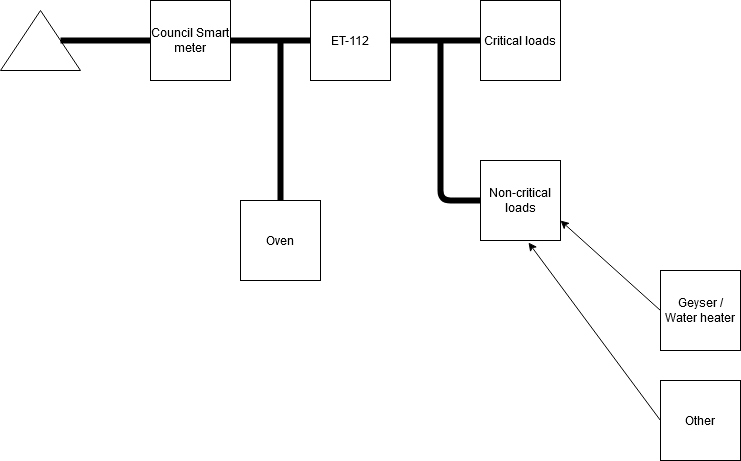
Recently I've installed ET112 grid meter on my system (which was using CT sensor previously) and I've noticed that the Multi is very slow on response to load. Currently my system looks like this:
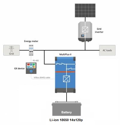
The grid set point is set to -10W. The multi needs a good 15-18 seconds to stabilize after large load kicks in and another approx 15s to stabilize after load drops off. Check the video from VenusGX (the load is switched on at about 16s of the clip and switched of at 43s of the clip):
Is that how it should be? The difference in the load is just about 1.4kW, why is it taking so long to handle that?
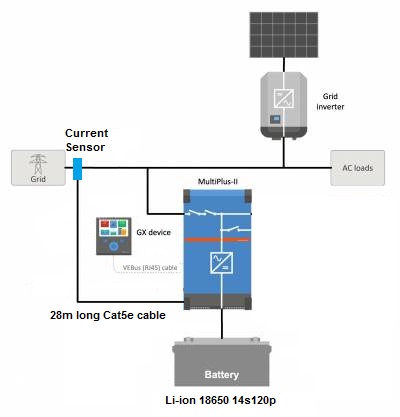
Previously I was using CT Sensor extended with Cat5e cable to over 25m long, the system looked like this:
The response to load was pretty much instant. I've recorder video using the same load as on the previous one (load switched on at about 10s and switched off at 23s of the video):
The system need seconds to stabilize
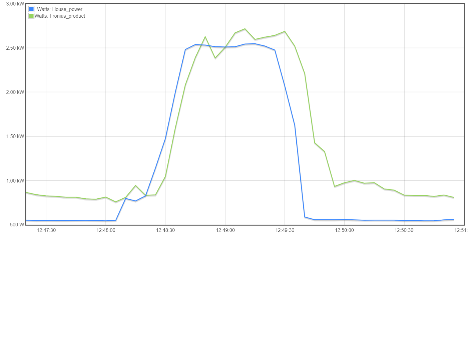
Also you can see a clear difference on the Grid use graph from VRM portal:
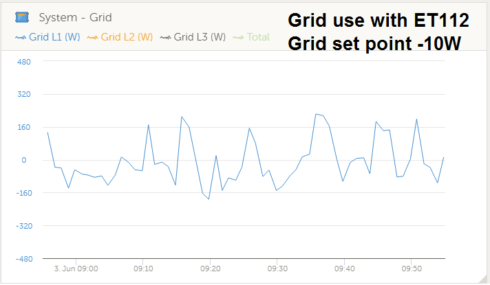
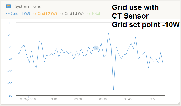
As you can see, with CT sensor the system is very close to grid set point, with ET112 grid meter it is way off and hardly ever stay close to set point. The situation is even worst during cloudy day when PV power is fluctuating (you cen see it on my other youtube video).
Is it normal behavior? It looks like Multi can handle this load easily, the problem seems to be in the feedback from the grid meter (or algorithm when ET112 is in use). Is there anything I can do to improve this reaction time??? Please advice.
Kind Regards
 hello,
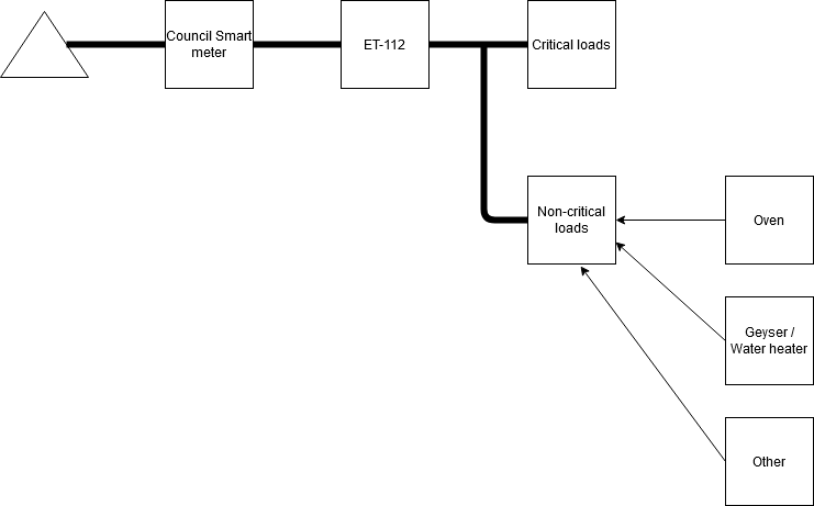
