I'd like to reopen discussion on this topic. I'm a novice and freely admit that I really don't understand all aspects of how to get this to work. So I may be totally off with this so please correct me if I'm wrong. I've read this thread:
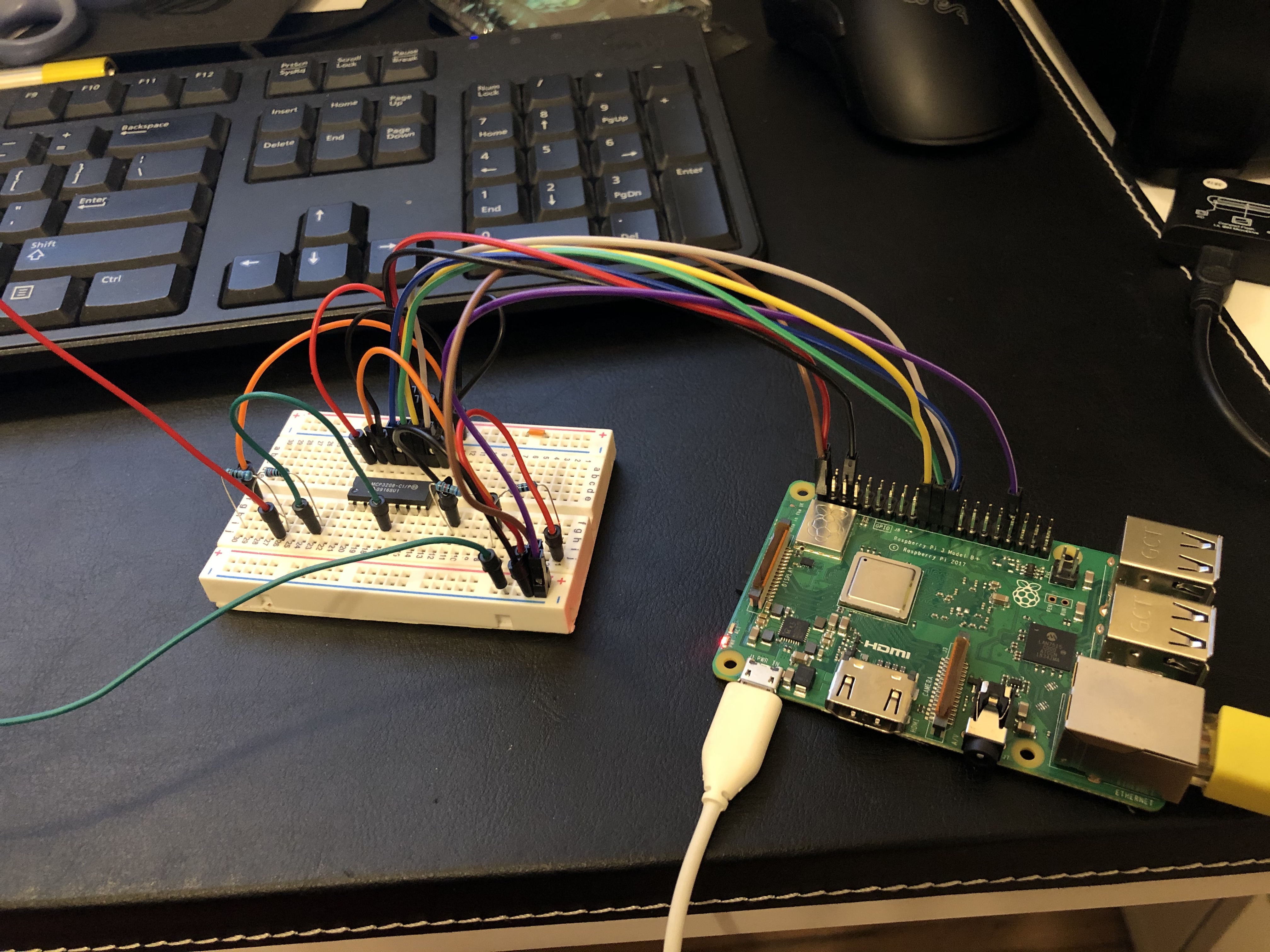
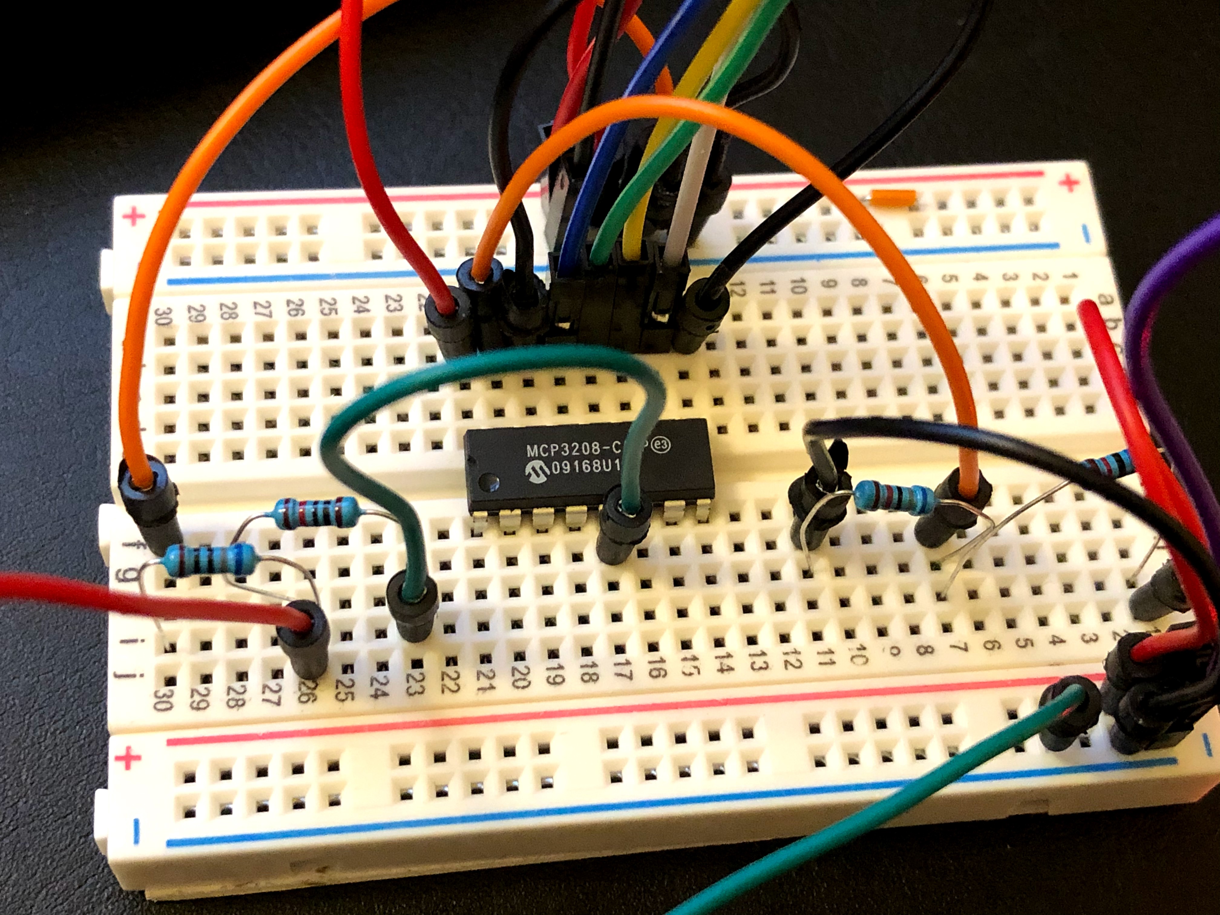
I purchased the same board as what's here, the Expander Pi with the mcp3208 12-bit ADC.
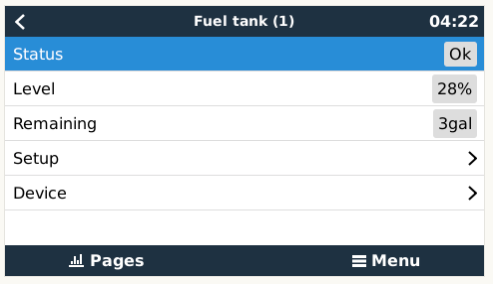
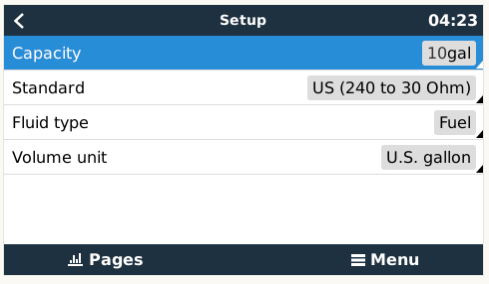
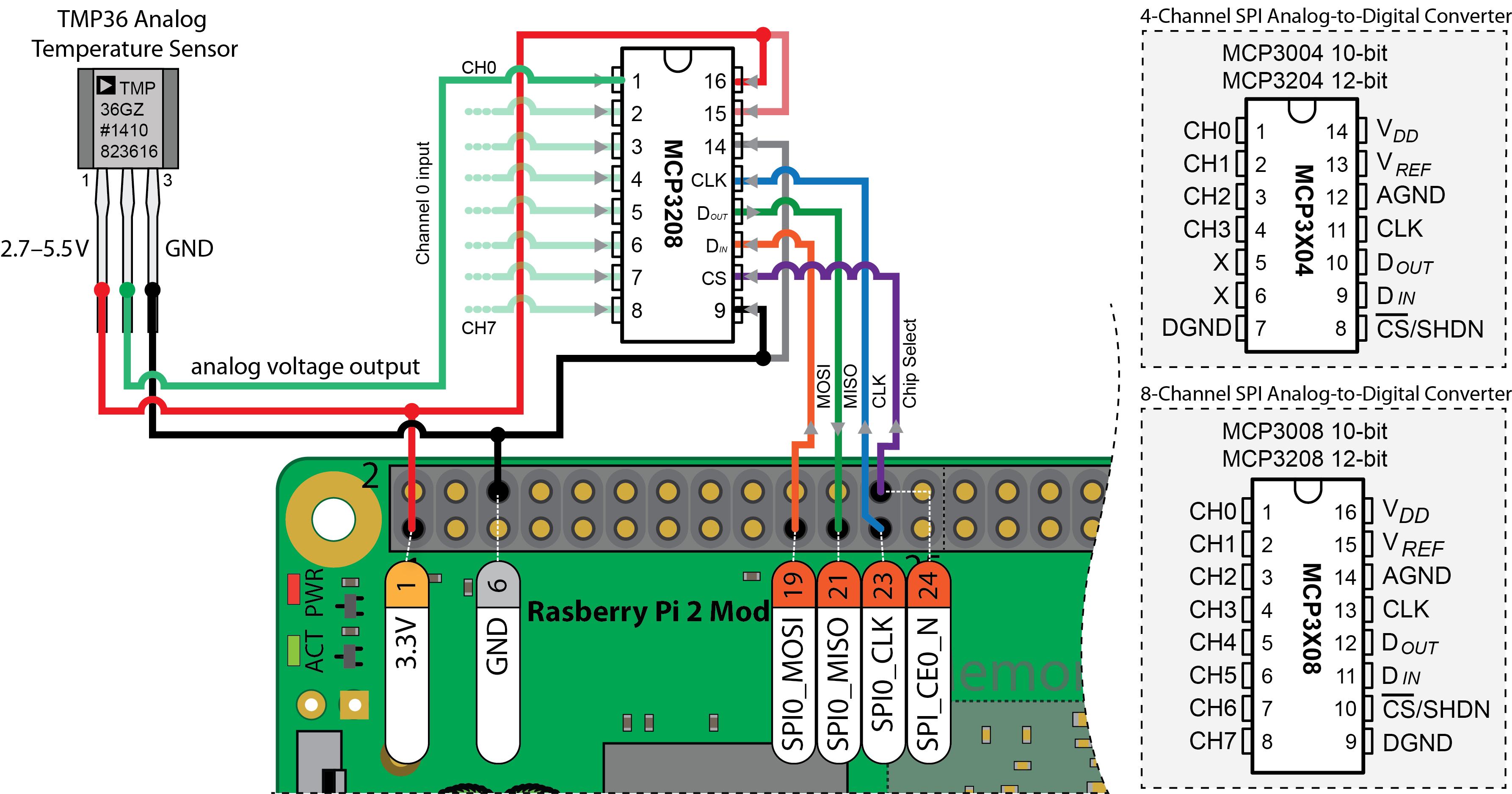
From reading this, I'm a bit confused how to wire this up. In that thread, they point to the reference voltage of 1.8v. However the expander pi has a reference voltage of 4.096. But in other threads, they talk about a reference voltage of 5v. I also see the schematic of the BBB Cape and it says 5v as well:
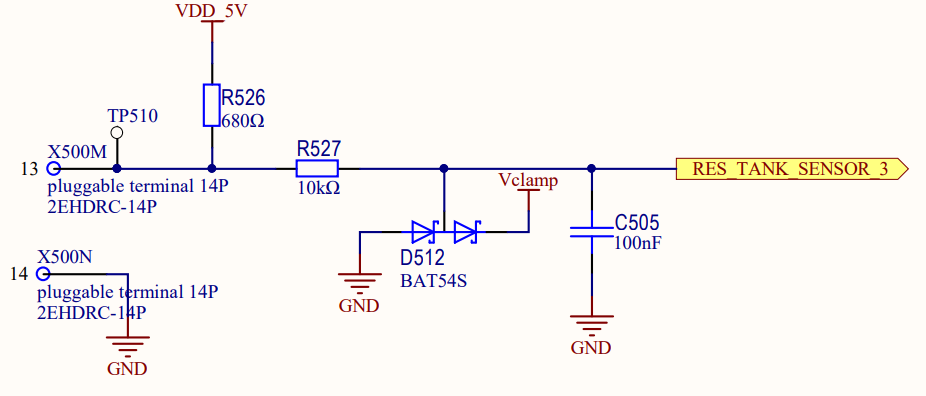
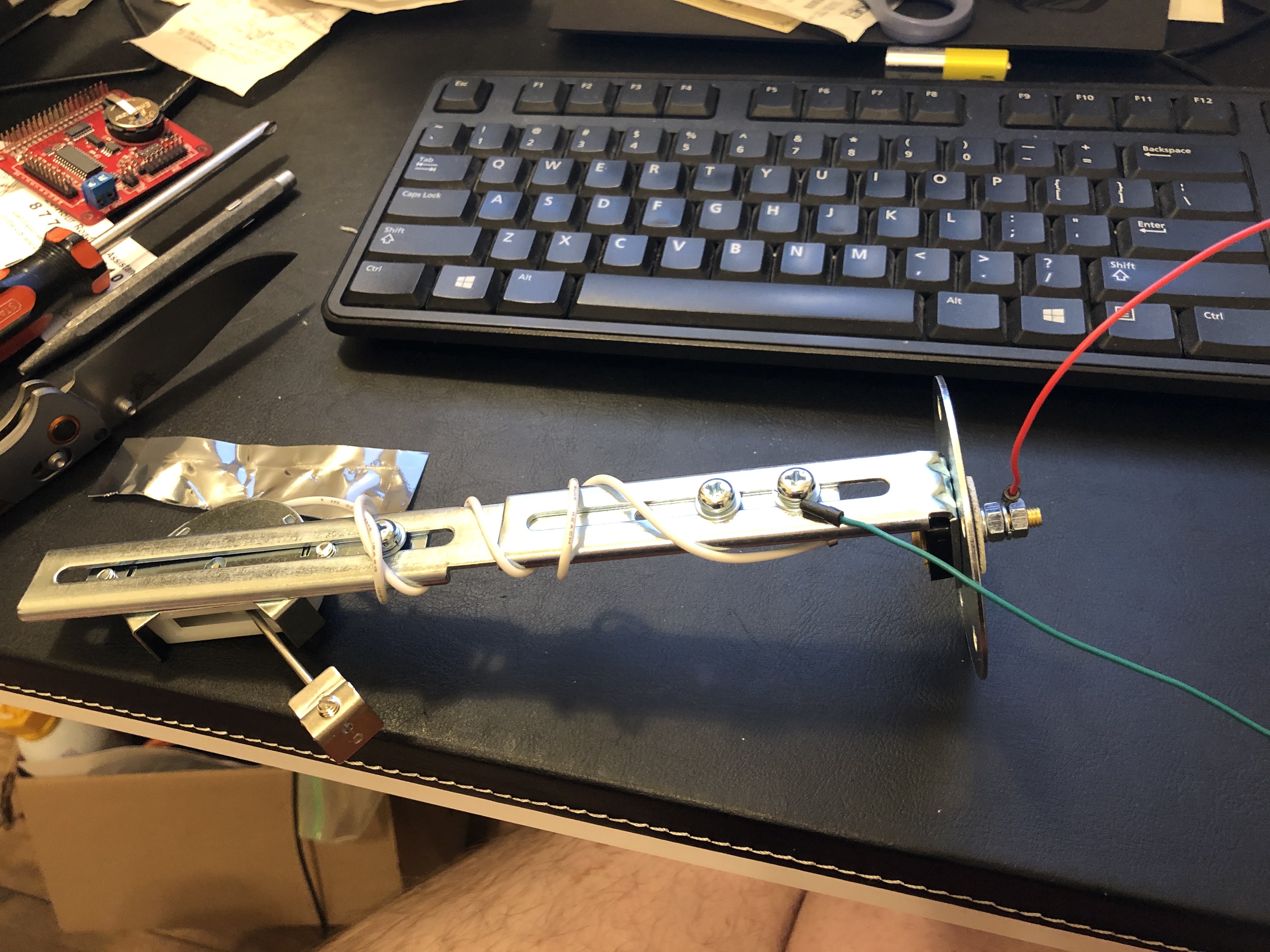
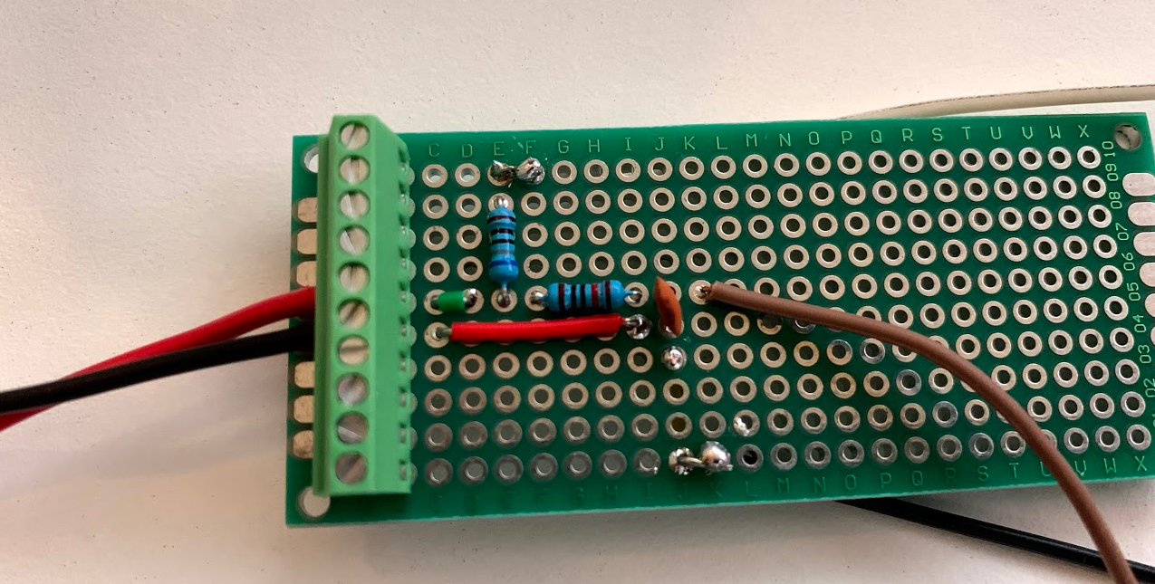
I'm not sure what is correct or if the reference voltage even matters since both are 12-bit ADCs, the reference voltage shouldn't matter as it's just reading the resistance of the sender. But then I'm confused on how to wire this up with the Expander Pi. Anyone who has this board, would they care to share their setup, possibly with photos or diagrams? I'd appreciate it.
tagging @WKirby as you've always been super helpful!

 What’s the Eta?
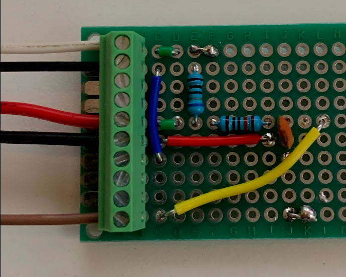
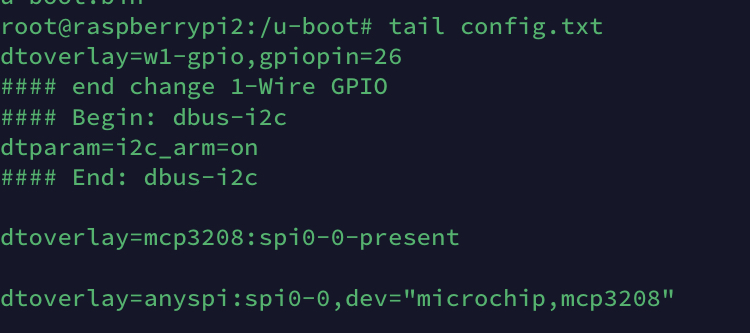
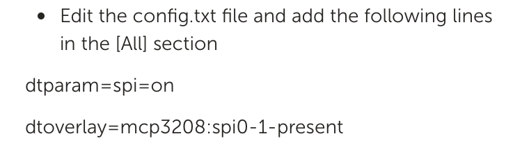
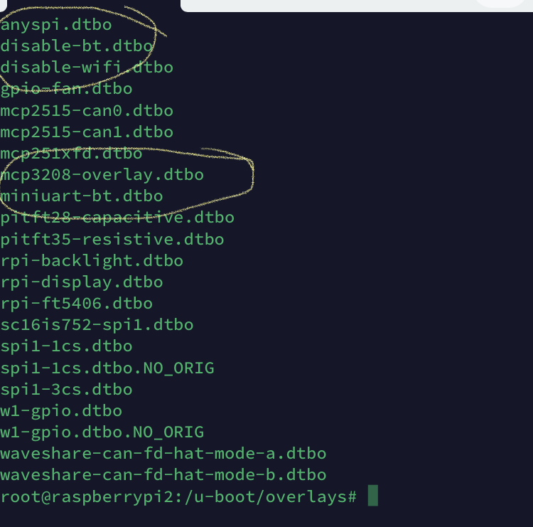 by correct overlay files do you mean these two?
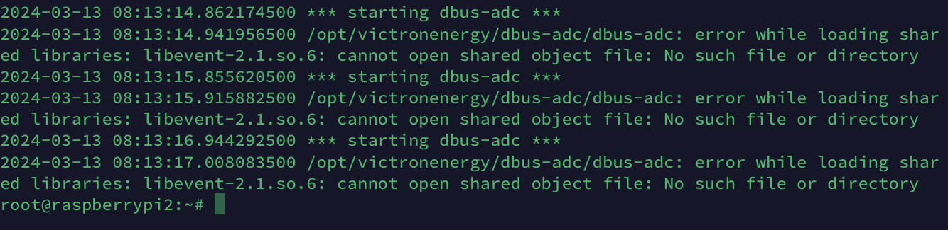
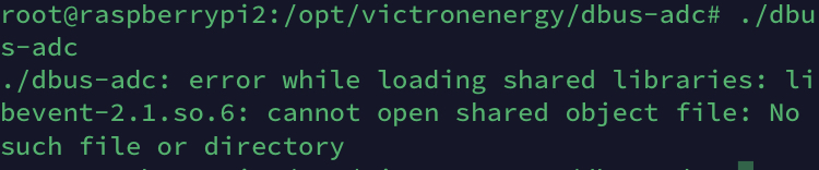
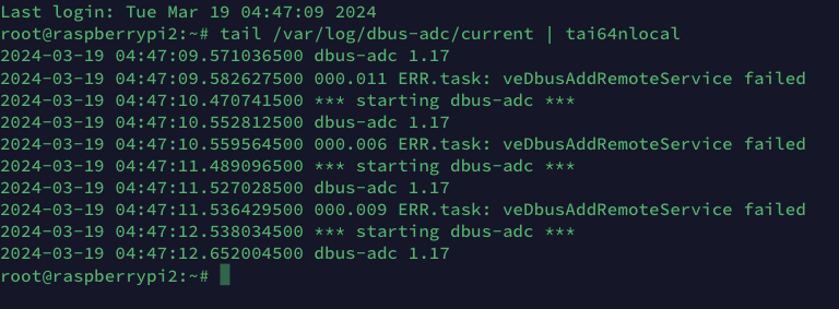 veDbusAddRemoteService failed