question

dunnp avatar image
dunnp asked

Tank sensor resistance values - some help please

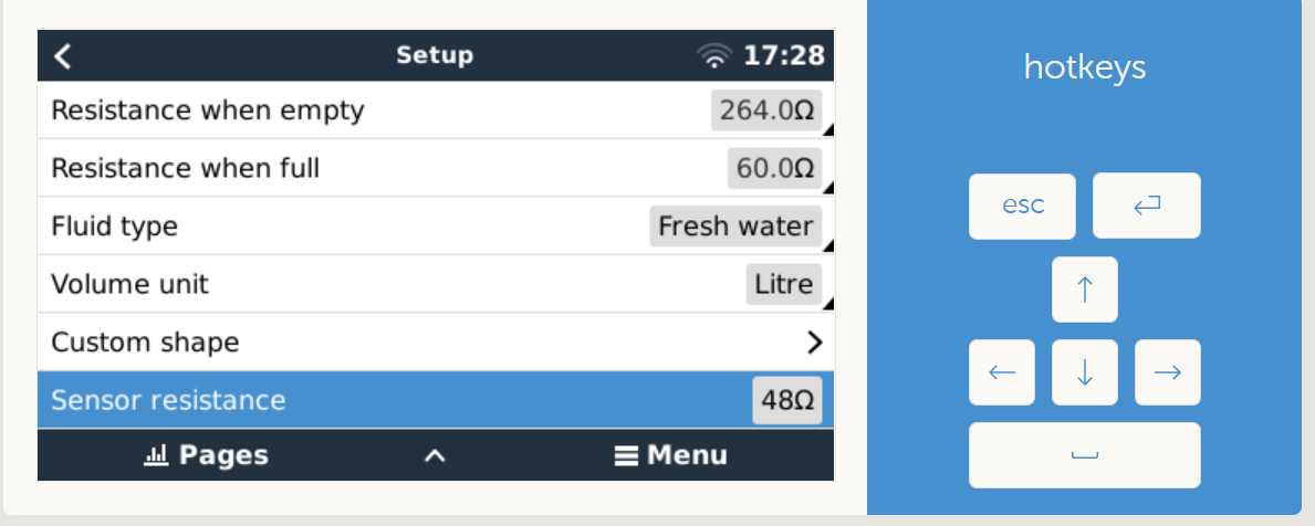
I'm trying to configure my tank sensors and am seeing some odd values in the raw 'Sensor resistance' field. If I put a short on the input, I get a reading of 48 ohms (ish). And all sensor readings are much higher than the actual circuit resistance. This causes problems when the tank sender reaches the 240 ohm end because the Venus reads something like 385 ohms and the upper limit in the custom setting is 264 ohms. (If this limit could be increased to say 400, this 'problem' would no longer be a problem).

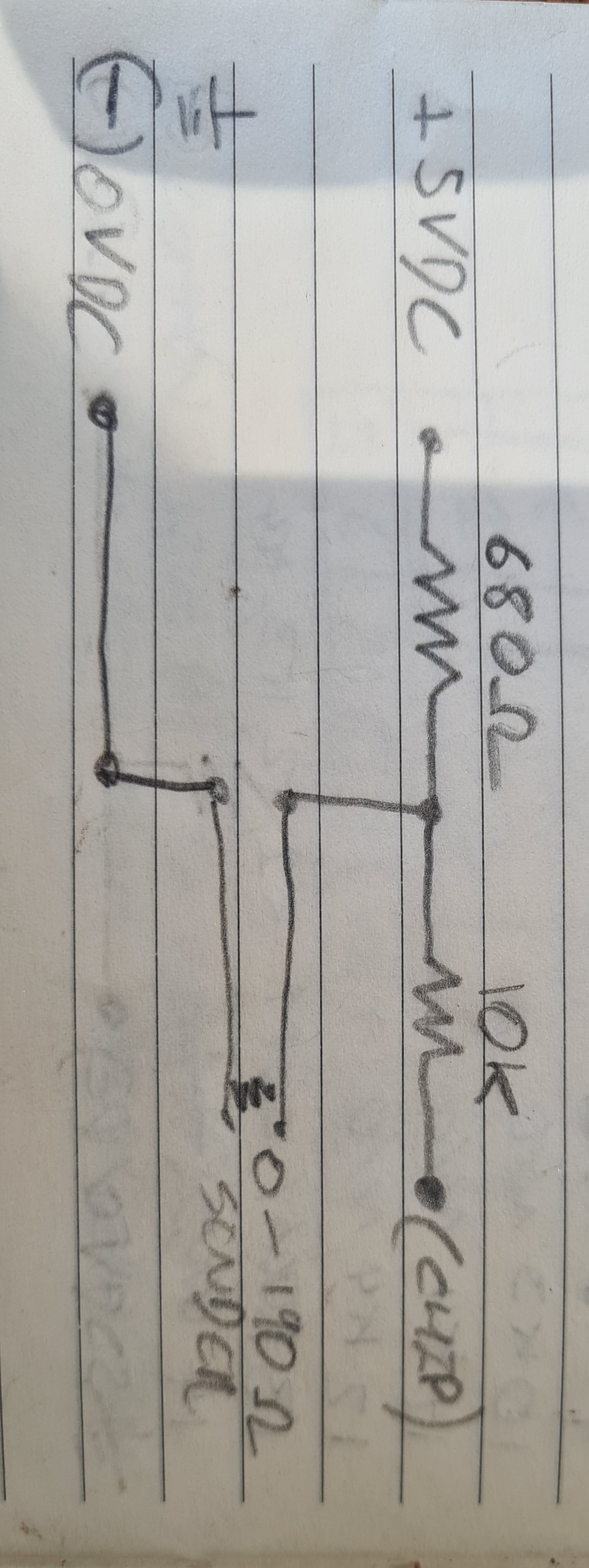
I'm using a RPi and made my own analog HAT with an MCP3208. I have checked and double-checked all the resistors match the factory Venus circuit and accurately set the VRef to 1.8V. VenusOS version is v2.60 and dbus-adc is v1.27.

What I am wondering - and asking - is for someone with a real Venus or Cerbo to put a short on a tank input and see what it reports as a 'Sensor resistance' in the Remote Console? If you see zero or close to zero, I will then know the problem is at my end. I just want to eliminate a Venus software bug as the cause before I tear any more hair out.

tank-resistance.png

Cheers

Phil

Venus OSRaspberry Pitank monitor
tank-resistance.png (70.1 KiB)
2 |3000

Up to 8 attachments (including images) can be used with a maximum of 190.8 MiB each and 286.6 MiB total.

4 Answers
Mark avatar image
Mark answered ·

Hi phil

I've made my own rpi and board too my tank sensors work OK. In the pic is how I made the sender circuit, hope this helps

20201115-101210.jpg


2 |3000

Up to 8 attachments (including images) can be used with a maximum of 190.8 MiB each and 286.6 MiB total.

dunnp avatar image
dunnp answered ·

Hi Mark.

Yes mine is the same circuit.

What do you see in the Remote Console screen per screenshot above if you put a short across the sender?

I see 48 ohms or so, not zero (ish).

Phil

1 comment
2 |3000

Up to 8 attachments (including images) can be used with a maximum of 190.8 MiB each and 286.6 MiB total.

Mark avatar image Mark commented ·

I never tried it but I will later and let you know what I see. I tested mine with a resister when I built it.

Cheers

0 Likes 0 ·
Rob Duthie avatar image
Rob Duthie answered ·

Hi

Attached circuit i have designed for the raspi which includes things required.

You have the modified MCP3208 overlay set to 10bit mode etc.

Victron Raspi Hat.pdf

Victron Raspi Stetson.pdf

Regards

Rob D

NZ


2 |3000

Up to 8 attachments (including images) can be used with a maximum of 190.8 MiB each and 286.6 MiB total.

dunnp avatar image
dunnp answered ·

Hi Rob

Yep - pretty sure my circuit matches yours. My 3208 is 12-bit - ie reads 0 to 4095. Is that not correct?

If you put a short on one of your tank inputs, what does the sensor resistance read on the remote console? (That was my original question).

Phil

1 comment
2 |3000

Up to 8 attachments (including images) can be used with a maximum of 190.8 MiB each and 286.6 MiB total.

Rob Duthie avatar image Rob Duthie commented ·

Correct 12 bit, there will be tiny differences in impedance, it will never be zero , Mine ver 2.60 has no sensor reading in resistance, you can calibrate by setting the full and empty values when you measure with a meter which will give you a very good full and empty in % readings. This is what is done and read OK

When you go into the raw data file reading i have never seen zero always varies because the data bit are only 10 to 12 bit.


Regards

Rob D

NZ

0 Likes 0 ·