Idea

laurenceh avatar image
laurenceh suggested

Home-brew Boxed HAT and CAPE - i2c and analogue inputs

Being a narrowboat owner I wanted to add some interfaces to Venus OS Rpi Project to:

  1. take more temperature readings
  2. provide tank level interfaces
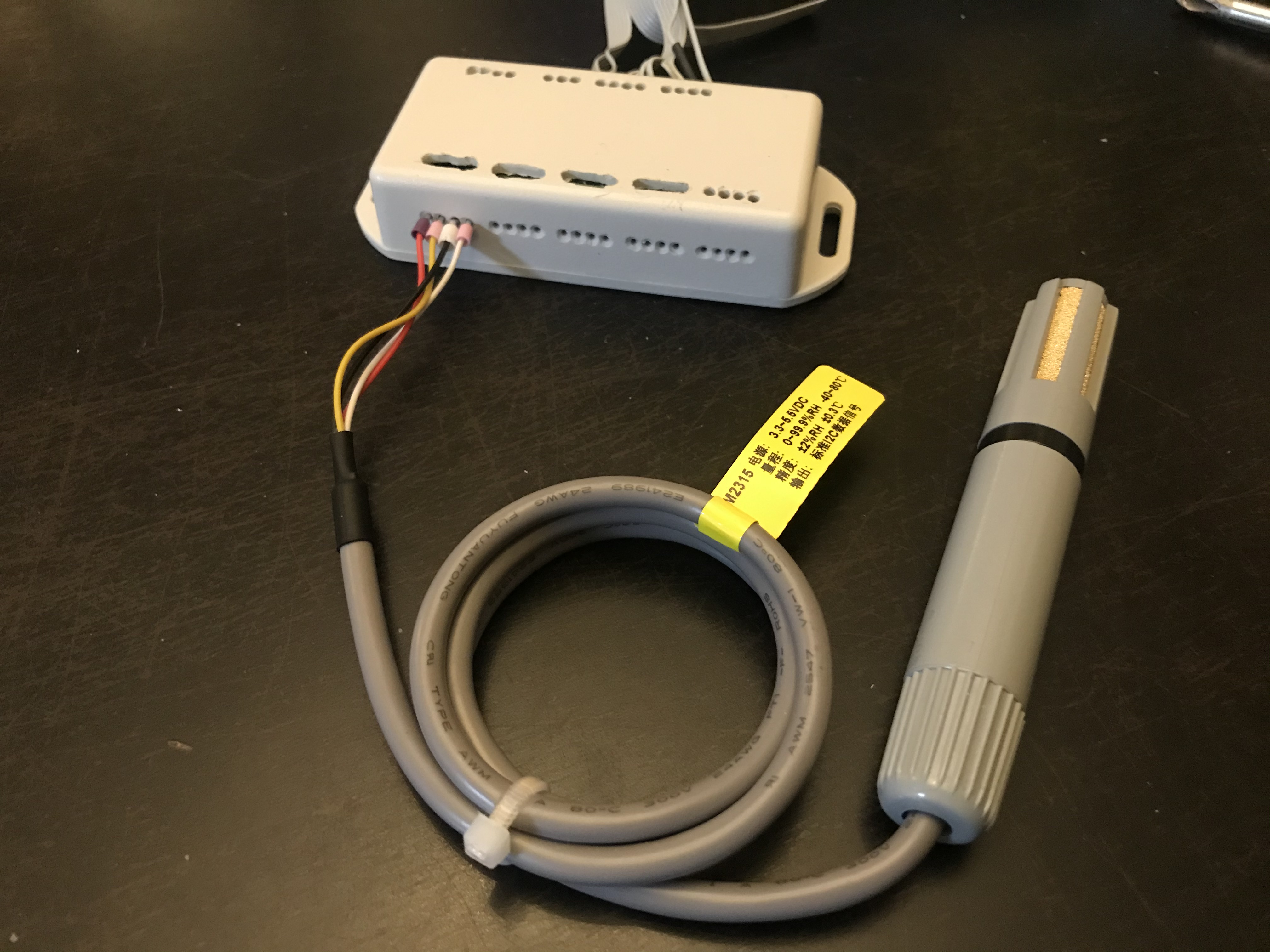
  3. read temperature and humidity using a rugged sensor (illustrated below)
  4. Keep the size down as space is always limited on a boat.

The following has been tested on Rpi 3B+ and Venus OS 2.42 in Feb 2020

This post details the hardware I have constructed (software configuration to be posted elsewhere)

1)

Take a RaspberryPi, Touch Screen, Smart Touch 2 case, + 15 mm back box

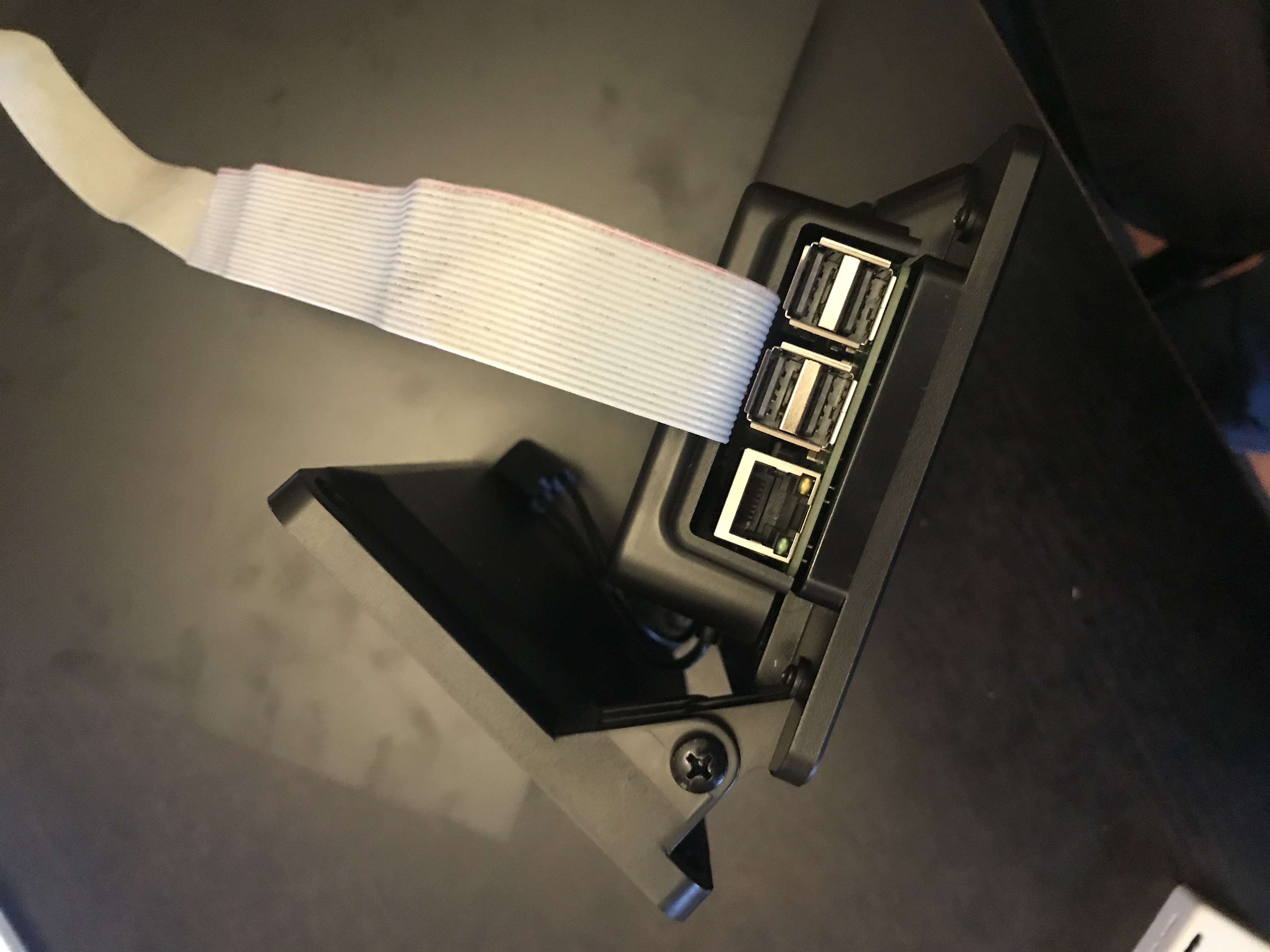
Fit a custard pi 3A HAT and a ribbon cable header as shown here:

NB the Custard Pi 3A uses the mcp3208 analogue interface board, other boards are available which use this interface chip and could probably be used. The Custard pi 3A is fitted with a 2.5v reference shunt. Research has indicated that the 3.3v on the Rpi is known to be stable and well regulated, therefore the 2.5v shunt was removed and a 1.2k resistor fitted instead. This resistors then forms a voltage divider with the 1k resistor already fitted on the HAT producing 3.3*1.2/2.2 = 1.8 v which should be as stable as any other 1.8v reference method.

The ribbon cable picks up 3.3v / 5v / GND and the i2c Data and Clock signals from the GPIO header which is piggy backed on the Custard pi board. 8 wires of the ribbon cable (not connected to the GPIO header) are connected to the analogue inputs.

This all fits inside the screen mount and back box like this:

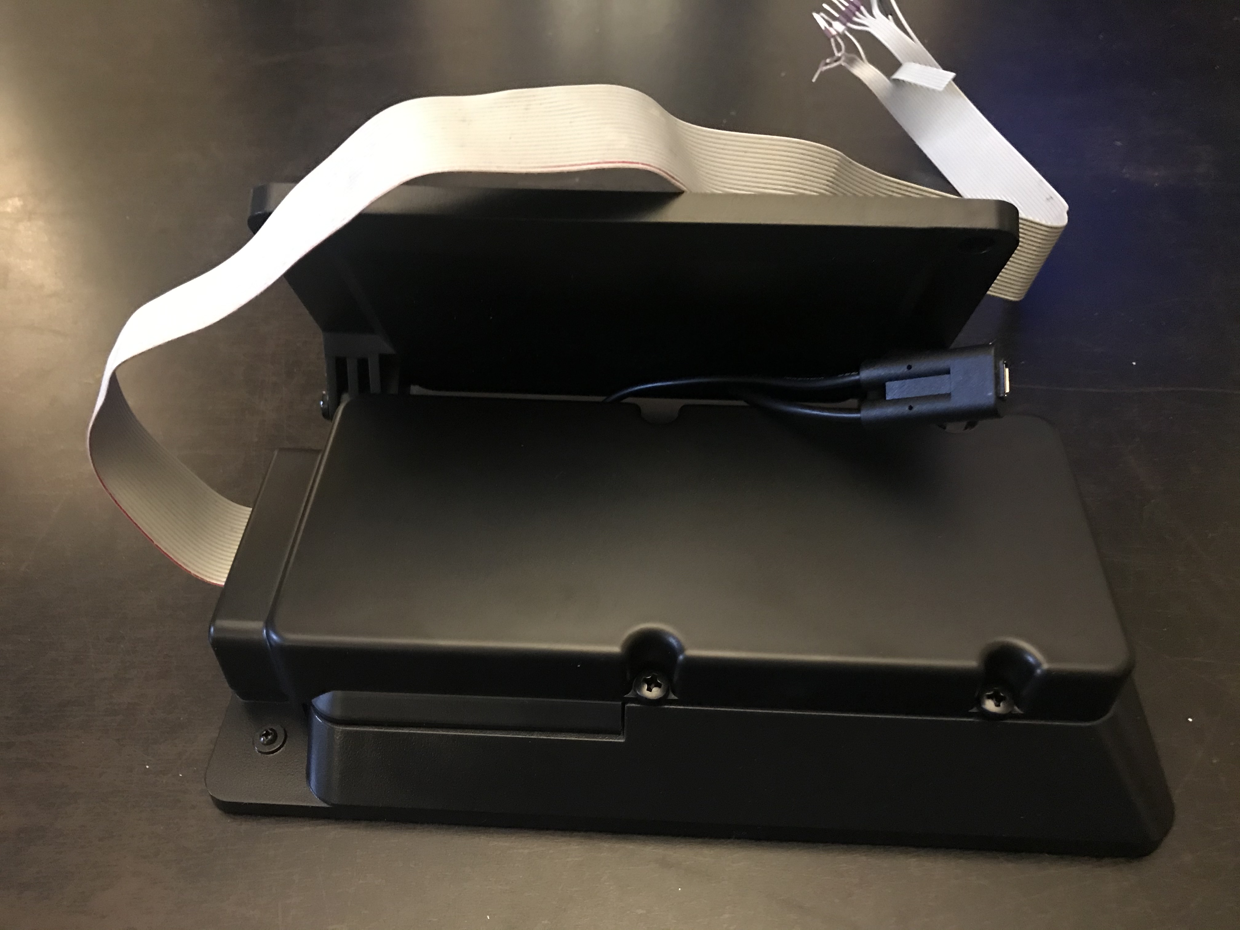
NB for long term use I will put a little protection round the ribbon cable.

The display will be hinged from the roof of the electrics cupboard so out of the way until lowered to view the display.

2) I constructed the CAPE circuit in a box about 8x4x2 cm it looks like this:

The device connected is an i2c device the 16 holes for connecting the 8 analogue inputs can be seen. The holes in the top provide access to the screws on the terminal strips. Once installed a sticker will be placed over the screw access holes to protect the box from dirt and dust. The holes in the side are a tight fit for bootlace ferules used to terminate the cables. (I will temporarily connect a temperature sensor inside the box on one of the analogue inputs to check for temperature rises inside)

Inside the box the circuit is constructed to replicate the published CAPE circuit like this:

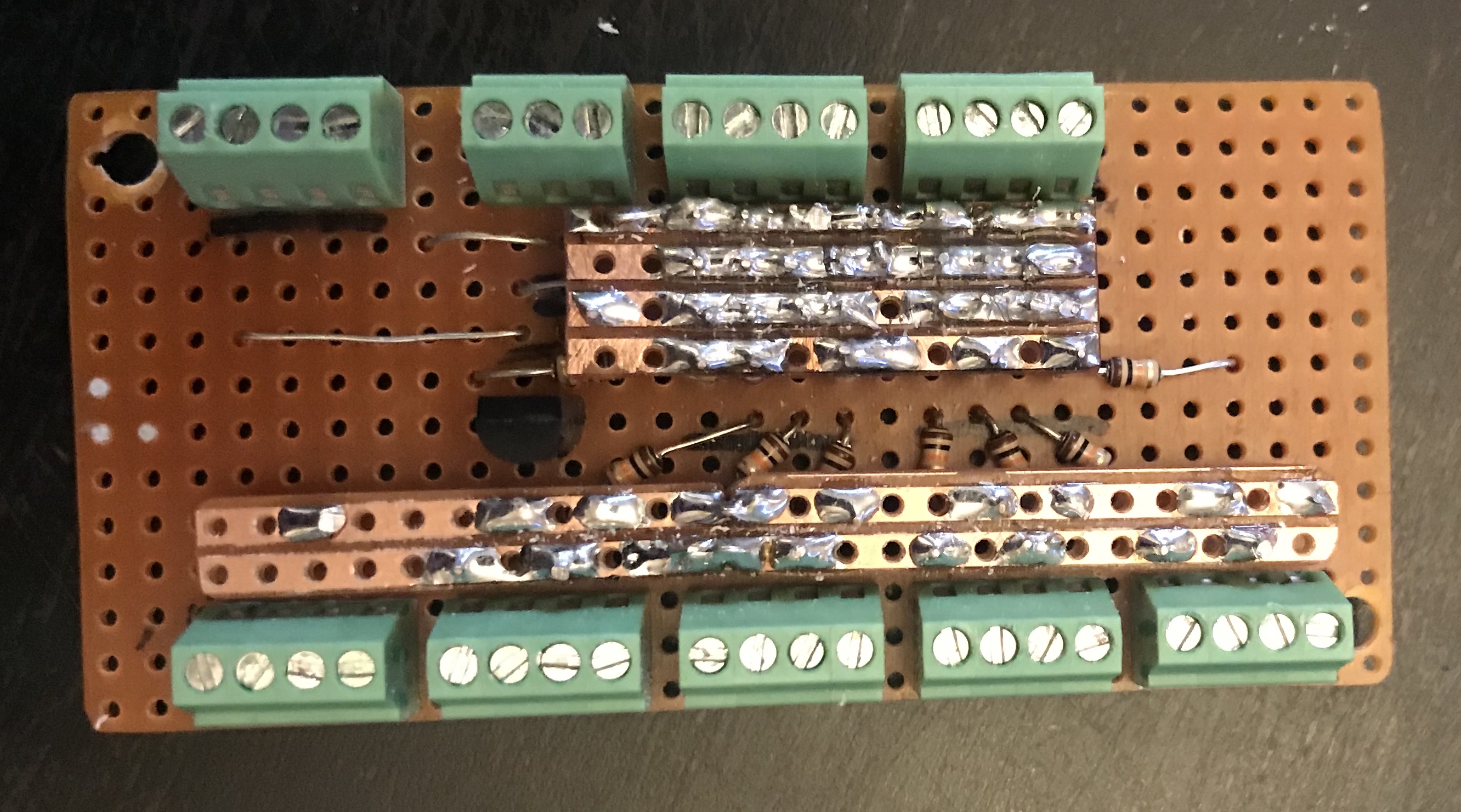
The construction is based on a matrix with each of the 8 inputs running vertically in this picture, on the underside of bottom board, and horizontal busses mounted above the components for GND, vClamp and 5v.

Most of the components are sandwiched in between two boards, mounted vertically like this:

You can see the following which are mounted vertically:

  • Capacitors to a GND bus bar
  • Schottky diodes to a GND bus bar
  • Schottky diodes to a vClamp bus bar
  • Pull down resistors to a GND bus bar

The series 10k resistors can be seen mounted across the board. The vClamp regulator can also be seen.

The pull up resistor on the inputs are fitted in a similar manner but are not shown in this image.

The i2c connections are fed directly across between the input and output side of the box.

This has all been tested and appears to be working ok.

Next steps

This provides a stable and robust platform to use for software development and testing before installation.

I am aware of the project to produce a commercial Venus OS Rpi HAT by @Rob Duthie and for many that will be the way to go but for me I wanted to get to grips with how everything works by constructing this.

Venus OSVenus GX - VGXRaspberry Pi
img-8982.jpeg (2.1 MiB)
img-8981.jpeg (1.5 MiB)
img-8980.jpeg (1.7 MiB)
img-8991.jpeg (1.0 MiB)
img-8985.jpeg (1.8 MiB)
img-8977.jpeg (1.0 MiB)
img-8969.jpeg (1.3 MiB)
2 |3000

Up to 8 attachments (including images) can be used with a maximum of 190.8 MiB each and 286.6 MiB total.

jeroend avatar image
jeroend commented

Nice work!

2 |3000

Up to 8 attachments (including images) can be used with a maximum of 190.8 MiB each and 286.6 MiB total.

Duncan Hall avatar image
Duncan Hall commented

I have followed the above recipe using the custard Pi 3b and replacing the 2.5 shunt with a 1.2k resistor and get a v ref of 1.814V.


I have tried seting up 4 temperature sensors. The inpit voltages to the ADC are all arround 0.96v as expected.


However, when I log onto the remote console I don't see any analogue inputs.


I am using a Raspbery Pi 3B with V2.66.


Am I missing something?

10 comments
2 |3000

Up to 8 attachments (including images) can be used with a maximum of 190.8 MiB each and 286.6 MiB total.

laurenceh avatar image laurenceh commented ·

Duncan

Check my post here https://community.victronenergy.com/questions/61933/whats-happening-with-venus-260-what-did-my-system.html

Particularly the dbus-adc package and the dbus-adc.conf file.

I’m away from my workbench right now if your still having problems I can check it out next week with 2.66.

0 Likes 0 ·
Duncan Hall avatar image Duncan Hall laurenceh commented ·

As a simpler fix I downloaded 2.42 and find it the same. i.e. no analogue inputs.

0 Likes 0 ·
laurenceh avatar image laurenceh Duncan Hall commented ·

Duncan

What is not clear from you posts is what software steps you have taken (if any) to get things configured. Do you have dbus-adc service installed is it running (ps -ef | grep dbus-adc)?

What are the contents of YOUR dbus-adc.configured file?

Have a look in /var/log/dbus-adc for any log messages that may give a clue.

What is clear is that installing the hardware will not work without you making some software / configuration changes as well. What is not clear currently is what have you actually done other than install the hardware?

I can point you at articles with the software configuration instructions or scripts if you need more information.

0 Likes 0 ·
Duncan Hall avatar image Duncan Hall laurenceh commented ·

Thanks


I have been doing more checking. I was not initially aware of software changes needed.


I can confirm that the ADC works as I loaded the standard raspberry pi OS and ran sf innovations testing software which correctly read the voltages once allowance is made for changing vref.

0 Likes 0 ·
Duncan Hall avatar image Duncan Hall Duncan Hall commented ·

A little further I followed the posts in

https://community.victronenergy.com/questions/61933/whats-happening-with-venus-260-what-did-my-system.html

when I type

opkg update

opkg install dbus-adc

I get error messages indicating several packages failed to download

the second command says no packages installed or removed

I am using V2.7-~17

0 Likes 0 ·
laurenceh avatar image laurenceh Duncan Hall commented ·

Duncan

That is useful I can try this and see what is happening. I’ll be back at my workbench on Tuesday so can give it a try. Unless anyone else can answer this for 2.7 ?

I might however suggest that if you are going to use it that you go back to a stable release, the ~ releases are intended more for testing than for actual use.

0 Likes 0 ·
Duncan Hall avatar image Duncan Hall laurenceh commented ·

I used that in anticipation of its intended release and the fact that I need to burn a new SD card for 2.70. Still on a learning curve as Its about 10 years since I have used unix. I did lots then but it comes back slowly.


I recall having the same error messages in 2.66


I am probably missing a full description of the software changes needed to enable it.

0 Likes 0 ·
laurenceh avatar image laurenceh Duncan Hall commented ·

Duncan

As Rob has confirmed don’t try to use 2.7 yet.

The details you need are in the article here.

https://community.victronenergy.com/articles/43646/how-to-quickly-update-rpi-touch-screen-configurati.html?childToView=48991#comment-48991

You can read the script to see the required steps to enable the analogue interface which include having the overlay file for the mcp3208 and the dbus-adc service as already described. You should be able to download the zip file and follow the instructions. You will however need the newer version of dbus-adc and to create the configuration file as the script was written before these changes and I have not updated the zip package.

There are other links in the article ( and contribution from Rob and others) you should follow and read to understand more about what is needed.

Laurence


0 Likes 0 ·
Rob Duthie avatar image Rob Duthie laurenceh commented ·

Hi

Note: if using ver2.70 your analog will not function anymore plus other function don't work, Stick to Ver 2.66. all works OK.

As the rocko to zeus update has caused issues. The releases are for public stable systems only. The candidate, testing and developer are for testing only.

0 Likes 0 ·
roosmsg avatar image roosmsg Rob Duthie commented ·
Will this work with v2.85?
0 Likes 0 ·
Duncan Hall avatar image
Duncan Hall commented

My version 2.66 works OK

If I conp my scripts over to a system on 2.85 it will not allowme to make changesto thefilesystem which has been made read only.


Has anyone got a way to fix this. My system works 2.66 but I preferr to not stay stuck with a legacy version

1 comment
2 |3000

Up to 8 attachments (including images) can be used with a maximum of 190.8 MiB each and 286.6 MiB total.

laurenceh avatar image laurenceh commented ·

@Duncan Hall I have have accepted commits from contributors to the Dbus-i2c service in the article here.

https://community.victronenergy.com/questions/58792/raspberry-pi-3b-heat-temperature.html

According to the contributors and what I understand these changes solve the problems with working on Venus OS 2.8 and above using my code. It may help you with your problem or you might be using my service code anyway.

Laurence

0 Likes 0 ·

Your Opinion Counts

Share your great idea, or help out by voting for other people's ideas.