question

bathnm avatar image
bathnm asked

Exploring VenusOS / VE.Bus BMS / MQTT or Modbus TCP limitation logic

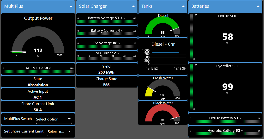
I have a Cerbo, Smart Lithium batteries, MultiPlus, VE.Bus BMS, Solar controllers, etc. So an all Victron setup.

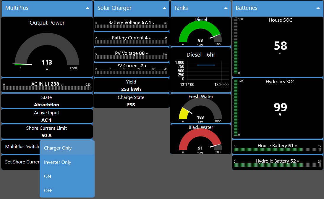
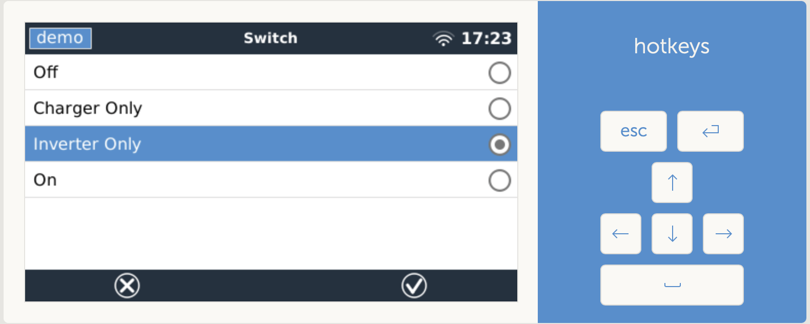
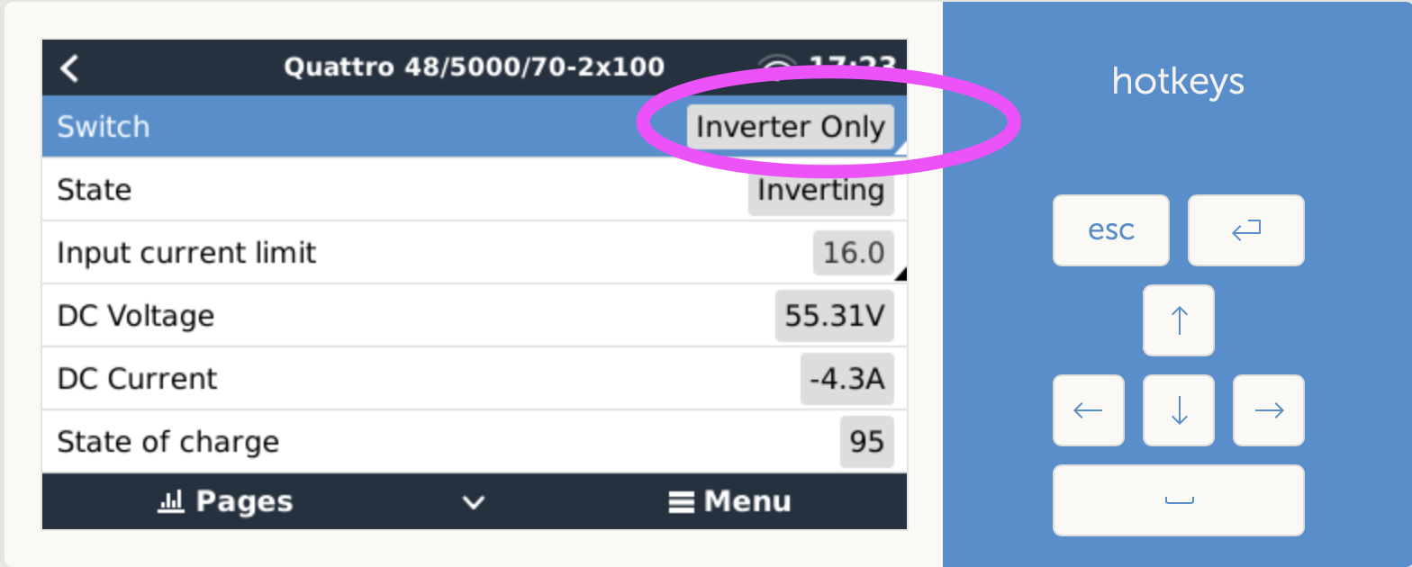
I have been struggling with the limited ability to control the MultiPlus from within the Cerbo. I understand the suggested approach is to deploy a DMC. However, this does not allow any form of real remote control, just a manual switch on panel.

From searching the web it seems that the constraint is there to stop the system getting confused, or the user doing something which is not sensible. So why does it work with a 2-Wire Assistant, but not VE.Bus BMS assistant, so I started to test and explore the system.

From all my testing I can understand why when a DMC is in the system that the capability is blocked, however when there is just the VenusOS and VE.Bus BMS it is not clear. When no DMC exists, the VenusOS is the only device that could control the MultiPlus and it also knows the charge and load disconnect status so can ensure nothing untoward happens.

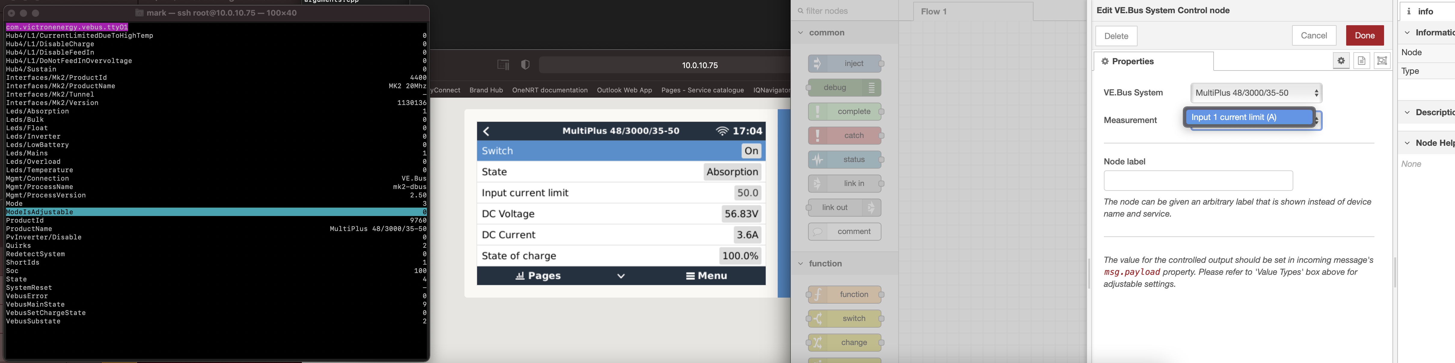
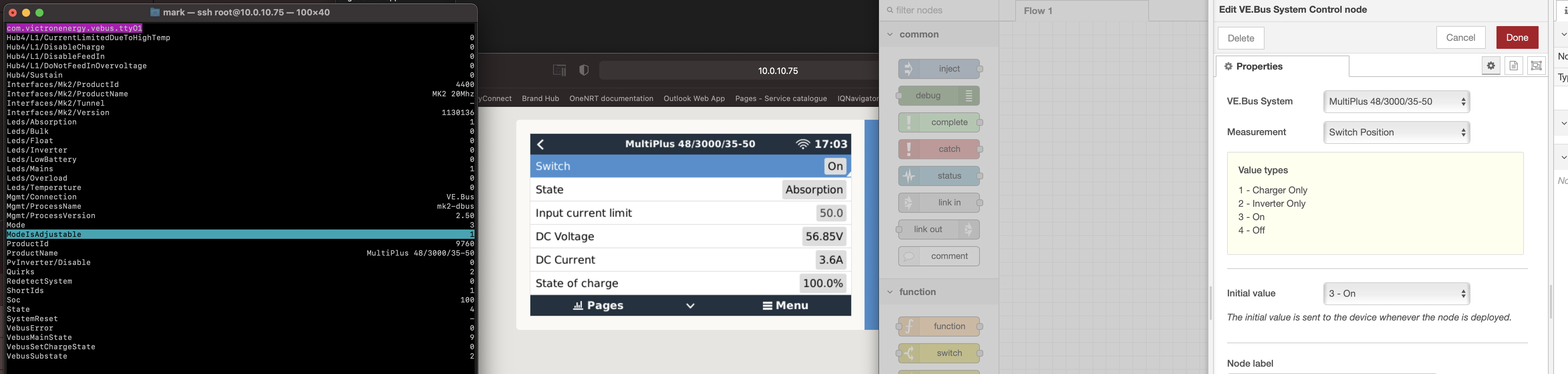
From testing it would seem a simple logic change to one D-Bus data element controlled by the mk2-dbus service would allow controlling the MultiPlus mode/switch from within VenusOS.

Is there anyway Victron might consider a change to the logic within the mk2-dbus service so that when no DMC is deployed the remote control of the MultiPlus can be enabled and thus scripts, MQTT or Modbus TCP can eventually be used to control the MultiPlus. This would be of great benefit to a large number of people and really good addition to the Victron eco system

Many Thanks

P.S If you want my testing detail and output I am happy to share.

MultiPlus Quattro Inverter ChargerVenus OSBMSVE.BusDigital Multi Control
2 |3000

Up to 8 attachments (including images) can be used with a maximum of 190.8 MiB each and 286.6 MiB total.

5 Answers
Peter Buijs - NL avatar image
Peter Buijs - NL answered Ā·

I am not sure but I think there are possibilities in the Large version of VenusOS which has Node-RED included.

This is a Node_RED Dashboard in VenusOS Raspi displaying the Boat/Motorhome Demo

1604578748470.png

1604578793539.png


1604578748470.png (73.8 KiB)
1604578793539.png (76.9 KiB)
1 comment
2 |3000

Up to 8 attachments (including images) can be used with a maximum of 190.8 MiB each and 286.6 MiB total.

bathnm avatar image bathnm commented Ā·

@Peter Buijs - NL, thank you. The Boat demo on my test RaspberryPI also allows me to change it, see below.

1604597009698.png1604597031721.png


The reason for this is that the D-Bus data element ModeIsAdjustable is set to 1. However on my yacht when the VE.Bus BMS is physically connected to the VE.Bus it is set to 0 and the screen is no longer available.

Looking at ModBusTCP material it is stated the mode switch is not available when a VE.Bus BMS is in place. I suspect that MQTT will have the same constraint.

If you are familiar with the install on Raspberry PI you can get on teh command line and use the command dbus-spy to edit this data element under 'com.victronenergy.vebus.ttyO1' and set it to 0. I suspect under Node-Red the capability will disappear.

If you ant, then I'll install Node-Red later this week and confirm myself.

Once again, many thanks.

0 Likes 0 Ā·
1604597009698.png (126.6 KiB)
1604597031721.png (86.8 KiB)
Peter Buijs - NL avatar image
Peter Buijs - NL answered Ā·

When com.victronenergy.vebus.ttyO1 ModeIsAdjustable = 0 it is possible to change the com.victronenergy.vebus.ttyO1 with the Node-RED Dashboard UI

When I change the Mode in the Node-RED Dashboard UI the com.victronenergy.vebus.ttyO1 Mode value reflects the change in dbus-spy


1 comment
2 |3000

Up to 8 attachments (including images) can be used with a maximum of 190.8 MiB each and 286.6 MiB total.

bathnm avatar image bathnm commented Ā·

Interesting. I am using teh demo and not production, so do not have a MultiPlus physically connected. I have found actually that with a MultiPlus physically connected the ModeIsAdjustable can't actually be changed by dubs-spy. Anyway with node-red I see this.

set to 1

1604682202726.png


set to 0

1604682258470.png


Have not been able to setup a dashboard yet.

0 Likes 0 Ā·
1604682202726.png (1.1 MiB)
1604682258470.png (1.2 MiB)
Rene Mullie avatar image
Rene Mullie answered Ā·

I tried this as well, I have Multi and VEbusBMS, over mqtt the state of Multi or shorepower limit can NOT be changed. Only with connected DMC. I have been looking for solution for months now, not sure why this is impossible....maybe Matthijs can give some insights on this issue? I see many requests for this as rhis is crucial for remote controll in this combination/setup.


2 |3000

Up to 8 attachments (including images) can be used with a maximum of 190.8 MiB each and 286.6 MiB total.

mvader (Victron Energy) avatar image
mvader (Victron Energy) answered Ā·

The answer is that the VE.Bus BMS uses the same or similar controls as Venus OS does, when changing the mode (on/off/charger-only) of the inverter/charger.

And to fix this the design of the VE.Bus BMS needs to be updated; which is what we're doing. ETA quite some many months from now. Minimum 6, but can also be 12.

This limitation is documented in the manual here: https://www.victronenergy.com/media/pg/Cerbo_GX/en/installation.html#UUID-76254a30-8792-196a-b745-f25cae216b7f.

And I'm (more!) than aware how frustrating this limitation can be.

Besides waiting for a new version VE.Bus BMS, the other options is our soon to be launched Lynx Smart BMS; first sales to happen next month I expect.


1 comment
2 |3000

Up to 8 attachments (including images) can be used with a maximum of 190.8 MiB each and 286.6 MiB total.

simon-2 avatar image simon-2 commented Ā·

Is it still being worked on? It is now soon the 12 months around. It would be very nice to get the update for the VE.Bus BMS or another solution for the problem.


At least to know if the plan for an update still exists or if it has been thrown out would be helpful.


I still have hope.

0 Likes 0 Ā·
Thomas Sowa avatar image
Thomas Sowa answered Ā·

Hey,

i have the same problem in a newly installed System. Cerbo GX / VE.Bus BMS V2 / Quattro 24/5000

Is there still no solution?


4 comments
2 |3000

Up to 8 attachments (including images) can be used with a maximum of 190.8 MiB each and 286.6 MiB total.

mvader (Victron Energy) avatar image mvader (Victron Energy) ā™¦ā™¦ commented Ā·
What problem are you having?


The VE.Bus BMS v2 is the ā€œsoon comingā€ product referred to in above answers from year 2021.

0 Likes 0 Ā·
Thomas Sowa avatar image Thomas Sowa mvader (Victron Energy) ā™¦ā™¦ commented Ā·

Thank you very much for your answer.

So it should work? But why is ModeIsAdjustable 0 and can I change it somehow?

0 Likes 0 Ā·
simon-2 avatar image simon-2 mvader (Victron Energy) ā™¦ā™¦ commented Ā·

@mvader (Victron Energy) can you confirm that the ve.bus bms v2 solves the remote control of the multiplus2 with a cerbo (modbus and/or mqtt)?


If so, I would change my bms to the new version.

My goal is to control all my devices in my van over home assistant. So I need an interface like modbus or mqtt.


Thank you very much!


PS: In the manuals of the bms v2 I saw that the cerbo is now connected to the remote port of the bms. Is it any different than have the cerbo connected through the multiplus2?

And what would happen if I plug the cerbo intro the remote port of the bms v1?


0 Likes 0 Ā·
mvader (Victron Energy) avatar image mvader (Victron Energy) ā™¦ā™¦ simon-2 commented Ā·

Hi @simon_ , yes, VE.Bus BMS v2 does not disable the on/off controlling of a Multi.


While having the older VE.Bus BMS in a system does.

Details here:

https://www.victronenergy.com/media/pg/VE.Bus_BMS_V2/en/appendix.html#UUID-2dd07e2d-a21c-abbb-56b3-e20bb3b7fe24


Wrt what would happen if you connect the BMS v2 in a different way than prescribed in the manual: I donā€™t know. Please just donā€™t do that.


Success!

0 Likes 0 Ā·