Hello Everyone.
Could I please have your advice on configuring and switching on a newly installed DVCC system in a yacht? Questions at the bottom. First, a system description. The devices involved are:
- three 12.8V Smart lithium batteries, in parallel as the house battery bank
- Smart BMS CL 12-100, to keep the diesel engine’s alternator safe from overheating
- Smart Battery Protect 220 for load disconnect
- Smart Battery Protect 100 for charge disconnect of MPPT output (might change to a 220)
- Smart Shunt
- Cerbo GX and GX Touch 50 display
- MultiPlus 12/3000/120 - 50
- three 100/50 MPPTs with three x 400W solar panels
There are also two battery chargers connected to the positive bus-bar, being:
- an Orion-Tr 12/12-30 battery to battery charger, for charging the engine start battery, if needed
- a Sterling 12-24 charger for charging the 24V battery bank for the bowthruster
Data connections between the devices are:
- VE.Direct cable between the Smart Shunt and the Cerbo GX
- VE.Bus between the MultiPlus and the Cerbo GX
- VE.Direct-to-USB between the MPPTs and the Cerbo GX
And of course there are:
- load disconnect cable from the Smart BMS CL 12-100 to the Smart Battery Protect 220
- charge disconnect cable from the Smart BMS CL 12-100 to the Smart Battery Protect 100
I’ve read the DVCC information in the Color Control GX Manual. I’d happily read more information if it was available. :-)
How do the following configuration steps look to you?
- I need to activate DVCC in the Cerbo GX. Easy.
- I’m thinking I will activate ‘Limit charge current’ at first, to keep charging calm, at 50 amps max
- Shared Voltage Sense (SVS) comes on by default when DVCC is enabled. From Section 4.4.2 of the Manual, I gather the Smart Shunt will be the source of the voltage measurement, rather than the MultiPlus. This makes sense, so I think I’ll leave SVS on.
- Shared Temperature Sense is a problem. The system doesn’t have a temperature input at present. The batteries in the bilge are likely to be colder than the distant MultiPlus, a possible temperature source. I think I will turn STS off, until I can connect a sensor directly to the Cerbo. Which sensor?
- Shared Current Sense (SCS). Section 4.4.4 of the Manual is difficult to understand, but I get the impression I should turn SCS on, so the MPPTs can be configured to use the Smart Shunt’s current measurements.
Could I please have your thoughts on this approach? I will of course be working with the installer, however, he is not a Victron expert.
Thank you.
asked
DVCC system in a yacht - configuring and switching on
I am no expert at the moment regarding DVCC, and have been playing with it and doing some testing. A few things to note.
In terms of charge sources, what will take note of any current limiting? I suspect it is just the MultiPlus as the Smart BMS CL 12-100 will not. So what benefit do you actually get?
In terms of Shared Current and Voltage sense I do agree you could get benefit, but again what devices will listen to this. Again I suspect just the MultiPlus.
If you add MPPT and other charge sources then it could become useful
Just my 2 cents as things can rapidly get complicated and add little value.
Thanks for these thoughts bathnm. To my mind the real advantage of DVCC is prioritising of the MPPT charging ahead of the MultiPlus charging, which will reduce our electricity costs in many marinas. There’s also the sharing of the best voltage reading, along with system wide charge current limiting. All good stuff, but getting it working in the first place looks a bit tricky.
@Valden, I agree regarding using DVCC for SVS, STS and SCS, but not convinced how well the current limiting works. It is something I plan to play around with and will be interesting when I'm in a marina and have solar.
Hi Bathnm. Have you looked in this section of the Color Control GX Manual, which talks about current limiting? See
4.4 DVCC features for all systems
I found it to be a useful explanation, amongst quite a bit of confusing discussion on DVCC.
Regarding STS and temp sensor. Use the sensor that comes with the multiplus but plug it into the Cerbo instead (in cases where the multi temp port has been used as a bms control).
Thanks for this suggestion Klim. Sounds like a plan. I will study the MultiPlus and Cerbo manuals to come up to speed on this. I imagine this temp sensor will be on a UTP VE.Bus cable, It will need to be about 5m long to reach from the Cerbo to one of the battery boxes. Do you happen to know its length? I can’t inspect this myself as right now the installed system and me are separated by a planet.
Hi Valden,
I have a simular setup. I'm adding to temperature sensors tomorrow which came with the multiplusses, they work on the Cerbo as well (the sensors from bmv's don't). It doesn't do much in my opinion because the temperature from the smart lithium is used via the bms. You can't see these in the gx50 display, only via bluetooth. Just for my own peace of mind I'm adding the sensors. One on the battery and one in the battery bunk so I can see them remote (on the boat and at home & and to use on the Cerbo to switch the relay2 on for the webasto.). And in the beginning I also have set the charge current low, just in case but now it's back on normal charging amp for the 4 lithiums.
Shouldn't you go for the VE.Bus BMS? I think you can't just disconnect the alternator wire, it will burn up the alternator, You might need a smart alternator where you can switch of the magnetic field in stead of just disconnecting the wire,
Best,
gert jan
Hi gert. This comment of yours is helpful to me. :-) I like the idea of remote monitoring & control over internet. Good to hear from someone who's doing it.
Re the VE.Bus BMS, no, I don't think I'll miss it. The new Smart BMS CL 12-100 is ideal for protecting lithium batteries and alternators from each other (though only up to ~ 90 amp of charging, from the 115 amp alternator). Sure, it doesn't have the VE.Bus communication capability that the VE.Bus BMS has, but I'll be using the Cerbo GX, which has that and much more, as the controller. Should work.
What I do need to figure out is how to manage and protect the second alternator I plan to install. It will be a 200 or 220 amp unit, so a second Smart BMS CL 12-100 won't help. One option is to use a Mastervolt smart alternator, which can talk via MasterBus to a Mastervolt Shunt. Yes, two shunts, in series. I would program the Mastervolt alternator to ease off the charging as battery voltage approaches maximum. However, I would prefer a Victron solution to keeping the big, second alternator and the lithium batteries safe with each other.
Perhaps you have thoughts to offer on this? ;-)If you do not already have other Mastervolt equipment then take a look at the Wakespeed WS-500. Great bit of kit that I have controlling my 5Kw/24v Alternator. It has a Feature In Signal that can be wired direct to the Charge Disconnect signal of the BMS and when it receives that drops the alternator to clot mode. Also it can take a feed from the Victron shunt and do power sharing, so when in float mode if it sees a significant demand on, it will ramp up. Also has battery temperature sensor that can throttle back the charge at low temperatures, before the BMS kicks Charge Discount in at 5 degrees C.
Hi Bath. I don't have any Mastervolt equipment yet, so yes I will look again at the Wakespeed WS-500. I was also looking at Balmar's alternators, which can be set up well to work with large lithium battery banks, with temp sensors and even a shunt.
Have you had your lithium batteries down to 5 degrees C or less? I could get close to that when we get up to Tromso and higher.I have not. We will see what happens this winter. I have installed some heat mats under the batteries which I hope will help keep the core above 5 degrees C.
Hi Bathnm. Could I ask for some info on those heating mats please? Is installation as simple as lifting the batteries, laying the mats down and plonking the batteries on top of them? A bit of wiring too I guess, or just a 12V cigarette socket plug? Thanks.
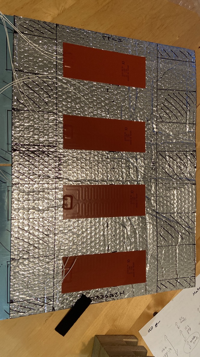
I put some aluminium lined bulb wrap on the bottom of the cupboard, and attached the heat pads to this. I then put an aluminium plat on top to spread the heat,
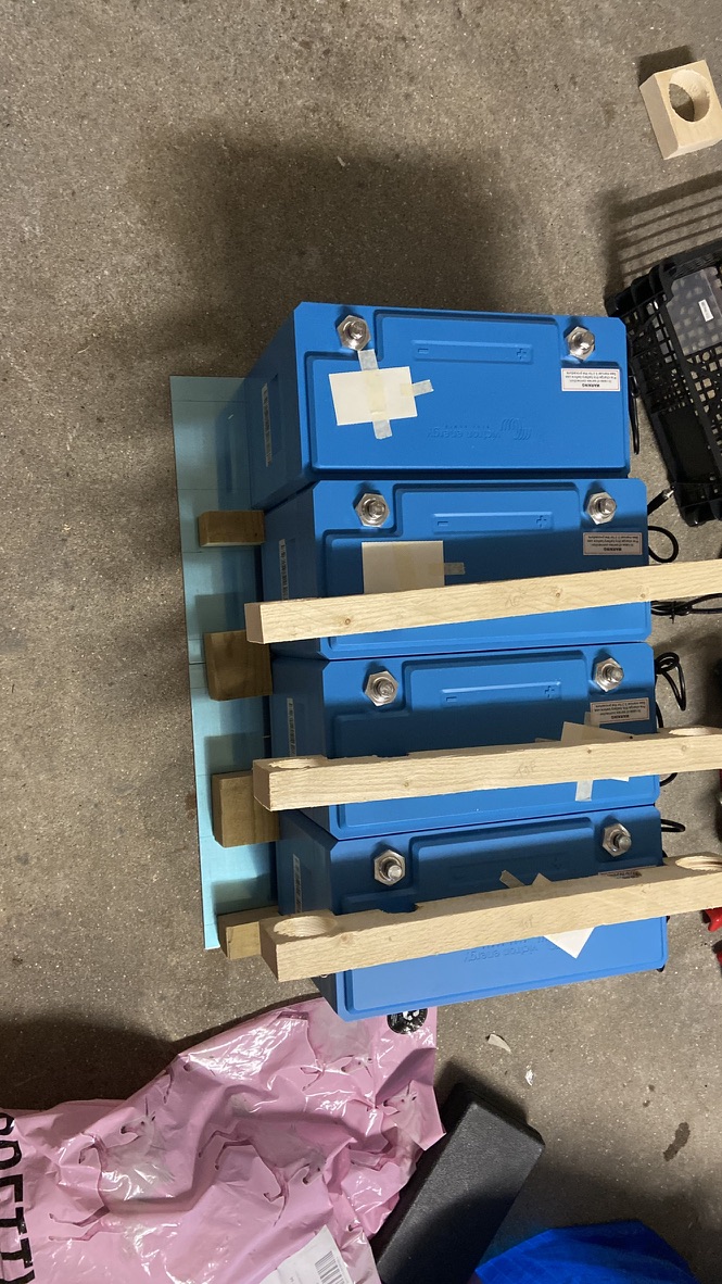
I then created some wooden supports to lift the batteries and leave an air gap between the aluminium plate and the battery bottoms.
Once installed wired to a relay, which switches on at a given temperature (7 degrees C) and off at another (10 degrees C). These will be tweaked based on findings over this winter, assuming I can get at the boat.
Photo of the heat pads attached to the aluminium bulb wrap and batteries on supports above the aluminium.

@Bathnm, if using DVCC and WS500s, I assume we do not need to run the separate temperature sense of the batteries to the WS500, as the Cerbo has this already, from the BMS?
About to install 2 on a large catamaran and the job is relatively simple one if this is not required. CAN network alread exists in each engine room at MPPT's, just need a crossover cable from each MPPT to each WS500.
Correct, there is no need for the battery temperature sensor. The BMS should signal a charge disconnect if the batteries get cold. That will be passed on through either the BMS Can messages or the feature in wire connected to charge disconnect. Note that the Cerbo GX and DVCC does not control the WS, it is controlled by the CAN messages direct from the BMS. In my case a Lynx Smart BMS is what the WS is getting charge messages from. If you have a VE.Bus BMS (v1 or v2) then you MUST make sure the feature in is connected to charge disconnect as that is what will stop the charge,
Hi Valden, I do have to Mastervolt with Masterbus as well :). I switch it of via an additional relay behind the battery protect. (Use that for the Genset as well). Were are you based? I've been fiddling for two days with a great mechanic and we got it perfect setup now. My first alternator is for the starter and bow thruster and is completely separated from the Victron setup.
Hi Gert. If I understand correctly, you are switching your Mastervolt alternator on and off manually, with a relay. I think I could be comfortable with this approach, provided the sudden switch off doesn't throw a nasty voltage spike into the system.
It's also interesting to think about how you have your two alternators set up, one for the engine start and bowthruster batteries, and the second for the Victron lithium setup. I'd love to see a wiring diagram of this. :-) Thanks for these ideas.