question

Todd Landfried avatar image
Todd Landfried asked

Are these reasonable readings for a Multiplus SOC shutdown?

I went out of town for several days and after three unplanned cloudy days, the system shut down as expected. What wasn’t expected was the readings when I got home and turned on the generator to charge the batteries. The first image below shows what the status was when I first turned it on. As you can see, the SOC is 41% after about 15 minutes of turning the generator on.

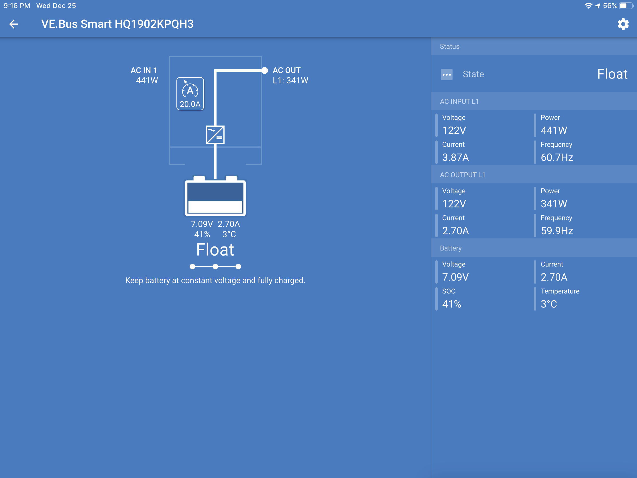
I was wondering why it was floating if the batteries were at 41%. After 90 minutes of no change, I started looking into why the Multiplus was floating instead of bulk charging. I found a couple of messages in the Community that suggested switching it to “Charge only” as a way to reset the Multiplus. So I did and it switched to absorption mode (at 9:11pm).

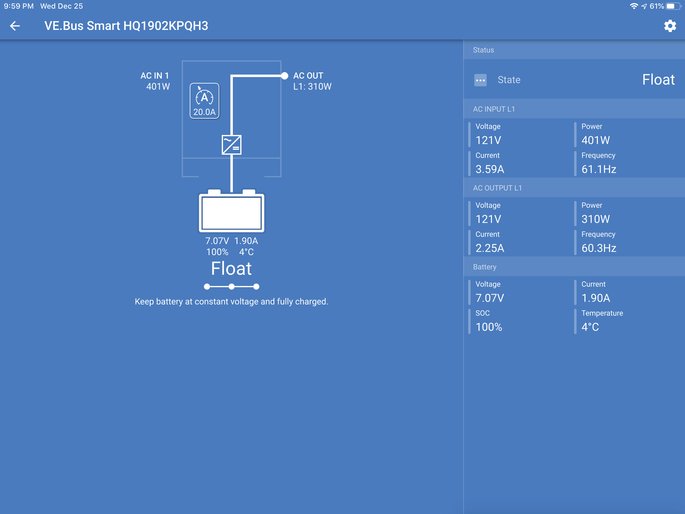
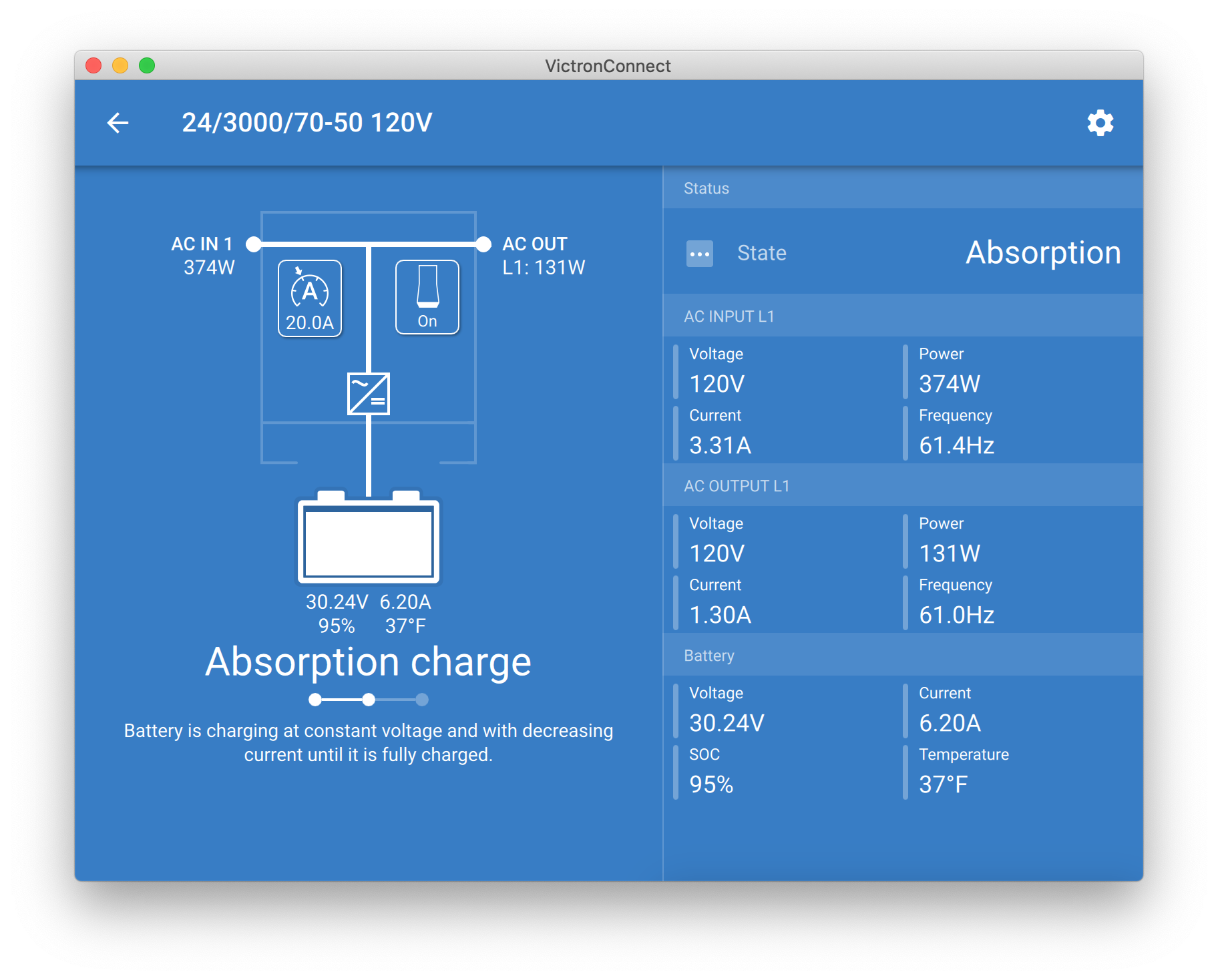
Immediately after doing that, the next reading I got was 85% SOC. Literally five minutes later, I got the following: 100% charge and back to Float at 9:59pm, for a total elapsed time of 48 minutes.

So my questions are:

  1. Is it to be expected that a system that was shutdown due to SOC settings should go from 41% to 100% in 48 minutes?
  2. Was it some kind of hiccup in the system that I needed to change it to Charger Only for it to go off Float to Bulk and then Absorption charge?
  3. If this is abnormal, what do I need to do to get a better understand and control of this behavior?
  4. Are there settings I need to change?

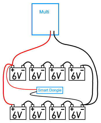
The battery bank is eight 6v 385ah batteries in series/parallel at 24v.

Thanks

Todd

Multiplus-IIbattery chargingGeneratorSOCfloat
img-0261.png (384.0 KiB)
2 |3000

Up to 8 attachments (including images) can be used with a maximum of 190.8 MiB each and 286.6 MiB total.

1 Answer
JohnC avatar image
JohnC answered ·

Please firstly explain where your 7.07V battery V is coming from. How can that be?


17 comments
2 |3000

Up to 8 attachments (including images) can be used with a maximum of 190.8 MiB each and 286.6 MiB total.

Todd Landfried avatar image Todd Landfried commented ·

Don‘t know. The smartdongle is connected exactly as instructed and thats the reading it’s providing.

0 Likes 0 ·
Matthias Lange - DE avatar image Matthias Lange - DE ♦ Todd Landfried commented ·

You should use a multimeter to messure the voltage at the battery connections at the Multi.

Or do you have connected the VE.Bus smart dongle to + and - of one of your 6V batteries?

0 Likes 0 ·
Todd Landfried avatar image Todd Landfried Matthias Lange - DE ♦ commented ·

The latter, because that’s what the instructions I saw said to do. Is that wrong?

0 Likes 0 ·
Matthias Lange - DE avatar image Matthias Lange - DE ♦ Todd Landfried commented ·

Yes, that's wrong.
You have to connect the dongle to the same points where the Multi is connected.

I'm suprised that the dongle is working with such a small voltage.

0 Likes 0 ·
Todd Landfried avatar image Todd Landfried Matthias Lange - DE ♦ commented ·

To be clear, do you mean inside the Multi or on the batteries? How does that square with their diagram?

0 Likes 0 ·
Matthias Lange - DE avatar image Matthias Lange - DE ♦ Todd Landfried commented ·

It should be like this:

0 Likes 0 ·
Todd Landfried avatar image Todd Landfried Matthias Lange - DE ♦ commented ·

The wires on the smart dongle aren‘t long enough. How do you extend them? Why can‘t I connect it to the two unused connectors inside the Multi?

0 Likes 0 ·
Warwick Bruce Chapman avatar image Warwick Bruce Chapman Todd Landfried commented ·

Ps. I extended mine using an Anderson power pole connector for easing connect and disconnect of the “extension” which I only made to the negative lead.

1 Like 1 ·
Todd Landfried avatar image Todd Landfried Warwick Bruce Chapman commented ·

What does that look like? Can you post a photo?

0 Likes 0 ·
Matthias Lange - DE avatar image Matthias Lange - DE ♦ Todd Landfried commented ·

The original wire are connected via screw terminals, so you just disconnect them, connect wires that are long enough and add a fuse in the + wire near the battery.

Connected to the batteries you will have the actual battery voltage.
If you connect the dongle inside the Multi you maybe will have a voltage drop across the cables from the batteries to the Multi.
But if the wires are thick enough this can also work without problems.

1 Like 1 ·
Todd Landfried avatar image Todd Landfried Matthias Lange - DE ♦ commented ·

Thanks for of the help. The wire that comes with it is fused on the + side. Are you saying that as long as the wire is the same gauge as the original I can connect them?

0 Likes 0 ·
Warwick Bruce Chapman avatar image Warwick Bruce Chapman Todd Landfried commented ·

The reason it must be connected as per @M.Lange’s diagram is because the voltage sense will only be accurate when connected to the batteries.

By connecting to the multi, the voltage sense will be out because of the additional resistance of the wiring, fusing, lugs and connectors between the battery and the multi.

Additionally, if you want to use the temperature sense on the dongle, it must be physically mounted one on of batteries for the sensor to work.

0 Likes 0 ·
Todd Landfried avatar image Todd Landfried Matthias Lange - DE ♦ commented ·

I just took this screen shot of the full app. The voltage looks better than the dongle.

0 Likes 0 ·
Matthias Lange - DE avatar image Matthias Lange - DE ♦ Todd Landfried commented ·

For a 24V system 30V are to much, you should now check your charger settings and the datasheet of your batteries.

0 Likes 0 ·
Todd Landfried avatar image Todd Landfried Matthias Lange - DE ♦ commented ·

The manufacturer sent me the settings...

0 Likes 0 ·
kai avatar image kai ♦ Todd Landfried commented ·

30v sounds in the right ball park? 37F ~= 3C which means the voltage should be bumped up re: tempco

0 Likes 0 ·
JohnC avatar image JohnC ♦ Todd Landfried commented ·

Yeh, perhaps try to sort this first, before relying on downstream soc readings which may/may not derive from it in some way..

0 Likes 0 ·