question

andres Hs1 avatar image
andres Hs1 asked

[solved] Please help: False low battery alarm - 12V LifePO4 (2P4S)

Hi all


I am having some strange Low voltage alarms thrown by the Multiplus when drawing high amps.

The system is installed in a boat with:

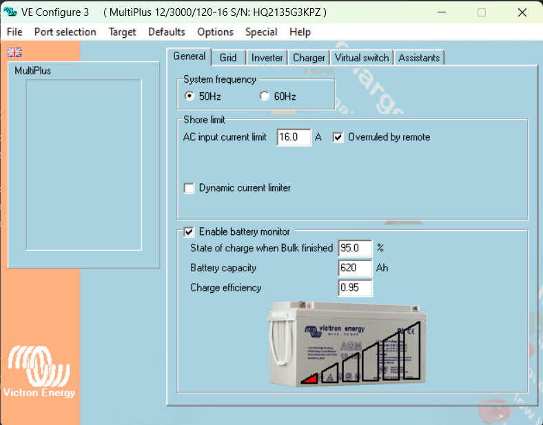
- 12v/3000/16Amp Multiplus

- 2 x MPPT

- 1 x Orion DC-DC

- Cerbo GX

- SmartShunt

- TaoBMS

- 8 x 310amp PRISM cells set as 2P4S for a 12v battery


The system was setup about a year ago, it has never been a problem cooking with the induction hob and drawing over 150Amps.

When the batteries are resting, these rest at around 13.3v, and when drawing over 100amps, these deeps below 13V, sometimes around 12.8V. And this is causing the Multiplus to throw a "Low Battery alarm" and restart.

As you can see in the screenshot below, there is a reset event every time the draw goes to around 100amp.multiplus12v-lowbatt-false-alarm.png

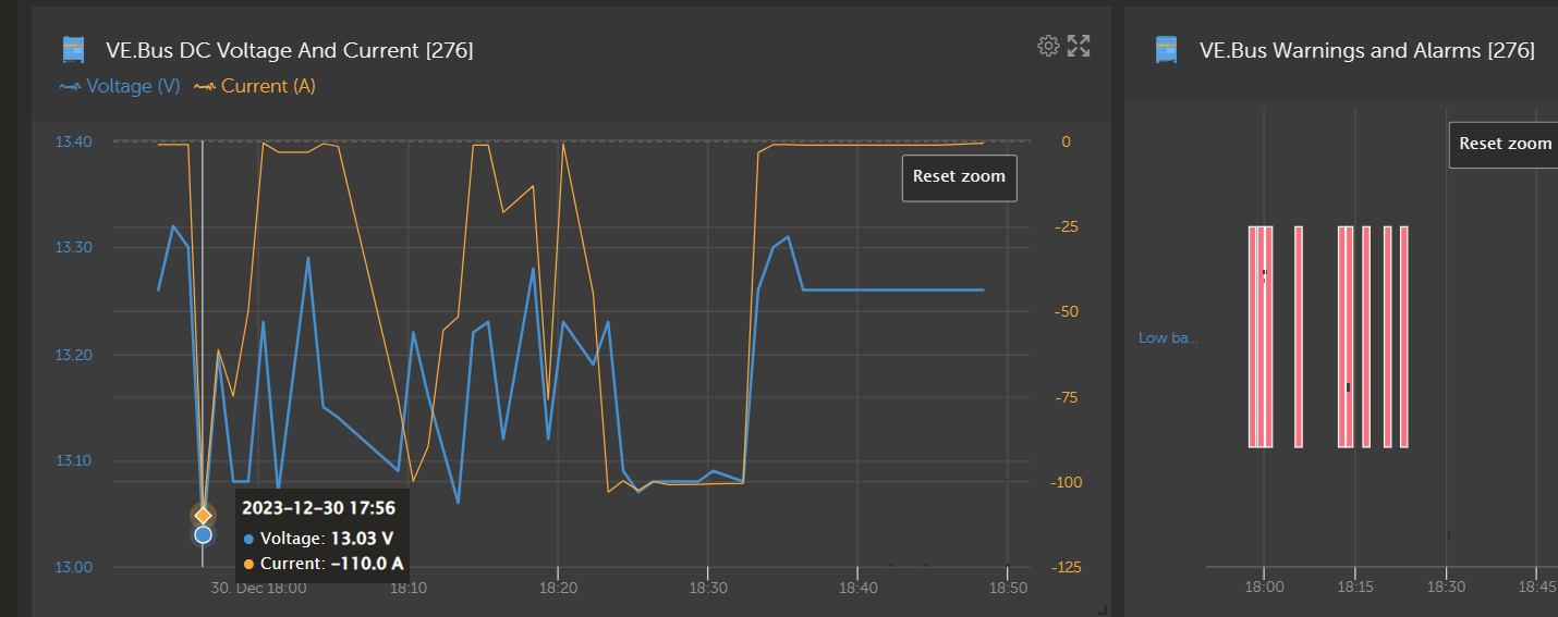
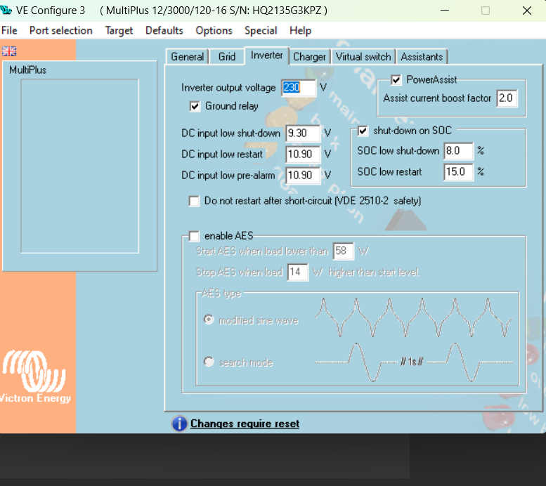
I have been checking the configuration of the system and I cannot see why this would be happening. Note that I have not setup any ESS assistants.


multiplus12v-veconfigure-2.png


multiplus12v-veconfigure-1.png


I have also checked the alarms setup in the SmartShunt and these are set to when the voltage drops to 12.4, and as you can see in the VE.Bus screenshot, the voltage never goes that low. (I was observing in realtime, and never went below 12.83v)


What am I missing?

What should I be looking at?


Thanks in advance for your help


Regards

Andres

Lithium Batterymultiplus ve.buslow battery warning
2 |3000

Up to 8 attachments (including images) can be used with a maximum of 190.8 MiB each and 286.6 MiB total.

4 Answers
andres Hs1 avatar image
andres Hs1 answered ·

Hi all

I think that it is worth giving an update

Today, I have finally had time to investigate the issue and I was shocked, and embarrassed, once I discovered the problem....

Some weeks ago I installed a 2A @ 12V fan in the battery compartment triggered at a 3 degree difference between cells. The power source for this fan comes from the same bus as the power source for the BMS and the CerboGX.

Now, it seems that the wire I used to power the bus is not sufficient and when the fan kicks in the CerboGX detects a drop and cuts the Inverter....

Once I turned off the trigger I was able to boil water for over 30 min drawing over 120AMPs and a peak of 139AMPs with no issues

So the solution is to add an additional power bus and segregate the power source for the BMS and the CerboGX, from the sources to the fans and solar panel relays

Cheers

Andres

2 |3000

Up to 8 attachments (including images) can be used with a maximum of 190.8 MiB each and 286.6 MiB total.

Alexandra avatar image
Alexandra answered ·

@andres Hs1

Chances are the shunt is near the battery, the voltage drop is at the inverter terminals. The logging is too far apart to see the actual peak voltage. 60 seconds allows for a lot.

Run the big load with a decent meter on the terminals you will probably see it then.

Might need to beef up the battery cables. Do you meet the min recommended size for the distance they are running. Didn't look at the manual but it will be close to 95mm².

Since it isn't a new install maybe check out the torque on the DC side and make sure everything is correct there.

2 |3000

Up to 8 attachments (including images) can be used with a maximum of 190.8 MiB each and 286.6 MiB total.

andres Hs1 avatar image
andres Hs1 answered ·

Hi @Alexandra

Thanks for your reply.

When we did the installation we doubled up on the wiring ( 2 wires of 90mm2 for live and same for neutral).

There is about 60 cm of wire between the batteries and the multiplus. And the strange thing is that is has started to fail this weekend. Last time I was on the boat (5 weeks ago) we were cooking drawing over 150amps with no issues.

And the only changeI did to the system over this period was to install the CerboGX Large OS and the GuiMods.

While I was cooking last night, I was monitoring the voltage displayed in the CerboGX realtime from the multiplus, and it never went below 12.83v. Do you really think that the voltage displayed in the Cerbo as coming directly from the multiplus will be different than if I measure myself? OK, I will go back next weekend and re-connect all terminals.

Regards

Andres

5 comments
2 |3000

Up to 8 attachments (including images) can be used with a maximum of 190.8 MiB each and 286.6 MiB total.

marekp avatar image marekp commented ·

@andres Hs1

Voltage could drop below 10.9V for less than a second. It is enough for MP to record it as a fault. Digital voltmeter may not even notice this drop and VRM is even worst in this regards.

Digital oscilloscope with memory would be needed to see this problem.

0 Likes 0 ·
andres Hs1 avatar image andres Hs1 marekp commented ·
Hi @MarekP

I will keep that in mind

thanks

0 Likes 0 ·
Alexandra avatar image Alexandra ♦ commented ·
When you added the Cerbo power where did you connect it?

The inverter is the one reporting the low battery.

Lugs stacked at all? Disturbed lugs is likely where to start.

0 Likes 0 ·
andres Hs1 avatar image andres Hs1 Alexandra ♦ commented ·
Hello @Alexandra


No, I installed positive and negative bus bars to avoid issues with stacking connections, and also to allow me modifying/replacing components without bringing the whole system down.

0 Likes 0 ·
klim8skeptic avatar image klim8skeptic ♦ andres Hs1 commented ·
@andres Hs 1 l had similar multiplus low voltage warning/cut out when running high current loads. Was running DVCC and SVS, thus the multi was reporting battery voltage.

Turns out I had a bad crimp on the cable between the bus and multi, dropping an extra .6v from the reported batt voltage.

Check your inverter cabling between the bus and multi under a high load for voltage drop and heating.

0 Likes 0 ·
Paul B avatar image
Paul B answered ·

As you are running a Lifepo4 battery there is a BMS inside that battery and the bms maybe connected to your cerbo via canbus , anyway one cell in the battery bank could be low and thus if that one cell drops to its warning/shutdown voltage the cerbo or multi will display a low battery warning. (of note is that the bms MUST be connected to the cerbo for this type of low voltage warning to occur)

I would sugest that you check and RE BALANCE all cells to 3.65 volts this is called a top balance,

if you do this by charging the battery at 14.5 volts and measure each individual cell voltage.

no cell should go over 3.65 v when all cells reach 3.65 volts then the battery has been topped balanced.

this may require you to take the top off the battery, it would be very handy if the battery have a bluetooth compatible bms. The TAOBMS should have bluetooth compatablity so readup on the tao manual as to how to read the cell voltages, the CERBO will show the high and the low voltage usually under the TAO attached BMS controler.

2 comments
2 |3000

Up to 8 attachments (including images) can be used with a maximum of 190.8 MiB each and 286.6 MiB total.

Paul B avatar image Paul B commented ·

Another thing is that you should top balance once a month to avoid this sort of cell imbalance. for balancing to start a cell must usually reach 3.5 volts 4 x 3.5 is 14v or any combination, anyway readup on cell balancing. NOTE you should be able to see the graph in the VRM by selecting the TAOBMS and then selecting the high low cell graph, the only issue in the graph is that we dont know which cell its refering to.

0 Likes 0 ·
andres Hs1 avatar image andres Hs1 commented ·

Hi Paul

I have independent PRISM cells connected to my BMS which connects to the Victron system via the CAN bus.


I have been closely monitoring the cells and I cannot see any of them dropping.

The TaoBMS is also helping to keep the cells balanced at all times.

but anyway, given that I will be taking the system apart, I might as well do a top balance at the same time

0 Likes 0 ·

Related Resources

Additional resources still need to be added for this topic

Battery Compatibility

Did You Know - How to create a battery profile for non-Victron batteries?

Additional resources still need to be added for this topic