question

Albert de Jongh avatar image
Albert de Jongh asked

Multiplus II 48/3000 - inaccurate voltage reported, continuous charging / discharging at 100 %

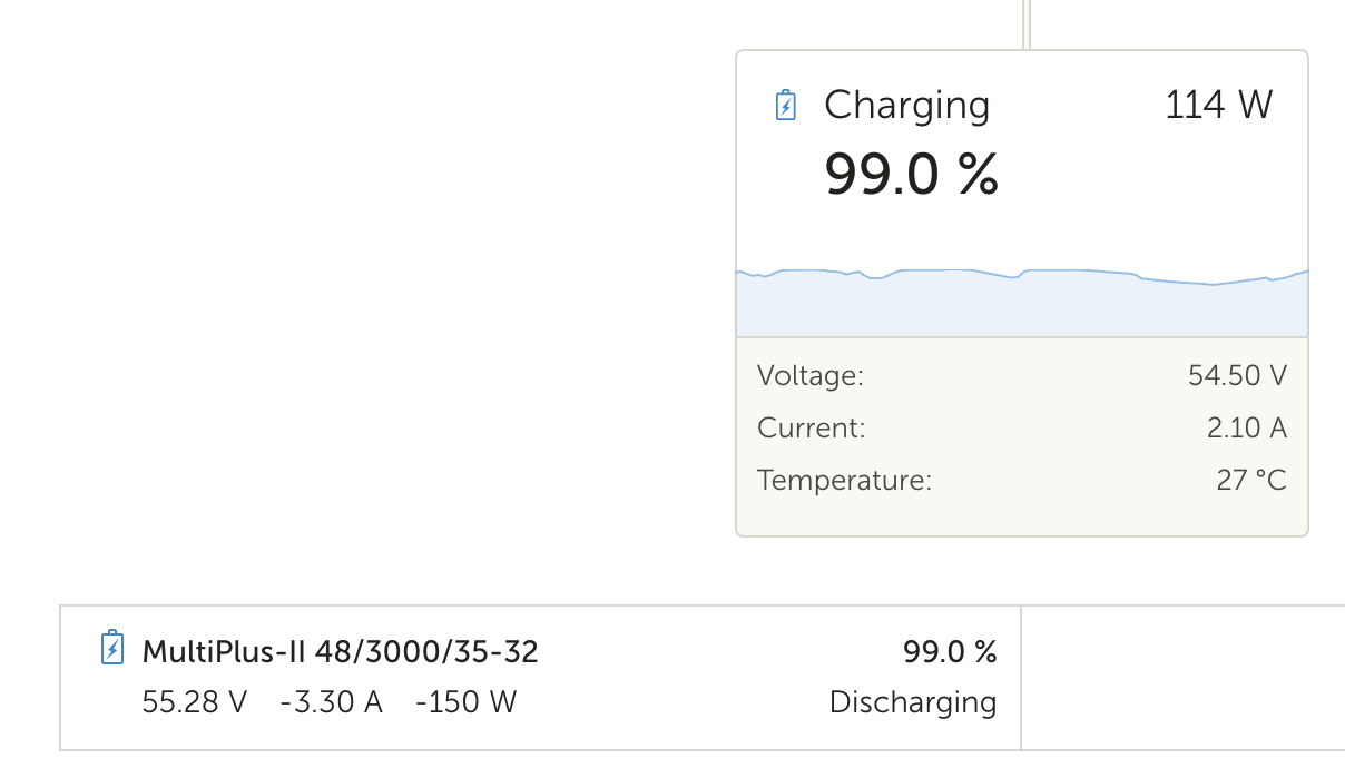
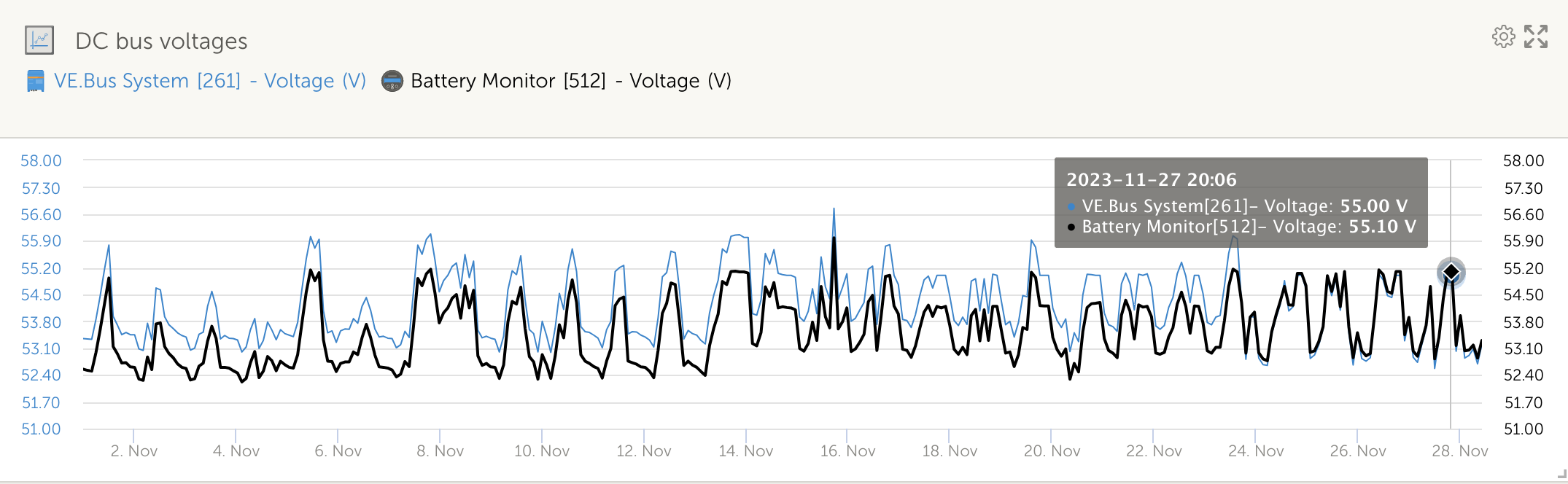
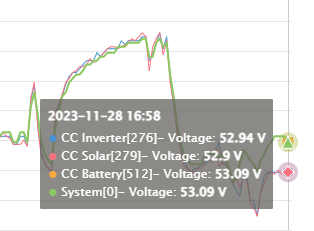
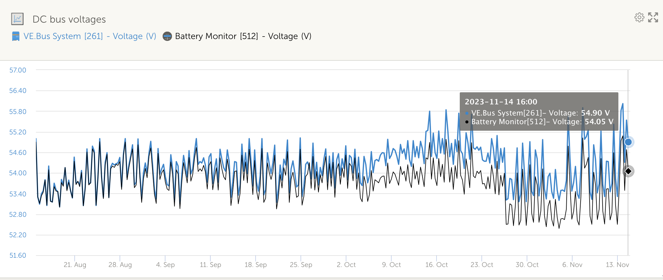
I have noticed the following - over the last three months the Multiplus measured voltage has been drifting up. At the beginning of August the Multiplus voltage was within 0.05V of the BMS voltage. Three months later the Multiplus voltage is now 0.8V more than the BMS voltage. I have confirmed with a quality multimeter that the BMS voltage is indeed measure correctly.

1699995462171.png

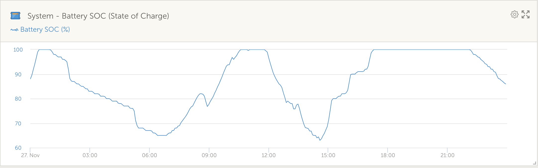
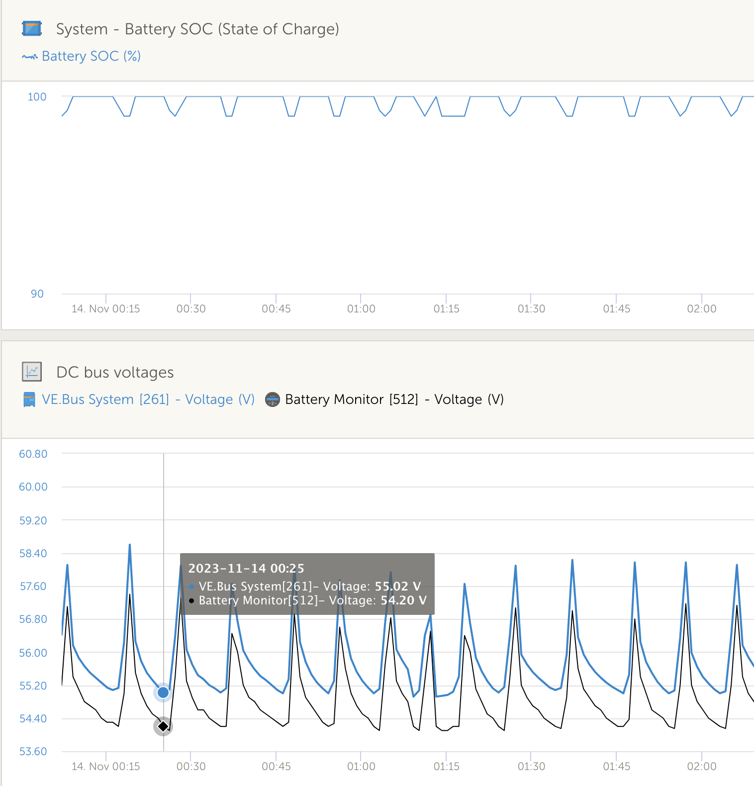
This has some peculiar side effects in that when the battery is 100 % charged the system starts oscillating between 99 and 100 % - I presume because the Multiplus is letting the battery voltage drop too far because it thinks it is really higher.

1699995574226.png

Has anyone else had this issue?

The closest I could find is in this thread: https://community.victronenergy.com/questions/138444/multiplus-voltage-differences.html - user @anieuwstadt had a similar issue that was apparently an "inverter hardware" issue.

Multiplus-IIvoltagebattery system voltagecharge current limitaccuracy
1699995462171.png (441.9 KiB)
1699995574226.png (314.0 KiB)
5 comments
2 |3000

Up to 8 attachments (including images) can be used with a maximum of 190.8 MiB each and 286.6 MiB total.

anieuwstadt avatar image anieuwstadt commented ·
Hi, I was not given specific details of the issue found on the hardware, but in my case, I suspect that an internal reference voltage was drifting. The Vref is recalibrated when the inverter firmware is updated or re-installed.
0 Likes 0 ·
Albert de Jongh avatar image Albert de Jongh anieuwstadt commented ·
Ok - so did they give you back the same inverter, or just updated the firmware?
0 Likes 0 ·
Alexandra avatar image Alexandra ♦ Albert de Jongh commented ·
On the GX in DVCC set the system will use the battery voltage for reference.

The DC bus voltages can go up when it is processing mppts power etc. particularly if the battery is idle and ESSIng of grid

0 Likes 0 ·
Albert de Jongh avatar image Albert de Jongh Alexandra ♦ commented ·

I am not sure about this. With the BYD battery shared voltage sense (SVS) is force disabled. I can also see that if e.g. I set the "Limit managed battery charge voltage" to e.g. 55.3V the Multiplus is using its *own* voltage to aim for that, and not the voltage from the BMS. See below:

1700122882979.png

0 Likes 0 ·
1700122882979.png (70.3 KiB)
anieuwstadt avatar image anieuwstadt Albert de Jongh commented ·
The inverter was changed as it continued to drift after recalibration.


0 Likes 0 ·
4 Answers
Albert de Jongh avatar image
Albert de Jongh answered ·

Answering my own question.

I asked around a bit (thanks @Warwick Bruce Chapman), and also found this thread: https://community.victronenergy.com/questions/196650/why-is-mppt-reporting-nearly-3v-higher-than-pylont.html

This particular post by @Guy Stewart (Victron Community Manager) was also interesting, as it mentioned vsense:

My system diagnostics page *before* disabling vsense -

You can see the "sense voltage" is very different from the terminal voltage.

And this is after disabling vense -

And, this is what my DC bus voltages look like now; you can see where I disabled vsense...

1701159567461.png


And, as expected - the oscillation of charge / discharge when the battery is at 100 % has now completely stopped.

1701159761058.png


So it appears there is something wrong with the vsense hardware / algorithm in my MPII. It does not matter too much since I have a LiFEPO4 battery with BMS though.


1701159567461.png (259.4 KiB)
1701159761058.png (103.6 KiB)
2 comments
2 |3000

Up to 8 attachments (including images) can be used with a maximum of 190.8 MiB each and 286.6 MiB total.

anieuwstadt avatar image anieuwstadt commented ·
Hi,


I was looking for a chart that showed SoC and the DC voltages at the same time. What one is looking for is the system going into self-consumption mode when the battery is full. When the battery reaches 100% SoC, the voltage is raised a little to prevent the consumption of energy from the battery. This voltage uplift can be seen as something going wrong, but it is intentional

Check the VE.Bus state. With Vsense turned off I have seen VE.Bus showing a Fault state.

0 Likes 0 ·
Albert de Jongh avatar image Albert de Jongh anieuwstadt commented ·
No faults on VE.Bus state. Basically because the MPII voltage measurement is more accurate the battery is not getting discharged once it reaches 100 % - and hence the discharging / charging cycle stops.
0 Likes 0 ·
Albert de Jongh avatar image
Albert de Jongh answered ·

In this case the Multiplus voltage is *always* 0.8V higher than the battery, and it has been getting worse over the last three months. This is an on-grid system.

1 comment
2 |3000

Up to 8 attachments (including images) can be used with a maximum of 190.8 MiB each and 286.6 MiB total.

Alexandra avatar image Alexandra ♦ commented ·

With DVCC it should be using the battery reference. If it has control that is likely the cause of the up and down

Have you checked your terminal torque and connections between the battery and the inverter?

Keep batteries charged will still make the DC bus a higher voltage as it will do that to make it the source of power. Since potential of some kind has to be created for flow.

How is the battery at that point is it cell balancing?

0 Likes 0 ·
Albert de Jongh avatar image
Albert de Jongh answered ·

What should my expectation from Victron be in this case - how much voltage inaccuracy is "too much" for this inverter? I have started talking to my distributor.

1 comment
2 |3000

Up to 8 attachments (including images) can be used with a maximum of 190.8 MiB each and 286.6 MiB total.

anieuwstadt avatar image anieuwstadt commented ·
I cannot speak for Victron on these matters. Please create a custom chart that shows SoC as well as the VE.Bus and BMS battery voltages on one chart. Also, time correlate a chart of the ESS state for the same period.
0 Likes 0 ·
anieuwstadt avatar image
anieuwstadt answered ·

This is odd, I get voltage variances when Vsense is disabled and perfect voltages with Vsense enabled.

On v506 firmware


Vsense disabled

1701183653815.png


Vsense enabled

1701183824241.png


1701183653815.png (26.3 KiB)
1701183824241.png (16.0 KiB)
2 |3000

Up to 8 attachments (including images) can be used with a maximum of 190.8 MiB each and 286.6 MiB total.

Related Resources

MultiPlus-II Product page 

MultiPlus-II Manual

MultiPlus-II 230V Datasheet 

VE.Bus Error codes

Additional resources still need to be added for this topic