question

rogio avatar image
rogio asked

ESS cycling the battery 10% of Minimum SOC above the SOC when solar does not cover the loads

Hello,

I would like to raise a question (or maybe three of them) to the Victron.

The main Question or more a complaint or how the report of "strange behaviour" should be called - in regards of loosing the battery round-trip energy and aging the battery "artificaly" during "darker days".

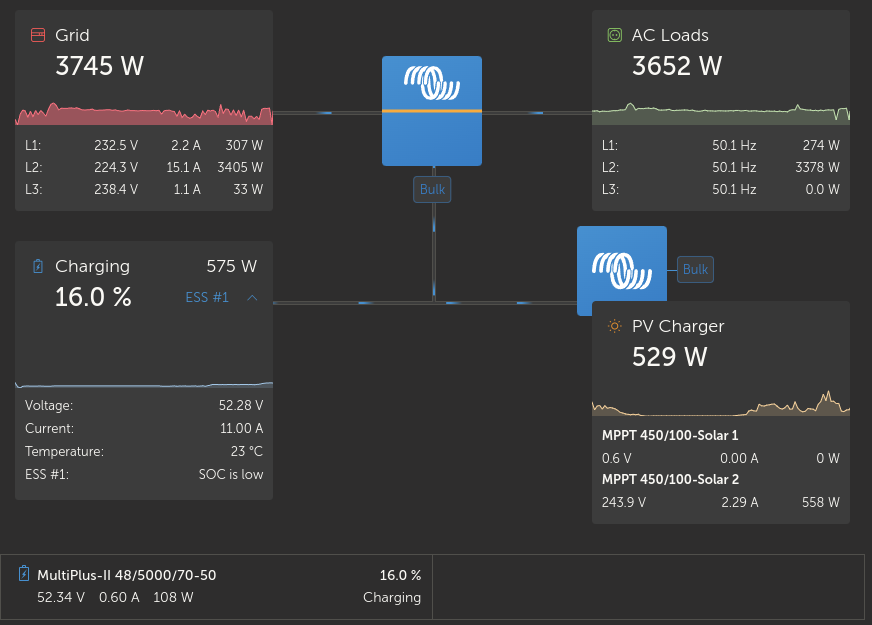
3phase EES system of
Cerbo Gx (fw3.10),
3x Multiplus 5000/48 70 (fw506),
4x Pylontech US3000C (with korona chips),
grid feed-in enabled, optimised without battery life,
"individual phase regulation" because of the local "per phase" metering,
SmartSolar MPPT VE.Can 150/70 rev2 v3.13,
SmartSolar Charger MPPT 150/45 rev3 v1.61,
SmartSolar Charger MPPT 150/35 v1.61,
external grid meter (ET340),
some loads between external grid meter and AC in (heat-pump to be exact)
critical load on AC out.


1) The "behaviour/problem" :

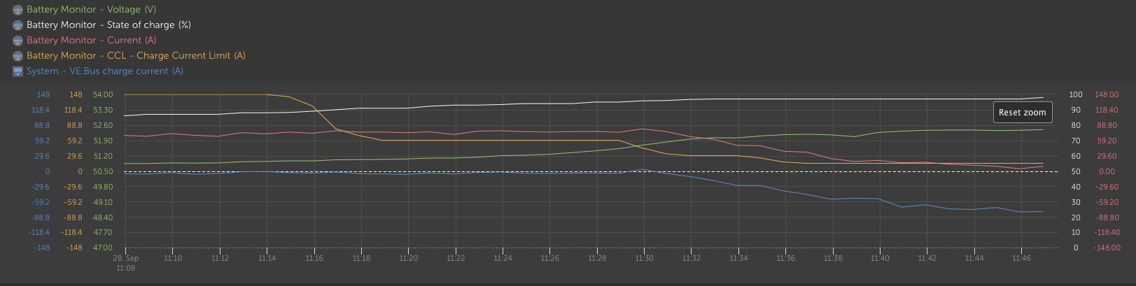
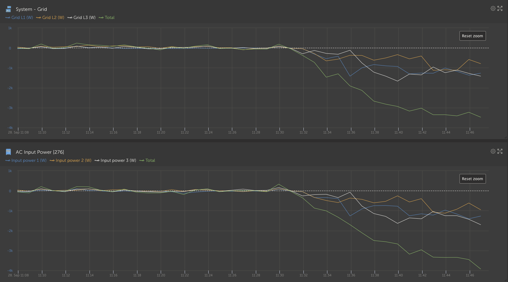
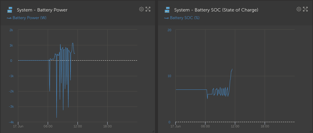
On the "darker days" - whenever the system is on "minimal SOC until grid fails" there is the "unwanted feature" of using the solar to charge the battery to "minimial SOC"+10% of minimal SOC. (do not know why..) Yes, it is "ESS optimized without battery life". And after this Minimal SOC+10% is reached the "freshly charge" is again taken from the battery and the battery and solar feed the loads, until the minimal SOC is reached again - then this theatre starts again and the battery gets again charged 10% up by solar, loads are again covered from grid. And again and again.


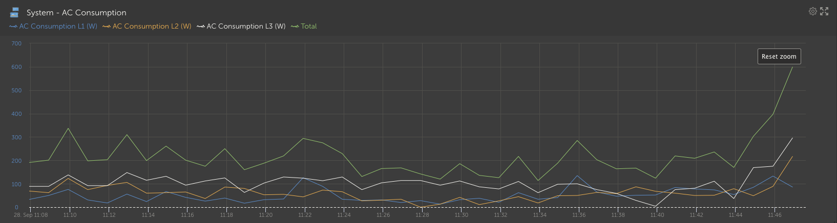
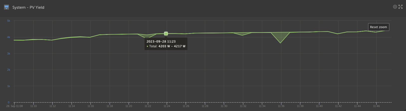
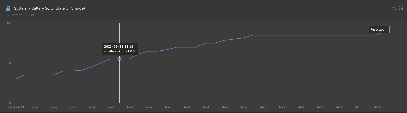
Example : (almost real life - darker day, not too high consumption): "constant" 300W DC solar input, 600W "critical" loads, Minimum SOC until grid fails 30%.

1.1) Starting with battery on the 30% SOC in the morning .. 300W used for charging the battery (why??), 600W from grid used to cover the loads (Why does not the system just cover 50% of the load with the DC connected MPPTS output and rest from grid, and leave the battery "sleep"??)

1.2) 33% battery SOC (meaning 30% + 10% of 30%) gets reached (as said charged by solar, but loads covered by grid ..)

1.3) Battery and solar are used to feed the loads - again until 30% min SOC is reached. (just discharging the "few minutes ago" charged battery charge.

1.4) The cycle starts from beginning.

Would this (unwanted charge/discharge cycle) last with the "actual battery bank capacity" for lets say 2 hours (for better numbers, in real it is shorter - like hour ..) - then 600W from grid would be used to cover the loads and 300W of solar would go to battery and the 2nd hour 300W of solar and 300W from that "now charged a bit up" battery cover the loads.


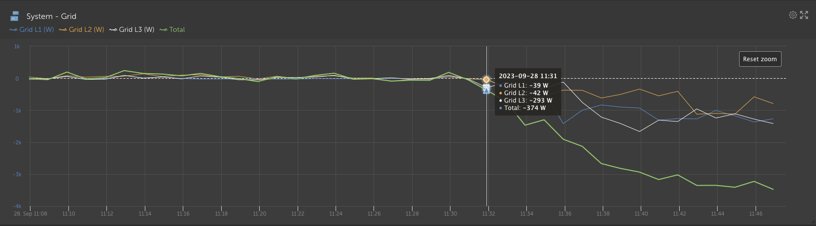
Wondering why this "buit in rule" has to be there - just "loosing the battery round-trip energy and aging the battery" (credits to @beat for the proper wording - not native english speaker here). Where when you look at the SOC or the "grid usage" graphs - it looks crap - like a lawn rake -_-_-_-_ (battery, and the grid is in inversion to it the whole day) - hour charging (and consuming the grid), hour discharging, through the whole day - "mini" cycle after cycle - just burning the energy with charging/discharging and cycling the battery. (sorry, not electrician or as deeply familiar with the "electrical part" of the system, just seing the "unexpected behaviour" as also the "broken" premise "loads first").

Where the documentation "all around" is stating a premise that the behaviour is simple "first loads, then battery, then feed-in .. " - not in this case.

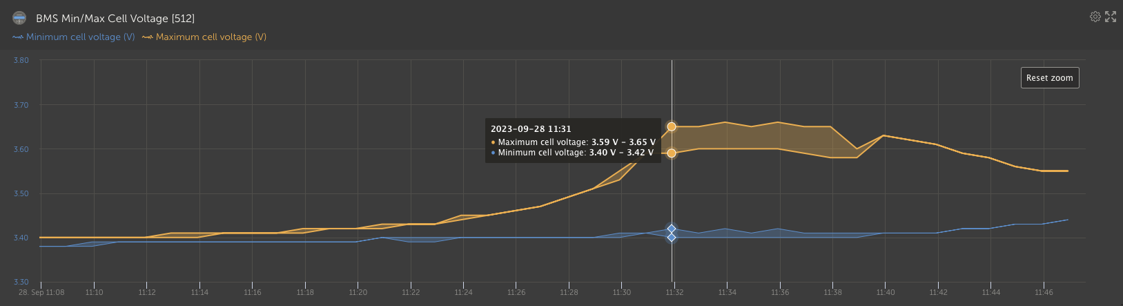
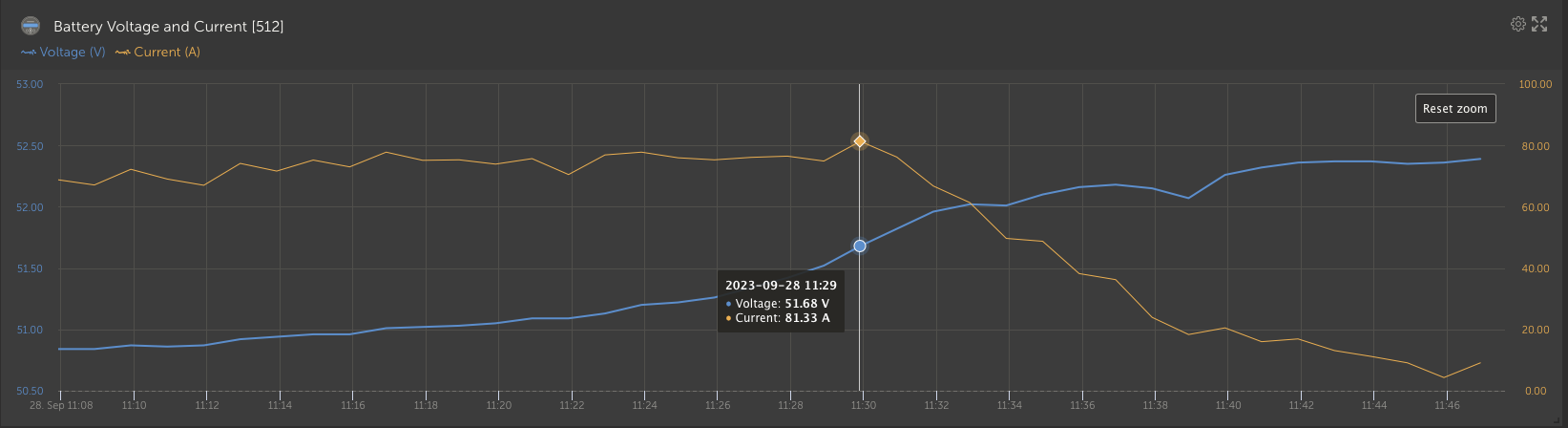
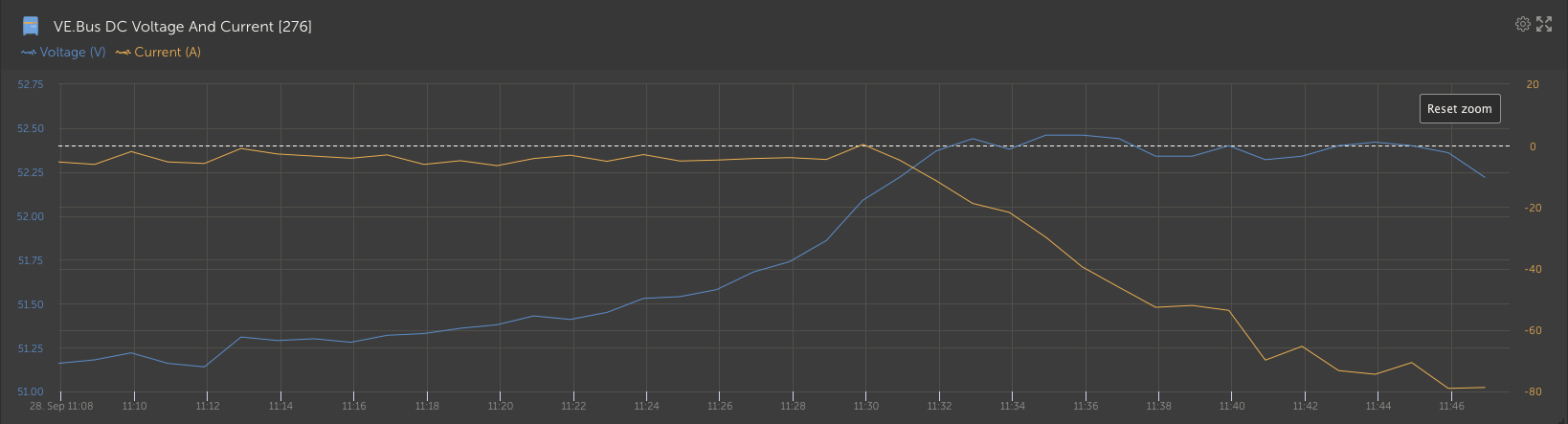
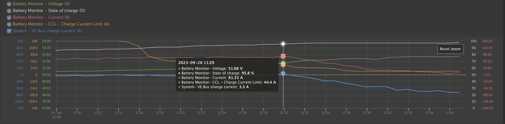
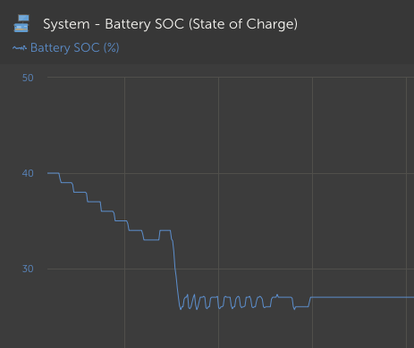
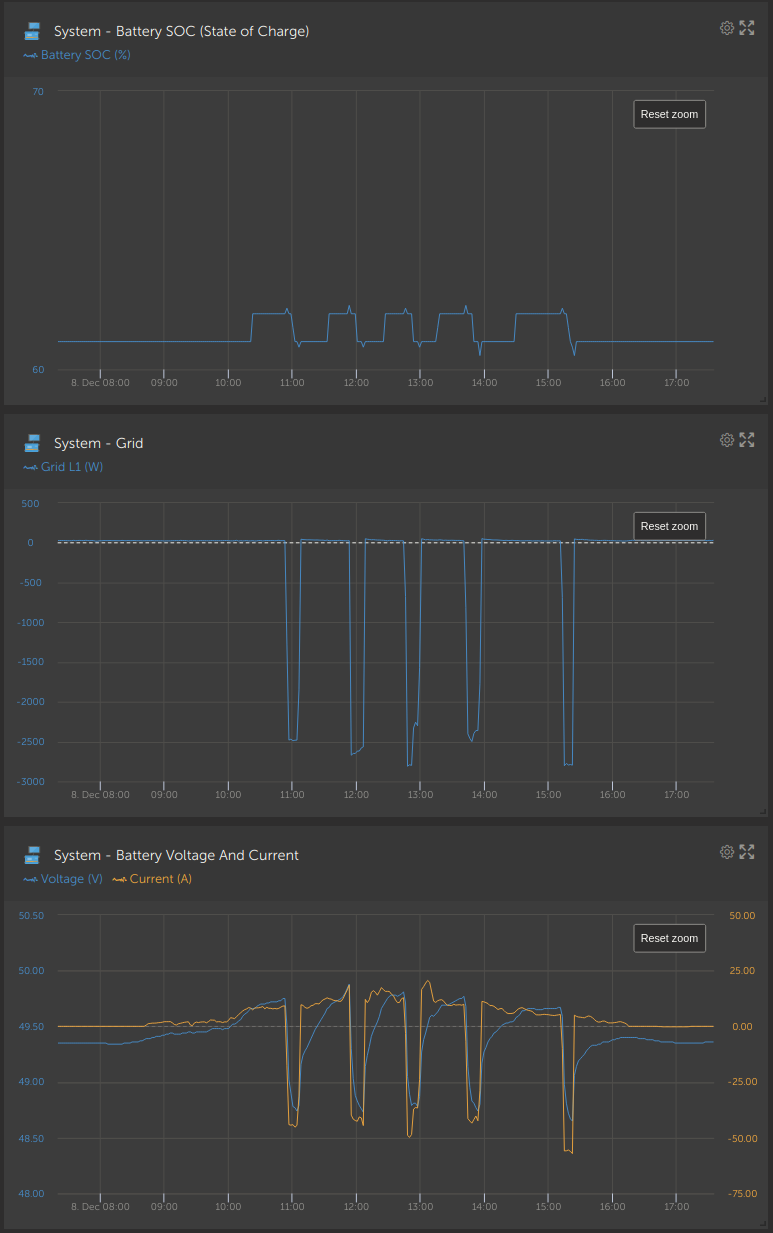
2) Where 2nd "tiny point" - based on recent try of "with battery life" set - also there is the behaviour a bit strange. Not only the "protection of virtual SOC" is provided, which is for sure nice (at least for lead acid), but also the "battery first, loads later" behaviour in the morning gets broken. (have choosen "with battery life" while trying to avoid/delay the "high voltage alarms" caused by "very slow Multiplus feed-in start" - causing too high charge current, even battery has minutes ago asked to drop it at the battery near to charged (~95 SOC), causing cell imbalance - probably as result of slow "multiplus reaction" after feed-in has been enabled - effectively "disabling" the MPPT throtling the gains. (the later (high voltage alarms) here is not a small issue either, but hope to have possible solution with dropping the charge voltage a bit - needs to be tested by the installer.)

Meaning in this 2nd point :

2.1) Problem the Sunny days - in the opposite, when setting (July this year - gathering the feed-in for "winter" based on grid contract, "without battery life") the grid DC feed-in (limited to 7K - limit never reached) - yes, it disables the MPPT throtling, fine so far. But for some reason the Multiplus does very very slow react on the battery bank BMS request to drop the charge current (around 95% SOC - still getting 2kW+) and only very slowly (and in up to 5 minutes delayed per step) starts and (still minutes later) increases the grid feed-in (in what it looks like 600W steps). (as user not having the chance to re-enable MPPT throtling, nor having insigt what, whether LOM, hidden "network requirements" or what is causing the Multipluses to take ages to "get rid of the surplus" to the grid. In end-result causing again "attack on the battery" - flooding it until cell imbalance and "up to 12 times high voltage alarms around the time of switch from "bulk" to "absorption" making the brick to deny charge (and high probably loose health..)

2.2) When setting the "with battery life" - have expected the system to "setup a virtual limit based on the daily solar gain to keep the battery better charged" (yes, the 80%SOC +-5% .. etc..) - but wondering now - why yes, one day ended on the "virtual SOC" .. but the next day morning starts with 5% battery charging (or more ??), before the solar is used also for loads .. This is somehow again "agains the premise of loads first, battery seccond".


So where is now the truth, why I cant get rid of the feeling, that the ESS with DVCC (and for user disabled (or editable, but ignored) limits and disabled shared stuff inside of DVCC - like "max charge current deactivated", MPPT throtling deactivated) behaves like the "battery enemy" - "high current", "unnecessary charging and discharging cycles" - and all that with "External control of the BMS" and "ESS#1", "ESS#2" ... Beside of that breaking some of the basic rules (which sound nice and promissing) described in the documentation.


3) And "last surprise" at the end - met the "Self consumption from battery" - "Only critical loads" option - wondering why does this work (according to documentation) only for systems with disabled feed-in ?? (as if during the night, where you would like to conserve energy for maybe critical loads, or "leave the non-critical ones to be covered by grid" the feed-in does not play any role (leaving out the dynamic ESS in my thoughts). And during the day - there is either enough solar to cover the critical loads, the non-critical loads, feed the battery and maybe even feed in. Without feed in - the "equation" seems almost the same - except maybe "battery flood" caused by "enabled but inactive feed-in" while having stopping extensive non-critical loads - which again seems similar to the 2.1. - "burning the battery". Missing somehow the point, where is the difference "not to discharge battery" for the non-critical loads - with or without feed-in enabled. (in perspective of non-critical loads between external grid meter and ac-in). And yes - with heat-pump as "non-essential" load - I would like (and was looking for - when reading about this feature) to leave it out from the battery cycle - as it would just drain the bits soo fast during the winter "dark" days.


Really thank You - for the energy and effort in case someone kept reading my long post until here.


battery chargingESSBMSPylontechcharge current limit
3 comments
2 |3000

Up to 8 attachments (including images) can be used with a maximum of 190.8 MiB each and 286.6 MiB total.

Alexandra avatar image Alexandra ♦ commented ·

@rogio

Try making several smaller posts. Or speak to a local dealership. Your problems are installation related.

And with a very under sized battery bank instability is definitely expected. There is a reason why the minimum requirements are stated.

0 Likes 0 ·
rogio avatar image rogio Alexandra ♦ commented ·

Thank you for your fast reply, not sure whether helpful in actual situation.

Yes, I am in contact with installer and with local dealership technician. Part of the problems (the battery "10% over SOC cycles") was marked as "standard" by the dealership technical specialist (sorry for having problems to fully trust to that few months old statement - regards the battery cycling - unless it comes from Victron itself - or gets part of the documentation.) (The technicians "this repetitive charging is longer in the wild, ... has to be standard" does not sound "too official").

The other part - the "Multiplus delay in initiating Feed-id" since Feed-in allowed in July - the technician is scrubbing his head around and except upgrading the firmware tried to tweak some values (like switching the not present AC connected feed-in off (useless of course), or toying around with max charge voltage in the dvcc increasing the value, which of course is limited with dvcc, and does not give much sense... So much about like two weeks ago when he took the phone and reacted. (somehow my request to disable LOM for test - when there is external "protection" installed has not made it through yet, and his idea of opening Victron case high probably did not become reality).

And from the installer I heard also like "yes, noticed "high voltage" alerts also in some other installations, but have not yet figured out .." thus I am kind of searching around, trying also (I hope they try too...) to find some help, solution, or maybe gain vendor attention or comment in regards of the behavior.

0 Likes 0 ·
rogio avatar image rogio Alexandra ♦ commented ·

So you mean 4x US3000C for 3 phase system (3x MP2 5000), with ~8kWP roof (half south, half west) is under sized battery bank?

(Still one brick more - I asked for, than the installer has designed and what is usually taken on 2000 Pylons (3pcs). Not as many instalers visible around but 5+ of such "businesess" just push 3x Pylon 2000 and some even in same rack "all in one", all of them with 3 pcs.)

And sorry, have seen "recomended sizing" for one phase inverter setup. Not for 3 phase, nor for 3phase with US3000C - based on what are you please using the "very under sized battery bank"? - a document reference or a bit of math would be really welcome.

Having 3 pcs of "theoretically" 5K inverters does not mean they ever have run (all of them) with full power (but sometimes you may have more paralel loads on one phase and 5K on the phase is better than 3K then), ... As for the 7.8kWP roof - just a theoretical number and still in extend of 4pcs recomended charge current.

And yes, also the grid is part of the local instalation, .. etc.

Thanks for you reply anyway - as most of such questions in the past here died on "quiet", but no - have not noticed any "undersizing" during normal March-October operations. But problems with "current overpressure and Multis taking their time" when grid feed-in is enabled. and strange in batery, out of it yes.

0 Likes 0 ·
3 Answers
beat avatar image
beat answered ·

I agree with @rogio to make smaller posts. Maybe close this, and make 3 separate posts for your 3 issues, or at least move parts 2 and 3 to separate threads.

I do not agree with @rogio that Part 1 is related to battery size or wrong configuration, I have enough batteries (6 US3000C for 1 MP II 5000), I'm trained and have a properly configured system, and see same cycling issue here when around minimum SOC, and solar power below loads, it is obviously an algorithm issue which is all-or-nothing:

There are basically 2 working modes (above SOC full priority to loads, and below SOC full priority to battery), probably with a 10% hysteresis.

Instead of the hysteresis, a third mode within the hysteresis, with priority to loads without battery use would fix this behavior.

9 comments
2 |3000

Up to 8 attachments (including images) can be used with a maximum of 190.8 MiB each and 286.6 MiB total.

rogio avatar image rogio commented ·

There we fully agree @beat on the battery "count" - also do not feel that the "battery bank could be so big" to accept any current at end of the charge cycle, maybe it could minimise the presence, extend a bit the time (depending on the actual irradiation) or give a chance for the 50mA (or how much) to balance within 10+ batteries :-)

btw @beat - one point - the number of MPs does not play role in this case - it is the "roof"/"battery" balance the critical part here in my recent understanding. (in my case the "theoretical" 7.8kWP (feeding at those alerts 2kW+) with "minimal loads" (~300W), where the Multies "fetch the current" too late to feed-in.

(where as with charge, discharge, MPPT - all was fine - until the feed-in was allowed - since then at the end of the charge cycle the "unlimited" MPPTS are "drowning the battery" (which is high probably not properly balanced after like 40% SOC charge after night consumption discharge) and multies are probably "negotiating" with grid about possible feed-in start/increase taking 5+ minutes - while the batery in the meantime drops and drops the "allowed charge current" in DVCC.)


The "And with a very under sized battery bank instability is definitely expected. There is a reason why the minimum requirements are stated." comes from @Alexandra - still waiting for some kind of math, or link to example - why she replied this way.


So far I have only seen the AC coupled 1:1 and later also the AC coupled related battery sizing ..


Would not like to play "a game" with the actual 95 followers and "accept the solution" and open 2-3 new posts.
a) all is bit about Pylon/BMS
b) at least two points "side/root causes" are co-caused by "allowed feed-in"

0 Likes 0 ·
Alexandra avatar image Alexandra ♦ rogio commented ·

@rogio

Your installer didn't do the math. Not sure how I became responsible for that.

https://www.victronenergy.com/live/battery_compatibility:pylontech_phantom#minimum_battery_sizing_recommendations

1 X US 3000C has a discharge continous recommend amount of 37A. You have 4. That is 148A. Enough battery for 1.5 X 5Kva inverter. (5000÷48v is 104A.) I assume then the system is sized using the peak (not nominal amp) of the battery rating. Poor design.

pylontec communicate with the system, telling it to charge or discharge etc. The inverters will want more than the batteries are designed to give. Weird behaviours always result.

When you have feed in activated it ignores battery limits, all the more reason to make sure the battery bank is big enough to sink the currents being processed.

0 Likes 0 ·
rogio avatar image rogio Alexandra ♦ commented ·

You became not responsible for my installer faults (this not being one), you became responsible for your posts. Writing something - from time to time requires adding also a "proof" and firstly also understand the matter - maybe not properly explained by me or lost in loong text. (where what you wrote about is not the problem - to be the 2nd part why I asked for details)


The 25A is meant for the 2000 Pylon series, 37A is the recomended for US3000C - the first point to correct here.

So it would be 4x37=148 - what is also the BMS charge/discharge limit communicated to the dvcc. (before the bateries near to 95% or near depletion, and some temperature .. etc.)

There was never a problem in the line "inverter - battery" - please stop playing the game "batery is undersized for inverter", thank you!

The Inverters have never requested 15kW and I hope they never will - following the max charge/discharge values (and even then it is also their "peak" limit, not regular ..) :-)


The problem is and starts with DC coupled MPPTS "not reducing the solar input", while the battery is "almost charged" and the Multies "are sleeping or negotiating with the european union for 5+ minutes about the chance to feed-in the overflow as the battery is almost full and the MPPTs are still pushing" (as the "enable-feed in" kind of disables the MPPT abililty to throtle the roof current)


There is not "lack of current" - there is the opposite - overflow of current, where the MPPTS push "damn too much to the battery" (being almost full) or better to the battery/MPPTs/Multies bussbar and the Multis take bit too long to arrange "the papers" for grid feed-in. (a bit of joke) Thus the "additional energy" not wanted by the battery anymore is stil pushed to the battery.

0 Likes 0 ·
beat avatar image beat Alexandra ♦ commented ·

@Alexandra, in your last paragraph, you wrote interestingly:

> "When you have feed in activated it ignores battery limits," ...

I guess "it" means the MPPTs, under "external control" by the GX device ?

You seem to be right, it looks like it's doing quite exactly that, ignoring battery limit given by BMS. And actually, the GX device is not only not respecting battery charging limits by not throttling the MPPTs (or in some cases, e.g. when turning on grid feed-in, by unthrottling the MPPTs in advance without increasing simultaneously the Multi's inverting power), but even not respecting the AC-IN feed-in limit either.

If it would be for miliseconds, it would be ok, even a one second power balancing could be understandble for system stability. But certainly not for 5+ minutes.

But can you please help me find where that would be specified/written in documentation ? I haven't seen that in the Victron manual nor docs yet, only in these forums from time to time.

And much more importantly, why would that be needed? The GX device knows what the Multis are feeding-in or not, and can adjust the MPPTs maximum power very quickly anytime. It does that quickly when you suddenly increase load on AC OUT, or a bit slower but within a second or two (not 5 minutes) when you change the feed-in setting (manually or in a NodeRED flow).

Even if this would currently be so "by design", if there is a limit to feed-in, e.g. by slow grid codes (but I haven't seen any grid code specifying that when additional solar power is available, no ramp up can take place for first 5 minutes...), MPPTs could still be adjusted to the momentaneous feed-in limit, and not to the maximum feed-in limit, so that the MPPT ramp up quasi-simultaneously with the Multis.

The GX is responsible to balance the power in the ESS system, as it controls all the MPPTs by "external" control, and knows exactly the current state of the multis and of the battery and its limits, and this seems to be either a bug or, if "by design", it still seems not understandable, and bad for batteries (of any size at 99-100% SOC).

(contd)

0 Likes 0 ·
beat avatar image beat Alexandra ♦ commented ·

(cont:)

At the end you wrote (as I'm reading in these forums from time to time too):

> ...", all the more reason to make sure the battery bank is big enough to sink the currents being processed."

If the system needs to be able to charge batteries at maximum designed currents at any time, then charging should stop at 80, 90% or 95%, so that their maximum charging current stays high. Even with 1000 batteries, at 100% you will have a 0 Amps charging limit. And even with the recommended number, at 99% charge, these MPPT currents not used by the Multis are way to high, especially when charged during 5 minutes, which is damaging the batteries, not even talking about increasing security risks.

Actually, with feed-in the DVCC Current limit is ignored (that is specified in a Victron doc or reply, not the BMS current limit imho), but not the DVCC Voltage limit.

So, in the GX device settings, the only way I found to limit the battery charging power in feed-in mode is by setting the maximum voltage well below BMS maximum. But that also throttles the charging current well below BMS charging limit at the end of charge (which is good for battery actually). But this most probably wasn't really the intention of that setting.

There is no setting in GX DVCC to specify a maximum SOC instead, to leave room for extra-currents and allow fast charge up to that SOC.

The other work-around for this bug that I'm seeing is to turn feed-in extra PV to off, and write a NodeRED flow that changes the grid setpoint a few times a second. Also not something designed for that. Additionally that won't work with Fronius AC PV Feed-in.

So instead of work-arounds, this bug or design bug should imho be fixed by Victron, as it's not a settings issue, it's imho a serious issue of a vital BMS physical security parameter not being respected by Victron GX's external MPPT controls.

0 Likes 0 ·
rogio avatar image rogio beat commented ·

Hi @beat

Yes - would my installation not be official (deployed by installer, in waranty) and grid connected,... - I would already have been toying around for some weeks with tries to update the grid setpoint via the now available nodeRed (available after ESS fw update) - at higher SOC just increase the "feed-in" meaning set bigger negative grid setpoint (and leave only "limited charge current" in the VE Bus System), to enforce the feed-in to start on "lower than float SOC" than this ~95% where the multies do not hurry with feed-in even the max charge current set by BMS is already lower.


To you question about "documentation"

It maybe does not specify that the MPPT is not "throtlet" explicitly - but the wording "sounds so" - maybe the "known issue" was worded by Victron, but very carefully (unfrotunately allowing consumers to have over-the-reality features positive expectations) :


ESS design and installation manual

4.3.5. Feed-in excess solar charger power

Set to 'On' to make the >>>> solar charger always operate at its maximum power point <<<<<<. The first priority is powering the loads, and the second priority is to charge the battery. If more power is available when those two priorities are met, then that power will be fed to the utility grid.

Please note that when enabling this option, the DVCC charge current limit configured under Settings → Limit charge current won't be active. The solar charger will operate at full power for maximum feed-in into the grid. It's advisable to configure a safe limit on the solar chargers when used with a small battery bank.

This somehow leading into :
1) You can¨t limit the grid feed-in under the actual MPPT power

2) when the feed-in does not start/run smoothly the MPPTs are still feeding "over current"

3) having smaller inverters than MPPT "max-real-life" output also creates "over-current"

4) You have to build a swimming pool and always "heat" it while the solar production gets over the "loads consumption" + "battery remaining charge current" + "feed-in limit" + "inverter inverting capacity/capability at the moment"

Maybe the latest point 4) should become part of official Victron manuals :-)

(When enabling the feed-in "YOU" have to take care for disposing the "over-current" :-) )


Not denying with this that it really seems to be a serious design flaw - not throtling the MPPTs in this situation - just to get "additional time to ramp up feed-in" or in case of for example multiple MPPTs "get one out of business" to remove the current which is above the "feed-in limit or inverter capabilities".

0 Likes 0 ·
beat avatar image beat rogio commented ·

@rogio I doubt that it really works as badly as you described.

At least not after 5-10 minutes, because with grid feed-in and grid power limit both enabled in the GX, and maximum AC IN power set in the MultiPoint, after a 5-10 minutes, it starts behaving properly with the battery, and throttling the MPPTs.

It's just that the transient over-current is way too long and out-of-spec of fully charged or almost charged batteries, whatever their size.

0 Likes 0 ·
rogio avatar image rogio beat commented ·

Please @beat see an example - where the charge voltage was over "max. charge voltage" for "ages" :

snimek-obrazovky-2023-10-14-v132216.png

snimek-obrazovky-2023-10-14-v132509.pngsnimek-obrazovky-2023-10-14-v132551.png

snimek-obrazovky-2023-10-14-v132606.png

snimek-obrazovky-2023-10-14-v132714.pngsnimek-obrazovky-2023-10-14-v133041.pngsnimek-obrazovky-2023-10-14-v133548.pngsnimek-obrazovky-2023-10-14-v133625.png

At least from my perspective - no consumption spikes, "just the feed-in start" took too long (in the graphs it even looks worser .. )

And no big spikes, or increases in solar either.

That is why speaking about the "ages" in Multiplus feed-in ramp-up. (reason unclear - grid frequency, grid voltage ??)

Sorry, not sure here (found no serious info) about the LOM or "Grid quality requirements" - but can see "the batteries burning" :-(

0 Likes 0 ·
rogio avatar image rogio beat commented ·

@beat and yes, the SOC, where the "Charge current" was alredy above "max charge current" and the time, when the "first serious" feed-in has finally started :

snimek-obrazovky-2023-10-14-v134827.png

snimek-obrazovky-2023-10-14-v134911.png


0 Likes 0 ·
Alexandra avatar image
Alexandra answered ·

Cycling at lower SOC is affected by peak shaving at min SOC setting in ESS.

Since the system is supposed to power assist depending on how other settings such as grid input limit are set on top of the peak shaving, your choices in set up and config affect all the ehaviours.

6 comments
2 |3000

Up to 8 attachments (including images) can be used with a maximum of 190.8 MiB each and 286.6 MiB total.

rogio avatar image rogio commented ·

As in prior comment - @Alexandra please read my question once more before sending general answers which are not helpful.

The "issue" I tried to describe is valid for "optimised without battery life" - when there is not enough solar power to cover the loads, the system is only charging the batery up by its 10% of SOC value above the minimum soc - in that example 10% of 30% = 3%.

Meaning - it is "for fun" charging with ESS#1 and ESS#2 from 30% to 33% .. and then it "just uses the 3%" for loads and then it again charges with ESS#1 and ESS#2 the 3% and uses them for loads again - meaning "all" (not really, but serious part of it around 50%) the solar power goes not directly to the loads, but "through the battery first" - loosing the energy while pushing in and out from the battery and also unnecessary using the battery "charge cycles".

This has NOTHING to do with input limits, grid target not even peak shaving in this case (maybe something of that is moving the charge state (or some current out ..) a bit during the time) - the "tiny battery activity throughout the day" - it is high probably some weird algorithm gone wild, trying to keep on one side the charge over minimum SOC (by 10% of the soc itself), discharging it as "safe/normal charge above the SOC again" ... instead of leaving the battery "in peace" between 28 and 32 theoretical SOC percent in case 30 was "selected" for example and instead of focusing on some "irelevant point" keep some histeresis interval. And when necessary "move the battery charge within that interval - without initiating discharge of recently charged "ESS#2 correction".

It looks like (just guess) "the battery goes probably a bit" below min SOC, still reporting min SOC - an the algorithm anyway "jumps in" .. repeatingly even the whole bright part of the day. Unless the solar current is enough to cover the loads - then it keeps covering the loads and maybe also charging the battery a bit.


(the example here picked quickly from March history is with 25% "minimum SOC" .. thus 25%-27,5% artifical solar through battery cycle "almost through the whole bright day")snimek-obrazovky-2023-10-13-v213850.png

0 Likes 0 ·
beat avatar image beat commented ·
Can you please explain why power assist and grid input limits settings would cause cycling ?

In my test settings where I observed this cycling around minimum SOC in dark days there was no peak shaving happening, only small loads of a fraction of the Multi power and grid input limit, which were just a bit bigger than the small PV production. E.g. 500W at multis, and 400W solar production. Grid input limit was at 16 amps, single phase, so around 3700 Watts, so neither power assist, nor grid input limit were active.

0 Likes 0 ·
Alexandra avatar image Alexandra ♦ beat commented ·

Alot of what happens in the system is because of the inverter design. You don't see the push pull from battery with an inverter with no torroid or other transformer.

At a low SOC (or what the system is set at as low SOC) if higher loads switch on the transformers in the inverter core needs to stay saturated this power usually comes from the battery as it is the easiest source of power in the system also another reason why the bank has to be able to supply needed amps.

The power assist or peak shave at low SOC allows larger loads to switch on and be assisted by the battery not the grid, but then the system has to then replace/maintain the level the user wants there. So it tops up again.

Your question is too long and it's the reason why I asked for you to break it down. It is not a question it is many and complicated. That makes it even more complicated to answer without writing an entire thesis on it in reply.

So yes general answers. There is alot going on in the system. But the simplest way to explain alot of it is an insufficient battery bank. Possibly insufficient DC bus? Maybe the whole set up including cable size and length needs to be investigated? You are trying to assign blame to a product.

DVCC limits ignored when feed in is active

Also mentioned here.

0 Likes 0 ·
rogio avatar image rogio Alexandra ♦ commented ·

@Alexandra No - not trying to blame a product. At least not yet, but yes, slowly blaming me for chosing it with the support one gets for it in solving particular situations from my installer, from my country re-seller technician etc.


And/but gathering doubts how far the algorithms manage the "originaly" not native "feed-in" situation. (as at least the feed-in is in my opinion much later addon to the blue family I fell somehow in love few years ago - and as with many life situations - you notice not all is as nice as seen before longer personal experience)


and NO - there were no big loads starting every half hour or so (in this March cycling case, which re-appeared few days ago - dark days "curse") - that was only the ESS/DVCC.. whatever itself charging and discharging "by strange algorithm" - not only "keeping at SOC" (or in some hysteresis area), but running up (artifically by 10% of the minimum SOC) .. and then saying "ok, enough above SOC, lets discharge again" in cycles (would call either the charging or the allowed discharge a design mistake (maybe forced by something not communicated to users, potential users,.. )). Instead particulary feeding the loads, the system is actively feeding 10% of the "minimal SOC until grid fails" in solar to the battery (instead using it..) and then saying "hmm, load enough, we can discharge"...


0 Likes 0 ·
rogio avatar image rogio Alexandra ♦ commented ·

@Alexandra In case you do not get this - that there are no "big load starts" or .. or ... just maybe "few bits consumed under the minimal SOC brink" (probably very indefinite by its nature) - that is where the histeresis usualy jumps in - but the SOC is still reported as the "actual SOC" = "minimal SOC" ... but ESS/DVCC goes with lets charge it up "too much".. (instead of "leaving it" in the ESS#1 only)... and then discharge it again. (Charging like half hour solar production (or the equivalent of 10% of "minimal SOC") in and then discharge in "managed" cycles over the whole day period, when the (as in the example) solar is not enough to cover whole loads, instead using that streight for loads.)

And maybe instead of repeating insufficient battery bank, insufficiten battery bank (ignoring the fact, that near the full charge any battery bank can become insufficient, when the MPPT does not throtle down (can call it the summer curse - when feed-in allowed), or there are not big enough loads lowering the flood to the battery) ,or opening the thema of insufficient DC bus, you could accept that your understanding of this particular sub-areas may be insufficient - and we could end this conversation and maybe wait whether someone with insight would give explanation, or solution, or possible reasons for strange behaviour.

(or at least share similar experience or similar testing experience as @beat did - showing that this is not the instaler fault like you played it, but kind of "standard" wrong-behaviour under specific circumstances. He also offered kind of workaround for the overcharge - which I will try to make the installer and the re-sealer support understand and for test aplly. (beside of the already suggested LOM test disarming - having external "anti-islanding" protection installed anyway - from the beginning.)

Or maybe someone from @victron could spend few minutes to give some advice or statement or plan to focus on those two poits which look like "unexpected" behaviour.


0 Likes 0 ·
rogio avatar image rogio Alexandra ♦ commented ·

Noticed there were multiple posts focused on this areas in the past

- as about the current-overflow or "high voltage alarms" caused by it (where maybe the "feed-in allowed" was not mentioned as possible key factor - which it in my opinion is) (Also in the local forums here - where the users have somehow given up and accept the battery screaming "in pain" and prepare the money to buy a new one earlier... )

- also about the "batery up and down by 10% of min.SOC" (by algorithm "intention"/bug) - but most of them like "ignored since 2019". (as said - here the "local reseler support" "replied" with "for long time there - its standard" (whaaat??)

Some of them also without reply by the question issuer himself unfortunately, when for example @Guy Stewart (Victron Community Manager) (if I remember correctly) offered investigation of the situation on the system itself in regards of documentation update, etc.

0 Likes 0 ·
Guy Stewart (Victron Community Manager) avatar image
Guy Stewart (Victron Community Manager) answered ·

Hi @beat @rogio and others,

Just a quick note to say that I have read this thread and understand the situation.

I have passed on the report (thanks for all the detail), and the suggested fixes.

I haven't received any feedback internally yet, so I can't tell you anything else except that I've escalated it to R&D.

4 comments
2 |3000

Up to 8 attachments (including images) can be used with a maximum of 190.8 MiB each and 286.6 MiB total.

beat avatar image beat commented ·

Hi @Guy Stewart (Victron Community Manager) ,

Any news from R&D for this ?

A picture is worth thousand words, maybe the 3 graphs below are worth 3000 words ? :-)

2 days ago, I forgot to activate my NodeRED script that is setting grid setpoint dynamically to avoid the bad ESS minimum-SOC algorithm,, and the ESS did the "job" of enforcing minimum SOC while solar wasn't enough for covering the needs, but the "usual" bad way. Minimum SOC was set at 60% and grid setpoint was set at -2500W. It was a stupid stop-and-go all day long, just cycling and wearing the battery unneededly...

So, yes, a better minimum SOC handling in ESS would be very welcome!

It's really not rocket science. Jjust limit the grid setpoint to the solar production (taking into account inverter efficiency, instead of going into ESS#1 error mode and stopping inverter until the SOC reaches iirc 2-3% above min. SOC then applying grid setpoint.

Wishing a great day to everyone!


screenshot-ess-min-soc-bad-handling.png


1 Like 1 ·
Hi @beat,

I agree with you, it's not ideal, and have done what I can for now in escalating this so the R&D team is aware. But they also have other priories they are actively working on, for example supporting grid code programming for VE.bus systems in VictronConnect.

For now at least we just have to wait and see and hope it comes to the top of the list.

0 Likes 0 ·
michal-kubina avatar image michal-kubina Guy Stewart (Victron Community Manager) ♦♦ commented ·
hi all, just to add to this issue, as it is being worked on, in a 3 phase victron system with AC coupling, when you hit low SOC limit, if there is production in 1 phase and load on the other, the inverter will keep charging the battery from that one or 2 phases, taking all the current from grid.


IMHO it would be much nicer to use the "surplus" on the DC bus to partially power the load, without cycling the battery, i.e. LOAD priority without charging/discharging the battery, as it is done outside the minimum SOC window.

hoping for a fix soon.

1 Like 1 ·
beat avatar image beat Guy Stewart (Victron Community Manager) ♦♦ commented ·
Thank you @Guy Stewart (Victron Community Manager) ! I can understand the feeling and priorities. LOL, even some of the other bugs I reported should probably have more priority than this one. But the graph I had 3 days ago published above was so nicely self-explanatory, that I found it useful to add to this "bug tracker item".


May I also add to this tracker item that if the minimum SOC is set to a low (5-15% or 85%-95%), this algorithm behavior is not only potentially very damaging to the battery, but can also represent a security hazard together with the DVCC BMC maximum currents non-respect bug. I'm aware of these bugs and issues, so not an issue for me, but it could be one to most of your customers. ;-)

0 Likes 0 ·