question

jon-lowbank avatar image
jon-lowbank asked

Why am I not getting the expected kWhs from Pylontech?

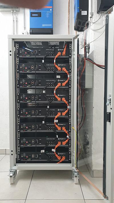
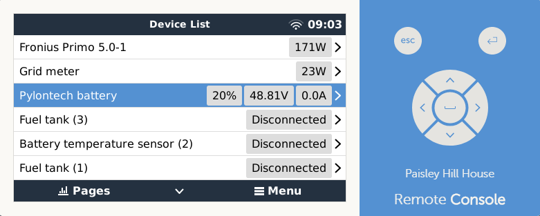
Hi I have a job with 6 pylonTech U2000 connected to a MultiPlus 48/5000/70-100 Firmware 459 and Venus GX Firmware v2.60~35. There is a grid meter, 5kW of fronius solar on the output and 5kW of solar on the input to inverter. I have a number of battery issues that could be related and was wondering if anyone had some Ideas.

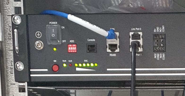
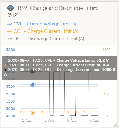
1. The GX is telling me the charge current limit is 100Amp But if change Current is 25Amps per battery this should be 150Amps. I have tried multiple times and ways to detect batteries but no luck getting the 150Amp limit. is there another way to see what has been detected by the GX?

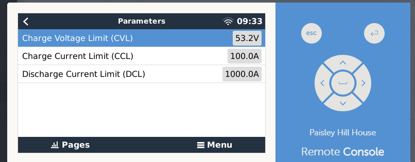
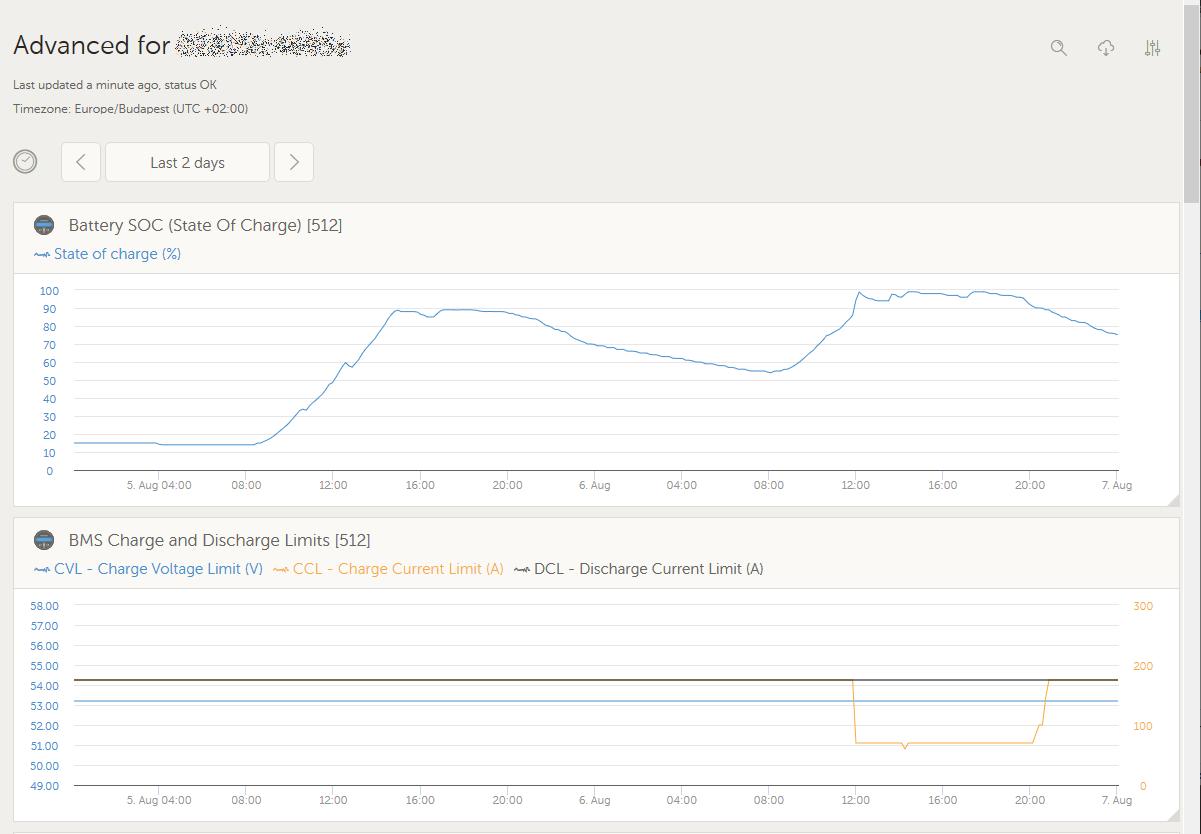
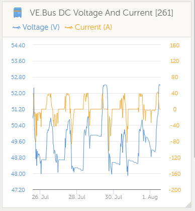
2. The batteries will not charge at more than 40Amps. Excess power is been exported insted of going into battery so battery is not fully charged some days. What could be limiting charge current?

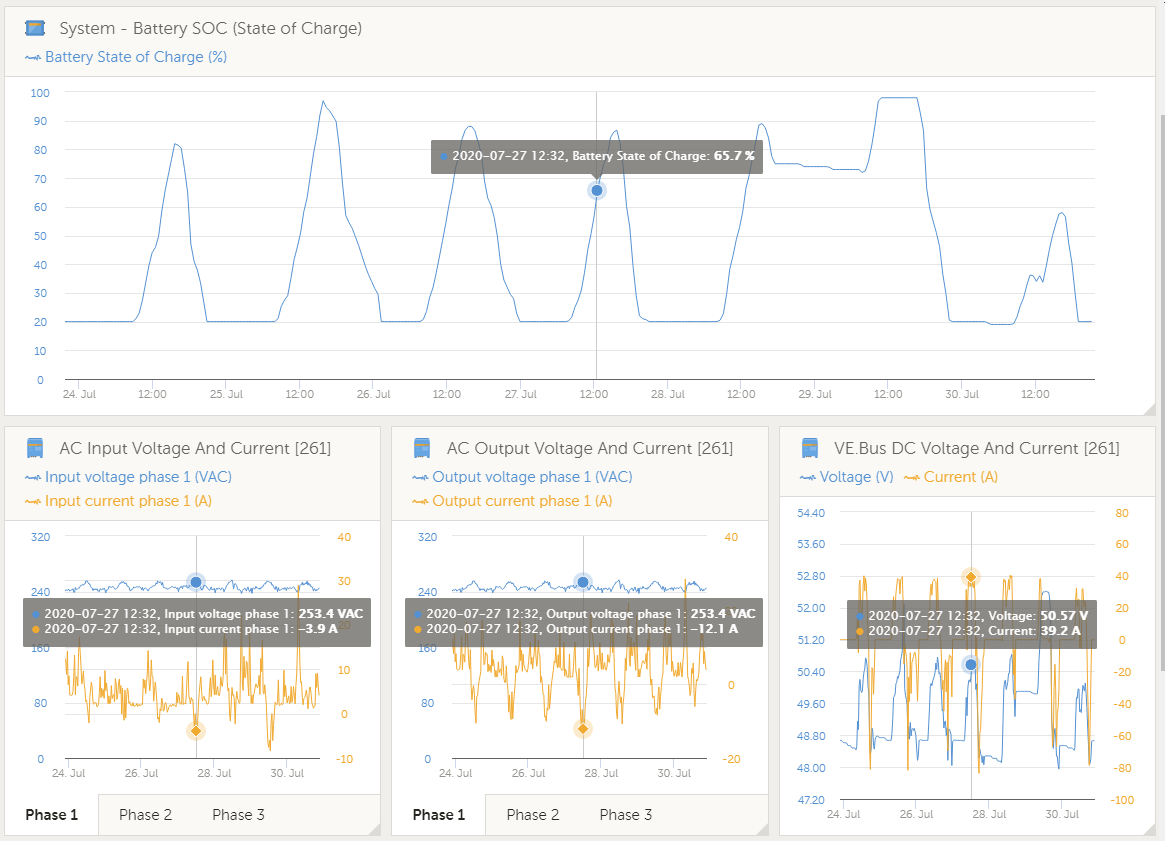
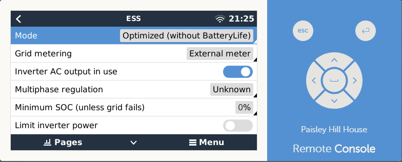
3. In the ESS I have minimum SOC Set to 0% but the VRM is showing they only discharge to 20%. What could be stopping discharge to 0%? (have tried setting at 10% and 5% but same result)

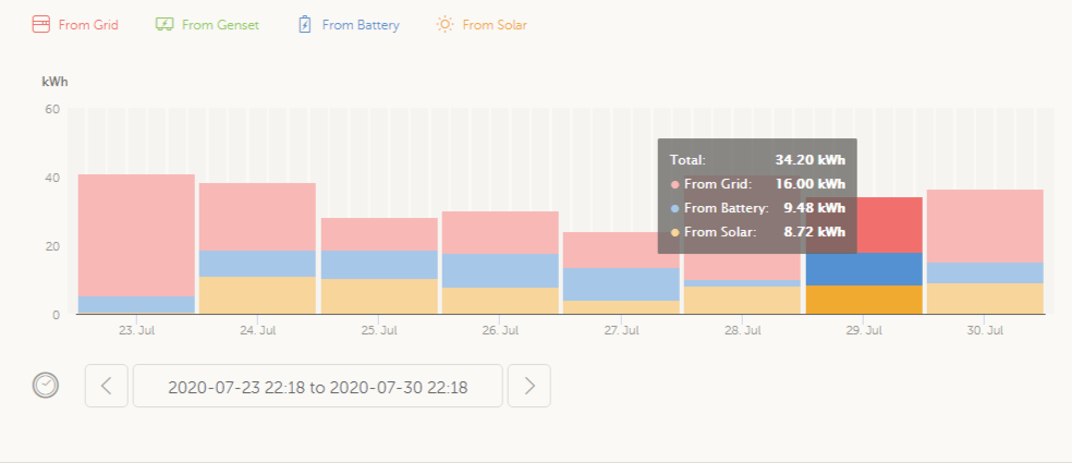
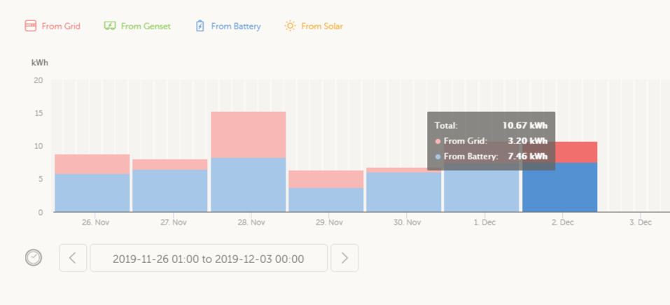
4. From a indicated 98% to %20 SOC VRM is telling me I am getting best case around 9.5kWh form the battery a day. if the usable capacity of the pylonTech U2000 is 2.2kW I should technically getting 10.5kWh to 20% SOC from 6 batteries so I'm 1kWh short, Is this normal? But alternatively if I only have 4 batteries as indicated buy the charge current limit I should only be getting 7kWh a day. so it looks like I'm doing better than 4 batteries. Is there another way to tell if all the batteries are working OK?

Thanks in advance for any tips on these points

Cheers Jon.

ESSPylontechcharge current limit
screenclip.png (26.5 KiB)
screenclip.png (32.8 KiB)
screenclip.png (136.7 KiB)
image.png (96.5 KiB)
2 comments
2 |3000

Up to 8 attachments (including images) can be used with a maximum of 190.8 MiB each and 286.6 MiB total.

the-doon avatar image the-doon commented ·

I was researching pylontech batteries on this site last week and I’m pretty sure one of the Victron team said that the settings supplied to Victron by pylontech are 98% max charge and 20% min SOC. So I’m assuming as soon as you connect the batteries and get the CANbus communicating these will be the figures you are limited to.

0 Likes 0 ·
jon-lowbank avatar image jon-lowbank the-doon commented ·

Hi Doom can't find that thread. But If that was the case are they saying you can only get 78% of the pylontech nominal Capacity of 2400kWh or 1872kWh ? The spec sheet I have says 2.2kWh "Usable Capacity".

Looking back on data when 4 batteries were installed I was regularly getting 7-8kWh to loads from batteries or 1.875 to 2kWh per battery with an indicated 20% minimum SOC. so I did get around that or better which could be expected with new batteries. So the 98% max charge and 20% min SOC limits could be correct.

I do have another off grid site (not ESS) that also recently cut out at %20 SOC. So it maybe that the Victron/pylontech U2000 capacity is intentionally limited to 1872kWh.

Even if so, now with the 6 Pylontech U2000 I am only getting 1.58kWh at best from each battery. which is a inconsistent result and indicates some other type of problem.

0 Likes 0 ·
3 Answers
dayandnight avatar image
dayandnight answered ·

Hello @Jon_Lowbank,

I run a system with 8 pylons US2000B and not being a real specialist I can only try to assist. I will try to give you based on my experience some feed back.

I am very sure, this values will be reported based on the feedback from Pylons BMS thru CAN-BUS. When there is a value of 100A your system thinks there are only 4 units. (4 x 25 A = 100A). What is very strange for me is the DCL with 1000 A which is completely wrong. This should be with 4 units as well 100A or with 6 units 150 A - but 1000 A? I would be a happy person to possess 40 pieces of Pylontech US2000B! ;-)

Did you have a look at the VRM site? Here is a screenshot from my site. Actual I run seven Pylons, one of eight is broken and away for replacement, so it show 175A (7 x 25 A) - before there was 200 A for eight batteries.

You can see for example, when SOC reaches 100% the BMS reduces the CCL from 175A to a much lower value. So there is communication from the BMS to the GX-device, which you can follow at VRM.

So the question is, is your system really connected by CAN-Bus to your Pylon stack? Wrong cable? Wrong speed? Wrong socket?

Can you remember, did you do any modification and the 1.000A was entered somehow, I can't imaging how, manually from you?

Here is a photo from my Pylon stack, perhaps you can discover something which is different to your installation

All dip switches on all devices are the same? Alle devices are online and shows the green RUN LED and the green SOC LEDs? Any device with an RED alert LED lit? All units with POWER = ON?

I know all the above question would cause to show less units! But why is 1.000 A DCL? Which leads to a fault in the communication or else where a problem.

What happens when you start the system only with fewer units, for example simply one unit? BMS should than report 25A. I can imagine if one batterie blocks or do something bad in communication that you get weird values.

If such a "bad" batterie manipulate the communication in sense of stupid behaviour you can identify this device by removing it from the stack or might be by simply switching it off, too.

I wish you success! Kind regards!

DayAndNight


vrm-pylon-01.jpg (69.1 KiB)
pylon-cabel-01.jpg (47.1 KiB)
2 |3000

Up to 8 attachments (including images) can be used with a maximum of 190.8 MiB each and 286.6 MiB total.

jon-lowbank avatar image
jon-lowbank answered ·

I will add some more history.

4 PylonTech U2000 Batteries where installed in September 2019 and two more added on 17th of March 2020

when I added the two new batteries I did have problems with the communications I tried lots of combinations but on the day what I have now is the best I could get it. (The battery status LEDs all the same and no errors) going back to 4 batteries gave expected results. I Think the cabling is OK as it worked with 4 batteries and the Discharge limits are changing on the VRM


So I'm thinking there must be a communications problem within the batteries. What I need is a way (procedure) to prove this to PylonTech for warranty.

Maybe switch one on at a time detect and check CCL and DCL in GX

Looking back on data when 4 batteries were installed I was regularly getting 7-8kWh to loads from batteries or 1.875 to 2kWh from each battery on average. Now I am only getting 1.58kWh at best from each battery meaning the customer is not getting value out of the 2 new batteries because of these problems.


image.png (86.0 KiB)
screenclip.png (29.3 KiB)
screenclip.png (33.9 KiB)
screenclip.png (102.4 KiB)
1 comment
2 |3000

Up to 8 attachments (including images) can be used with a maximum of 190.8 MiB each and 286.6 MiB total.

Did you balance all the batteries to 100% individually before installing them?

Did you update the firmware of all batteries to match at the time of installation?

0 Likes 0 ·
Guy Stewart (Victron Community Manager) avatar image
Guy Stewart (Victron Community Manager) answered ·

A common cause of an unexpected SOC minimum value is the programmed sustain voltage that is set when installing the ESS assistant in VEConfigure.

If you lower that minimum voltage threshold (which overrules the min SOC value in the GX menu), then more battery will available to you.

Please only ask one main question per community post. It is fine to have 4 or more posts about the same system when you have different questions, and makes the site much more useful when looking for answers. https://community.victronenergy.com/questions/5889/new-victron-community-guidelines.html

1 comment
2 |3000

Up to 8 attachments (including images) can be used with a maximum of 190.8 MiB each and 286.6 MiB total.

jon-lowbank avatar image jon-lowbank commented ·

HI Guy I did have the thought I would be in trouble for the multiple questions but thought they maybe related and individually they could be out of context.

But you maybe right about the Min SOC as I set the ESS assistant in VEConfigure as per instructions. Dynamic cut-off values @ 46V and Sustain voltage @ 48V

In the blow graph the voltage must momentary be hitting 46V (not shown on graph) and them sending system into Sustain Mode to hold voltage around 48 to 48.8Volts.

It is interesting though that this always relates to exactly 20% on the GX SOC chart. Can you explain this?

When on site next I will try lowing the Sustain voltage to 47V and see if makes a difference.

If you don't think this is related to the communications Issue can we move it to another topic?

0 Likes 0 ·
screenclip.png (31.3 KiB)