question

kevstone122 avatar image
kevstone122 asked

How to control Battery charge current with ESS + DC coupled feed in

Hello community, i have a very interesting Question from my side because no one can answer me this. Also not my Victron parts seller.

  • Standard ESS System with 3 or 6 Multiplus. 48-54V System!
  • A Few Victron MPPTs
  • Cerbo GX
  • Shunt

Over the DVCC there is a current Limit for Battery. If the DC coupled feed-in is OFF, then everything is working fine and you can limit the current for the Battery with the DVCC Limits.

But if the DC coupled feed-in is ON, the cerbo-gx ignore the DVCC settings accordings victron manual and also tested in reality. The MPPTs need to be always on full power, to be able to feed in.

But how can i control now the Batterie current? Also the DVCC Voltage Limit doesn't work. This was my second idea, to adjust for example 45V Limit, then the Multiplus should move the MPPT Power into the grid, but it doesn't?!

I want to prevent overcharging the Batteries, so activate some current or Voltage Limit, that the Batterie will not rise up more and more. Doesn't matter a few amperes in or out, but should be around +-5A. So the MPPT power should be used for the house + grid if the shunt shows 100% and then the multiplus should control the shunt current to 0A.

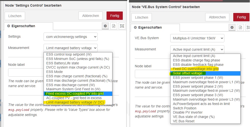
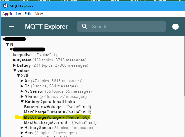
Is there any parameter to write in Node-Red to Limit the battery shunt current? Normally DVCC, but system doesn't listen to it with DC-coupled mode! Thank you a lot!

cerbo gxESSSmartShuntDVCCcharge current limit
11 comments
2 |3000

Up to 8 attachments (including images) can be used with a maximum of 190.8 MiB each and 286.6 MiB total.

Stan avatar image Stan commented ·

The easiest solution is to have enough battery to absorb all peaks of PV.

1 Like 1 ·
kevstone122 avatar image kevstone122 Stan commented ·

This is not the problem. Also not the problem in 10 years.

The Problem is, that you cannot use the same current at 30% SOC or at 95% SOC. This must be controlled. Each new smartphone has Quick charge, but the time from 0 to 50% is different to charge from 50% to 100%. All because of temperature, Physical limits. If the phone is in the sun or processor is uses and its getting hot. All these effects create dynamic limits to charge the phone well.

Also there will be the voltage higher to charge the phone that fast because also this is physic, that the voltage flow from higher potential to the lower potential. The more difference we have, the more current flows. BUT in the end it's not working with this voltage and so we need to ramp down to prevent overcharging.

One problem is coming extra at series batteries. To control also the difference voltage and be sure that all batteries are same "used".

Normally 3,45V vor each LiFePO4 battery. 3,45 x 16 = 55,2V. Try to charge them with 15kW PV. If the battery has already 53 to 54V, you will not get in the power anymore because the gap with ~1V is not enough. If you have ~2V gap it will be still charge it.
This are showing me my tests!

0 Likes 0 ·
shaneyake avatar image shaneyake kevstone122 commented ·

With LFP you can just set the charge voltage to 3.48 x 16 = 55.8V and not worry about it.

The current will start out high at low SOC but as the battery voltage gets closer to the charge voltage the current will tapper off. The mppts will then hold the bus at 55.2V and the multiplus will export the rest.

Yes, it will take 1-2hours to go from 95-100% but that is really not a problem, it is actually better for the battery to be slowly charged at the end.

Your cabling and bus bar setup should be designed to minimize any voltage difference.
Different voltages between cells will be handled by the balancers, and since there isn't a huge voltage difference between battery and charger, there won't be huge currents so the balancers can keep up.

I have designed system from 5kwh to 400kwh, with most of my systems being larger than 100kwh, we typically have over 32kw of PV. Constant voltage works and even as the battery ages, it doesn't have any problems. We have packs that are 8-9 years only still running constant voltage.

0 Likes 0 ·
kevstone122 avatar image kevstone122 shaneyake commented ·
Hello.

Sorry what is LFP? Then i can test this settings?

0 Likes 0 ·
shaneyake avatar image shaneyake kevstone122 commented ·

LFP is Lithium ferrophosphate which is the same LiFePO4 but been shortened to LFP in the industry.

0 Likes 0 ·
kevstone122 avatar image kevstone122 shaneyake commented ·
I am sorry, I was thinking some victron settings. That's why it was not clear. Sorry!


So once again.
I can just adjust two voltages in the Multiplus and two time-settings:

Why i need float and absorber at LFP, the batteries doesn't have this like lead batterie. It will also overcharge.... The timeing will be never correct in my opinion?

Absorbervoltage: ??

Floatvoltage: ??

Repeat Absorbervoltage time: ??

Intervall repeat: ??


The settings above will be same at the MPPT (Taken from ESS) plus 0,2V or something like this more, correct?


0 Likes 0 ·
Stan avatar image Stan kevstone122 commented ·
I disagree. If you have enough capacity of battery the charging current should be less than 0,5C (better 0,3C), so you are ok and it doesnt matter if SoC is 30% or 90%. Of course different chemistry has different results, but for LiFePo4 is max. 0,5C ok.
0 Likes 0 ·
shaneyake avatar image shaneyake Stan commented ·
This really depends on the cells you have and what the manufacturer recommends.

I have some LFP cells that can be charged at 1C no problem, I have others that can't be charged at more than 0.1C.

0 Likes 0 ·
kevstone122 avatar image kevstone122 Stan commented ·
Yeah this i also find out during my tests. I have now around 0,3C charging current.

But some people don't want to spend so much money and use only 1 Pack, then there musst be also a good controller to charge it very fast during winter time and a short sunshine time....This is with voltage not possible... It's to slowly and you lose a lot of energy because you push it into the grid.
With my DVCC current control you can fill them up very fast which is still healthy for the batteries. Just hold the 0,3 to 0,5C from 20 to 90%. With less voltage setting it is not possible, because voltage rise up already at 50-70%. Then it's very slowly!

0 Likes 0 ·
nickdb avatar image nickdb ♦♦ commented ·

Most of this is well documented in the DVCC section of the CERBO manual.

The limit charge voltage is for managed batteries only (ie lithium BMS), it is a temporary option for addressing cell balancing issues and will not work for unmanaged/traditional batteries.

The best you can do, is hard set limits in each MPPT, but this will affect the overall performance.


0 Likes 0 ·
kevstone122 avatar image kevstone122 nickdb ♦♦ commented ·
The voltage in MPPTs is not used if you have ESS. All voltage settings are comeing from ESS / multiPlus settings. This is an victron issue, to be not able to control the current with DC coupled aktivated. This should be no problem for the internal software to control the shunt to an current limit. It's easy to feed all energy into the grid to hold the current setpoint.
0 Likes 0 ·
16 Answers
kevstone122 avatar image
kevstone122 answered ·

Hello Matt1309,

sorry for the long answer, but i feel like you know also a lot about the batteries and so i try to explain you my system a little bit. I improved this all below the last 12 month to get every system stable. Doesn't matter if 300Ah, 600Ah, 1000Ah battery, 16S, 17S. Controller is doing his job :).

If you don't care, don't read it :D!


thanks for your answer. I like it how the people are playing with the self-made batteries and also adjustments.

Okay first because of problems with BMS, this depends how much PV Power you have or inverters compared to your batteries.

I have some friends and different battery setup and if the friends use it out of limit, then without controlling from BMS it's game over. For example 3 Multiplus 5000VA on 16S Battery system with 300Ah. 3x70A = 210A discharge current. The Battery will do that, but not until 20%.... For each LiFePO4 cell is the limit around 80 to 130A i find out to use it stable. If there is no controller, multiplus will switch off always with voltage minimum because BMS switched off already! (At 5,6 systems tested).

Important is also that i am not talking about only the first 5 to 10 years. The problems will come in the future with the time and the system will be more and more unstable because of older batteries. Of course any cell starts to get problem and then the "global" voltage from the full package is not relevant.

I have connected the BMS with serial adapter to read in all data and take it with MQTT into Node-Red from cerbo-gx. So every Voltage is showing up. I control the current with 4 different controller. Voltage difference, Voltage Max, Temperature, SOC.


Without NodeRed for my opinion it's not working with high power. I am using 6 Multiplus with 25kW PV. Current control is from 0 to 480A. On sunny days this will jump like hell and if you have here time settings for voltage it will not work. The current is no problem for the pack, but if you reach around 90-95% the problem starts. You cannot charge with 480A anymore at 95% SOC.

Maybe in 10 years it will be more and more problem and so the controller need to be a dynamic limit.
Same for discharging. Instead of Voltage Max i use Voltage Min. Rest is same.


Yes good to compare with each cell. No i am using almost the same value like you.

Absorber and float 3,6V. Because i don't want to use this timing from victron which i cannot control, don't know any parameter and cannot react for this. For example the re-bulk time, when it starts to do this. If the Battery has 95%, i never want to re-bulk. Batteries will be overcharged. So cloud is comeing, system rise up after this the voltage, but no need to do it, okay that's my opinion....I don't get it runable and stable with this and i am sure in 10 years it will also not work!


We need also separate house and camping/boat and so on. In House if it will switch off complete, it's more problem then on the boat! I am talking about house regulation!


So the important settings are the controller like Linear-function, nothing special:

DVCC will be limited by:

DifferenceVoltage: 70mV to 90mV. Until 70mV 100%, at 90mV 0%

MaxVoltage: 3,45V to 3,49V. Until 3,45 100%, at 3,49V 0%

Temperature: 40°C to 50°C. Until 40°C 100%, at 50°C 0%

SOC: 90% to 100% with minimum output to charge full. Until 90%SOC 100%, at 100%SOC still 30%

Between all values are linear. So 45°C means 50%.

In NodeRed i take the Minimum value of these 4 controller outputs. So the controller with the smallest percent value will be taken and multiply with the maximum current settings which is in my case 480A.

If you have an difference Voltage problem and controller says 50%, but Endvoltage is reached and you have only 10% at this controller, then DVCC current will be 10% of 480A. So Setpoint is 48A. All values are added to ramping function and it ramp up and down. Immediately the MPPTs ramp down.

During the ramping down because of the DVCC current limit, the controller will maybe increase the output because Maximum Cell Voltage also goes down. So it will rise up to for example 20% --> 96A. And so you can see, how the batteries get COMPLETE charged with EACH CELL. Until all controllers show 0%, then there are all cells at 3,49V.


Limits in BMS: 3,55V Max, 150mV Difference, 2,8V Minimum (Victron 2,9V), Charge and discharge current MAX 490A. So i try to control all within the range of NodeRed. In worst case the BMS reacts.
Also if i change the Endvoltage to 3,52 instead of 3,49 i can see immediately that in the end the difference Voltage will rise up and still the other controller reduces the current to be stable.
So in my case i can charge my batteries complete from 0 to 100% with the mode "keep batteries charges" and everything has no alarm. Doesn't matter from which SOC Point i start. SOC level is comeing from Victron Shunt just to know because here we have the peukert-exponent to adjust. BMS doesn't have ;)


Important is also, that the SOC value is not always correct and so not trust-able after several years because of reducing Ah from year to year. To charge only with SOC level like absorber and float settings may not work in 10 years. Also during winter time, if you never reach 100% of batteries, the SOC limit will drift and just show something. You need to charge manual to 100% after 1 month to be synchronize again.


I hope it was interesting and thanks for help from everyone here!

2 |3000

Up to 8 attachments (including images) can be used with a maximum of 190.8 MiB each and 286.6 MiB total.

matt1309 avatar image
matt1309 answered ·

Hi @kevstone122 ,

If you aren't using ESS i believe the charge limits can be set within the MPPTs via VictronConnect app

However given you are using ESS i believe the MPPTs get their charging settings from Multiplus/VEConfigure. The settings you're looking for are therefore likely updated using VeConfigre (absorption voltage will then be the max the battery will be charged to).


If there's excess power once in absorption/float stage it will be exported to the grid if it's connected. If it's not connected the MPPT with ramp down their output just to cover the loads as to not overcharge the battery.


2 comments
2 |3000

Up to 8 attachments (including images) can be used with a maximum of 190.8 MiB each and 286.6 MiB total.

nickdb avatar image nickdb ♦♦ commented ·
First, limits should always be set on the chargers regardless of the config of having a GX and/or a managed battery.

Even with ESS, these limits are followed, if they are set lower than what is requested externally.


0 Likes 0 ·
kevstone122 avatar image kevstone122 nickdb ♦♦ commented ·

Okay that's correct. But i am talking about an dynamic limit. So the current will be limited automatically from BMS from 400A down until 0A with the "CellMaxVoltage", "DifferenceVoltage" and Temperature ratings.
So if something is unstable from the battery, the victron system reduces charging current. If i don't do it like this, then BMS will switch off anyway. So this make no sense to wait until this limits. If you know BMS limits, you can handle before these limits and ramp down.
This is the professional charging like in a smartphone. Quick charge is not working over time and voltage settings. There is a current controller to control the current from 100% to 0% with the Battery Temperature, SOC cell voltage. The current can be only reduced, if the voltage goes down. So if DVCC is limited to 200A instead of 400A, automatically the MPPTs ramp down because they get less voltage setpoint.

But with DC coupled it is not working. :(

You know what i mean?

0 Likes 0 ·
kevstone122 avatar image
kevstone122 answered ·

Hello Matt1309 and thanks for your answer.

I am using ESS of course :)

To charge the LiFePO4/lead Batteries, you need to have a higher voltage for charging to push more energy inside in a short time. Current flows from the higher potential to the lower potential.
So my charging Voltage is 1 or 2 Volts higher then the End-Voltage.
Over Node-Red i can control the DVCC-current limit according the BMS. So if the BMS tells me, some cell has the maximum voltage, then the DVCC current limit will be reduced. So with this DVCC setting i can complete charge my batteries perfect at the moment in a short time.


But if DC-coupled is switched on to be also able to feed into the grid, it will not work anymore.
I cannot limit the current for the battery to charge them perfect.

The Victron idea with absorber and float voltages is for LiFePO4 Batteries not really useable i tested. Because you never no the point, to switch from absorber to float. Also the SOC level is just calculated and not to exactly. With the old "lead battery" it was no problem to have higher voltage a short time, but at lithium with BMS it doesn't work. BMS will always switch off to fast because cell voltage drift. Also no "time" settings are usefull here. With re-absorber Voltage X Minutes... This you cannot use for some time because the BMS is the master and not some time settings. So Limits are comeing from BMS to prevent overcharging. This are my tests on cloudy days and startet several re-bulk times until BMS switch off and the house shut down... Not useable.

How does it work with and original Victron BMS. If the BMS "says" stop charging, then the current to the shunt will be controlled to 0 i guess. So Multiplus push the energy into the grid i think...
And this parameter i want to set also in NodeRed.

If there is not Grid, then of course we need to ramp down MPPTs like it works now without DC-coupled activated!

Thanks!

4 comments
2 |3000

Up to 8 attachments (including images) can be used with a maximum of 190.8 MiB each and 286.6 MiB total.

shaneyake avatar image shaneyake commented ·

DC-coupled, uses a system called Overvoltage feed-in where the mppt tries to raise the votage above the setpoint and the inverter then exports enough to keep the voltage lower.

You can change the Overvoltage valves from NodeRed, I am not sure if you can set negtive valves for Overvoltage but you could lower the charge voltage in the inverter and then increase the Overvoltage limits to get to your desired voltage and if BMS wants less then you can set Overvoltage limit to 0. Overvoltage limit is an offset, so charge_voltage+Overvoltage will be MPPT output.

1 Like 1 ·
kevstone122 avatar image kevstone122 shaneyake commented ·

Hello Shaneyake!

Wow thanks for this information, this nobody could tell me right now.

I understand your idea and like it. I try already to find it in Node-Red. Two screen shots below with 4 different options for me which are possible. What do you think is correct?

node-red-ess.jpg


I am waiting for your feedback and then i can try with negative values also.

This will be perfect!

I hope this is working!


0 Likes 0 ·
node-red-ess.jpg (183.3 KiB)
matt1309 avatar image matt1309 commented ·

"Current flows from the higher potential to the lower potential.
So my charging Voltage is 1 or 2 Volts higher then the End-Voltage"

I would always have done this by setting absorption voltage of 2v above float rather than going NodeRed route.

I've got a slightly different setup, I've had no issues using absorption/float setup with LiFePO4, but saying that i opted to not use BMS communication for managing charging rates, so I've not had the BMS issues you refer to.

I instead opted for a smart shunt and just use absorption time and tail current to determine how long to stay in absorption phase before moving to float stage.

Only disadvantage I have is I cannot see individual cell voltages via the Victron system (i use a different app for BMS monitoring to see that). My logic is i shouldnt need this data often if I have a decent battery/relatively well balanced cells (and a BMS with built in balancer)


Personally I wouldn't be a fan of solving your problem with NodeRed to me it just feels like it adds another potential point of failure and complicates the system (of course that's personal preference)

My proposed solution would be reducing max voltage in victron system. That way BMS wont interfere with overcharging and you can use the absorption/float method without any hassle. (alternatively increase max voltage in BMS if it's too low and if you can edit BMS settings)

For example the below voltages are what i use (I'll do the example per cell as I'm unsure the size of your pack so multiple the below numbers by the number of cells in your pack)

In Victron system.

Float 3.4v

Absorption 3.5v

Tail current (whatever works for you, current i use 4%).

And similarly play around with absorption timers.


My BMS settings. Max per cell voltage 3.63v (I know that's far lower than what most folk use but i want to maximise longevity of the cells)

Your BMS will likely have much higher overcharging settings ie 3.65v or even higher. However as you're aware the amount of capacity you're losing out on between 3.5v and 3.65 is minimal for LiFePO4 (steep part of the curve) I imagine less that 2%. Also puts far less stress on the batteries using those voltages in my opinion.


0 Likes 0 ·
kevstone122 avatar image kevstone122 matt1309 commented ·
Because of the letters limit in the answer field, i move it down to the global answer!
0 Likes 0 ·
kevstone122 avatar image
kevstone122 answered ·

I think i will test my own Grid-Feed-in with NodeRed.
With this i can use higher voltage for perfect charge and still my own current controller for the next 20 years!

2 |3000

Up to 8 attachments (including images) can be used with a maximum of 190.8 MiB each and 286.6 MiB total.

wolferl avatar image
wolferl answered ·

hi Keystone122

i picked up your approach and fed it into a virtual battery, which combines my two self made batteries (https://github.com/Louisvdw/dbus-serialbattery)

The driver of the virtual battery: https://github.com/arrow1800/Victron-VirtualBattery


I calculate the CCL in node red and feed it into the virtual battery, which is then used by VensuOS to control the system.


As the CCL is not obeyed, if your MPPT are set to feed in excessive energy, I needed an additional approach: Based on a certain max cell voltage I control the charging voltage as well in a linear way. This helped a lot as well when it came to spiking of the cells at higher SOC...

So far, this works perfect.

2 |3000

Up to 8 attachments (including images) can be used with a maximum of 190.8 MiB each and 286.6 MiB total.

kevstone122 avatar image
kevstone122 answered ·

Hello wolferl,

sorry for the stupid question. What do you mean with CCL?

Okay i checked the github links and great what you prepare here...

In my case there was already an Python driver for the ChargeryBMS on Github and this creates my "Battery Display", same like yours with "virtualBattery".


This was the first important stuff to catch the data into the cerbo!.

All rest we can do in Node-Red and have no limits.


The charging voltage is one way or to use the current limit like we do it....
Problem is, both is not use able, if you feed into the grid also because then MPPTs run always at the maximum. So now i try to create an grid feed in controller....If system says 50A only into the battery because cell max voltage, then all the other energy which is comeing from MPPTs minus the house-used energy must feed into the grid. So current should be stable at 50A....

2 |3000

Up to 8 attachments (including images) can be used with a maximum of 190.8 MiB each and 286.6 MiB total.

wolferl avatar image
wolferl answered ·

Hi keystone

CCL means ChargeCurrentLimit

You‘re right when it comes to managing the current. As long as you feed in the excess, the current of the DC coupled PV is not adjustable. There is where the voltage comes into play in my system. Eeven if you cannot manage the current, the voltage in an ESS system can be adjusted, also if you feed in the excess PV.

By lowering the voltage to a target voltage, actual current gets lower from itself. As I have a mixed system (PV charger and PV inverter) this works very well. The multis limit the current coming from the PV inverter to the batteries and feed in the excess and by lowering the charge voltage from the MPPTs the batteries do not consume the full current of them. Excess is fed in.

What you don‘t have in such a system is an exact manageable current. From my perspective I do‘nt need that as the last 5-10% are better managed by voltage. In that case the current reduces automatically as the battery is not able to absorbe more energy. It is also possible via Node Red to increase charging voltage in steps depending on cell voltage if you want to go even slower to avoid cells spiking…

2 |3000

Up to 8 attachments (including images) can be used with a maximum of 190.8 MiB each and 286.6 MiB total.

kevstone122 avatar image
kevstone122 answered ·

Hello Wolferl,


Thanks for the feedback and CCL :)!

I understand the idea with the voltage, but i try to use the DVCC Voltage limit settings. For example if i adjust only 30V (have 48V System) it should start to feed into the grid, but it doesn't.

I just found the 0,1 or 1,0V adjustment wich is used for the offset for the MPPTs, but if you use "manual charge" with the multi plus, this voltage will be not used i think. So then i have not so much charging power if i adjust 3,45*16cells = 55,2. Because of the High PV Power it starts already really early to feed into grid which is not good. So i need some charge voltage around 57,6V in the multiplus.But then i cannot set the DVCC Limit lower....or in my case it does not work...
Is this the problem? Which voltage do you use in multiplus and which offset for MPPTs?


Thank you!

2 |3000

Up to 8 attachments (including images) can be used with a maximum of 190.8 MiB each and 286.6 MiB total.

wolferl avatar image
wolferl answered ·

Hi

I don't switch on DVCC voltage limit or use that switch in any way.

I use "N/XXX/battery/15/Info/MaxChargeVoltage"

This sets the CVL (charge voltage limit) of the battery.

If I set this lower than the actual battery voltage, the battery is discharged, if I set it highter, the battery is charged. The MPPT considers this value, so even if I feed in excess, it's done with a lower DC voltage to consider the battery. Of course, you cannot control the current going into the battery directly, but indirect you do.

CVL nearer the actual battery voltage ==> lower current into the battery

In my system CVL is set dynamically in Node Red, if I see a cell spiking I lower CVL, if everything is in balance I raise it to a certain max which reflects my target voltage of the battery.

2 |3000

Up to 8 attachments (including images) can be used with a maximum of 190.8 MiB each and 286.6 MiB total.

kevstone122 avatar image
kevstone122 answered ·

Hi, this sounds really what i need. This i need but i didn't find.I have only this!

But if i write this parameter nothing happen!
You have any idea?
"/15/Info/MaxChargeVoltage" doesn't exist! Also not with another number... No Info tab or name with MaxChargeVoltage!
1678777523099.png


1678777523099.png (41.6 KiB)
2 |3000

Up to 8 attachments (including images) can be used with a maximum of 190.8 MiB each and 286.6 MiB total.

wolferl avatar image
wolferl answered ·

Hi

The path is different to what you have in your pic. it is under the battery branch, 15 is the VRM instance (with the virtual battery you can choose this by yourself), you could have a different VRM instance...


2 |3000

Up to 8 attachments (including images) can be used with a maximum of 190.8 MiB each and 286.6 MiB total.

kevstone122 avatar image
kevstone122 answered ·

Hello,

because i didn't have it in the battery tab, i show you the other position. Here is the Battery tab.
Maybe i need for this the "virtual Battery" to be able to write the limits?

1678823151277.png


1678823151277.png (43.4 KiB)
1 comment
2 |3000

Up to 8 attachments (including images) can be used with a maximum of 190.8 MiB each and 286.6 MiB total.

wolferl avatar image wolferl commented ·

That's odd

I use two batteries with Daly BMS and the serial battery driver (https://github.com/Louisvdw/dbus-serialbattery) to get the data into VenusOS.

This driver already creates the item for me for the real batteries. In my case I don't use them as I calculate the values by myself in NodeRed.

The virtual battery driver creates the items as well, and I fill them from Node red.

Have a look at github and see the file virtualbattery.py. In this file the items published to the dbus are defined. The three values CCL, CVL and DCL are defined in "# Create control paths" and the corresponding items to fill the paths with values further down the script...


0 Likes 0 ·
kevstone122 avatar image
kevstone122 answered ·

i think i got it with your virtual battery github articel... This looks like what i need. Just to catch data from Modbus or MQTT, feed it with node Red to the right positions and the systems thinks there is a real Victron BMS.
WOW!!!! GREAT!

2 |3000

Up to 8 attachments (including images) can be used with a maximum of 190.8 MiB each and 286.6 MiB total.

derrick thomas avatar image
derrick thomas answered ·

@Wolferl I am trying to install this virtual battery setup you mention but I am Linux illiterate, stuck in the windows world. The instructions on the GitHub say to create the directory which I have done but I can't for the life of me figure out how to transfer the files onto Venus os using ssh. Google searches only further confuse me. Could you possibly help me out with the commands needed to transfer the necessary files from the GitHub? I can stumble through and figure out the rest but I just can't figure out how to put the files in the right place.


Edit to add:

So I finally did figure out how to put the files in the proper location and completed the install according to the instructions, rebooted the cerbo, but I don't have the virtual battery in devices list. Yes I did add the flow to node red. I dunno where to go from here?

2 |3000

Up to 8 attachments (including images) can be used with a maximum of 190.8 MiB each and 286.6 MiB total.

wolferl avatar image
wolferl answered ·

Hi Derrik

did you start the driver?

you need to do all steps below to make sure the driver starts automatically

  • create /data/dbus-virtual-battery directory
  • copy files to this folder
  • set chmod 744 for ./service/run and ./restart
  • add this line to the file /data/rc.local : ln -s /data/dbus-virtual-battery/service /service/dbus-virtual-battery


2 comments
2 |3000

Up to 8 attachments (including images) can be used with a maximum of 190.8 MiB each and 286.6 MiB total.

derrick thomas avatar image derrick thomas commented ·
Yes I did all those steps. The third step says chmod 744 for ./service/run and ./restart I assume that is to mean /data/dbus-virtual-battery/service/run and /data/dbus-virtual-battery/service/restart

There was no rc.local so I had to create it and placed it in /data (I used command ls -a and there was no rc.local, only .rc with no file extension)

I then reboot the cerbo

Do I need to set chmod for rc.local?


0 Likes 0 ·
kevstone122 avatar image kevstone122 derrick thomas commented ·
Thank you for trying this. Looks interesting.

I will try also this weekend to install the virtual battery. You found something already with rc.local?

Thank you!

0 Likes 0 ·
wolferl avatar image
wolferl answered ·

I‘m not quite sure about rc.loval. Unix is new for me as well.
please contact the author of the driver via github. He should know…

2 |3000

Up to 8 attachments (including images) can be used with a maximum of 190.8 MiB each and 286.6 MiB total.