question

testor90 avatar image
testor90 asked

Grid feeding Problem

Hi to everybody willing to help me!

I have a Problem:

My setup:
Multiplus II
two Chargecontrollers connectetd VE Direct to a
Cerbo GX
EM24 Meter.

When I switch on the Grid power and the Multiplus starts feeding into the Grid, everything breaks down.
The Energy is flowing in every direction, back and forth from the battery and the MPII is jumping Power up and down. (If I am only drawing power from the grid everything is fine)


Also the LEDs on the chargecontrollers are blinking and it is switchin nonstop between Bulk and float mode.

If I disconnect one chargecontroller from the CerboGx everything is suddenly fine!
(Although the chargecontroller ist still delivering power and it is fed to the grid)


Where should I start looking? Everythink is updated and works great if
A) The grid is connected and the feed grid is disabeld
B) VE Direct cabel is not connected to the larger Chargecontroller.

Thank you!

cerbo gxbattery charginggrid
2 comments
2 |3000

Up to 8 attachments (including images) can be used with a maximum of 190.8 MiB each and 286.6 MiB total.

Alexandra avatar image Alexandra ♦ commented ·
@TestOr90

Check how the em24 is setup.

If you take that out the system, does it work ok?

0 Likes 0 ·
shaneyake avatar image shaneyake commented ·
What is your inverter input current limit set to? If it is too low with ESS running we get very random behavior.
0 Likes 0 ·
5 Answers
testor90 avatar image
testor90 answered ·

But if i take out the em24 how do i feed into the grid without a smartmeter?

Thx

5 comments
2 |3000

Up to 8 attachments (including images) can be used with a maximum of 190.8 MiB each and 286.6 MiB total.

marekp avatar image marekp commented ·

@TestOr90

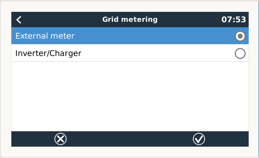
screen-shot-2022-06-27-at-75341-am.png

Assuming that you have ESS assistant loaded.

At the moment you have "External meter" (EM24) selected In GX setup. Device list>Settings>ESS>Grid metering>

Switch to "Inverter/Charger".

1 Like 1 ·
testor90 avatar image testor90 marekp commented ·
Thank you very much,


So i do not need the Smart meter at all for my Installation?!

What if i have two Phase system with two MPII?
Do i need it then?

Thank you!


0 Likes 0 ·
marekp avatar image marekp testor90 commented ·

@TestOr90

If you do not have a Power Meter on the grid connection, your system will not be aware of any loads or PV production between a grid connection and AC-in of MP-II. You will not be able to properly control the back feeding the grid.

I have 3-phase system and for short time run it without EM24 on the grid connection.

1 Like 1 ·
testor90 avatar image testor90 marekp commented ·
Thank you!


I have no other AC Sources/Consumers between my MPII and the Grid meter.
So what you are telling me is basicaly that i can return the EM24 and it is not needed for this system saving me 250 € on the installation cost.

That is some good news :)


0 Likes 0 ·
marekp avatar image marekp testor90 commented ·
@TestOr90

First make sure that you do not have faulty 3.5mm external CT jack.

That fault makes the internal CT disconnected and system does not know the AC-in current.

1 Like 1 ·
marekp avatar image
marekp answered ·

@TestOr90

Recently there was many of problems reported here related to the 3.5mm external CT jack.

When this jack develops a problem system starts behaving like in your description.

https://community.victronenergy.com/questions/136049/critical-load-shows-high-values-how-can-i-check-th.html

3 comments
2 |3000

Up to 8 attachments (including images) can be used with a maximum of 190.8 MiB each and 286.6 MiB total.

testor90 avatar image testor90 commented ·
Thank you for the response


Well I must admit i am not using any external Current Transformator at all.
Would I need to place it on the DC side of the Batteries?

It is only rated 100 Amps, but my system sometimes pulls up to 120 amps if all aircons are running (starting) (2x5000 MPII and some "change")

Should I buy one of these? Also my DC Cabels are quite ... oversized ... 95 mm2 since i got them from the scrapper for just the copperprice.


Thx


0 Likes 0 ·
marekp avatar image marekp testor90 commented ·

@TestOr90

This external CT transformer is for AC-in line not DC.

Each MP-II has an internal CT transformer but sometimes the fault in 3.5mm jack disconnects that internal CT.

If you want more accurately measure the DC current on your battery, you need to install SmartShunt or BMV.

0 Likes 0 ·
testor90 avatar image testor90 marekp commented ·
Thank you for the answer.


I disconnected the connection to my EM24 Meter and CerboGx.
Now I am using only the build in meter of the MPII.

Sun is out and soon the batteries are full and we will see if this changes anything or the System falls into chaos once again. :)

The problem is that I cannot raise the feedin limit to to grid more than 1500 W right now.

We will see what happens.

Also it is interesting that the MPII build in Meter is showing on avarage 20, 30 Watts less feed in than the EM24 on its display.


0 Likes 0 ·
testor90 avatar image
testor90 answered ·

Well the problem still persists.

Is it because of my Grid feed in limit? If it is reached the system goes crazy.
Chargind and dischargin my Battery. Dropping the pv input to zero.
Also the Grid feed in is jumping between diffrent values, sometimes 800 watts up and down.

I dont understand it. What would be next?

23 comments
2 |3000

Up to 8 attachments (including images) can be used with a maximum of 190.8 MiB each and 286.6 MiB total.

marekp avatar image marekp commented ·
@TestOr90

Did you try that 3.5mm jack trick?

Do you have DVCC enabled?

0 Likes 0 ·
testor90 avatar image testor90 marekp commented ·
What would be the 3,5 mm jack trick?

I dont have the CT dongel.

No i dont have dvcc enabled. I have the victron lynx smart shunt and a dumb daly bms system. there is no communication betweet the daly bms and victron.


0 Likes 0 ·
marekp avatar image marekp testor90 commented ·

@TestOr90

Maybe you should read this document.

https://www.victronenergy.com/media/pg/CCGX/en/dvcc---distributed-voltage-and-current-control.html

The "jack trick" is described in the link I posted.

You just plug and unplug many times the 3.5mm connector into the CT socket to clean the contacts.

0 Likes 0 ·
testor90 avatar image testor90 marekp commented ·

Thank you very much i read everything.


Can you mby pls help me understand this paragraph:

"A fixed solar offset of 0.4V is used instead of a variable 2V. (values for 48V systems, divide by 4 for 12V). Note that this solar offset is only applied when ESS-mode is set to Optimized in combination with the Feed-in excess solar charger power-setting enabled, or when ESS-mode is set to Keep batteries charged. "

Where do I set it? with all of my solar chargers?

Thx


0 Likes 0 ·
marekp avatar image marekp testor90 commented ·

@TestOr90

I thing it is this.

Re-bulk voltage offset

Set the voltage offset that will be used over the float voltage setting that will determine the threshold that the charge cycle will restart.
E.g.: For a Re-bulk voltage offset off 0.1V and a float voltage setting of 13.8 V, the voltage threshold that will be use to restart the charge cycle will be 13.7 V. In other words, if the battery voltage drops below 13.7 V for one minute, the charge cycle will restart.

https://www.victronenergy.com/media/pg/VictronConnect_-_MPPT_Solar_Charge_Controllers/en/settings.html

1 Like 1 ·
testor90 avatar image testor90 marekp commented ·
Yes i also believe that we are onto something.


So i have the 48V system. So as per instruction I must set the offset voltage fixed and 0,4 Volts. But still where do I set it?
On all devices? only the chargecontrollers?

(lifepo4)
so my float voltage on the chargecontrollers is

absorbtion: 56.4

float 54.0

rebulk offset 0.4 Volts


Hmmm this sounds right? thouse are the settings used until now with the error


0 Likes 0 ·
marekp avatar image marekp testor90 commented ·
@TestOr90

Is your Daily BMS perfoeming balancing of the sells?

If yes what is the balancing voltage?

Ir should be sligly below absorption voltage.

Why you are not using DVCC?

0 Likes 0 ·
testor90 avatar image testor90 marekp commented ·

Yes it is balancing. It was set to balance at 3,2 V // 51 V total

Mby i should turn balancing off and try again?

I already enabled DVCC. Or what exactly do you mean?
Why I dont have a communication with my bms?

Thx for your help!

0 Likes 0 ·
marekp avatar image marekp testor90 commented ·

@TestOr90

In one of the previous responses you stated that you do not have DVCC enabled. This is why I asked why not.

If you have it enable what are the settings?

If your absorption voltage is 56.4V your balancing voltage should be ca 56V. (3.5V per cell)

0 Likes 0 ·
testor90 avatar image testor90 marekp commented ·
Thank you, yes it is enabled now.

But the problem is still here.

Mby i should disable the balancing and test it again? just to rule out this as a possibilit.

thx,


0 Likes 0 ·
marekp avatar image marekp testor90 commented ·
@TestOr90

If DVCC is on, can you show the settings on DVCC page?

Balancing should not matter.

I only warn you that the way it is set up now is wrong.

If you have Float set at 54V and balancing at 51V, BMS is constantly discharging cells in your battery when it is fully charged. So it never stays fully charge even if you are not drawing any power from it.

BMS will always discharge your battery down to 51V.

0 Likes 0 ·
testor90 avatar image testor90 marekp commented ·

ok thank you for this hint, will change the bms settings.


My DVCC
Limit Charge current On

Maximum charge current 190A

Limit managed battery charge voltage ON
Maimum charge voltage 56
svs shared voltage sense on
sts shared temperature sense on
Temperature sensor automatic
used sensor ---
SCS shared current sense ON
SCS status disabled (external control)


Hope this helps.


0 Likes 0 ·
Show more comments
testor90 avatar image
testor90 answered ·

Also I noticed that the chargecontrollers are jumping nonstop between bulk and absorbtion, the battery is charged and discharged nonstop.

2 |3000

Up to 8 attachments (including images) can be used with a maximum of 190.8 MiB each and 286.6 MiB total.

lifeingalicia avatar image
lifeingalicia answered ·

There is quite some discusion about multiple MPPT

check search "multipls MPPT"

Are yours on the latest firmware? and which bats are u using (BMS)?

3 comments
2 |3000

Up to 8 attachments (including images) can be used with a maximum of 190.8 MiB each and 286.6 MiB total.

testor90 avatar image testor90 commented ·
Thank you I will ckeck this.


Yes everything is up to date.


0 Likes 0 ·
testor90 avatar image testor90 commented ·
I'm using a daly bms, 200 amps and there are no error codes or problems with it.


everything works finde until the PV input exceeds the limitation for the grid feed in and the battery is full.


0 Likes 0 ·
lifeingalicia avatar image lifeingalicia testor90 commented ·
Have you checked all MPPT settings? Grid feed limited battery full where does the extra go.... or how is it limited?

Sorry not a specialist on MPPT

0 Likes 0 ·