question

ET avatar image
ET asked

3 phase system with 2 multiplus II in parallel on each phase

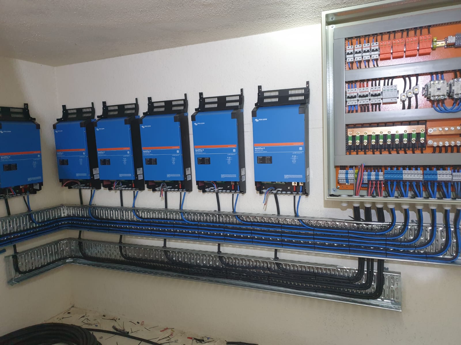
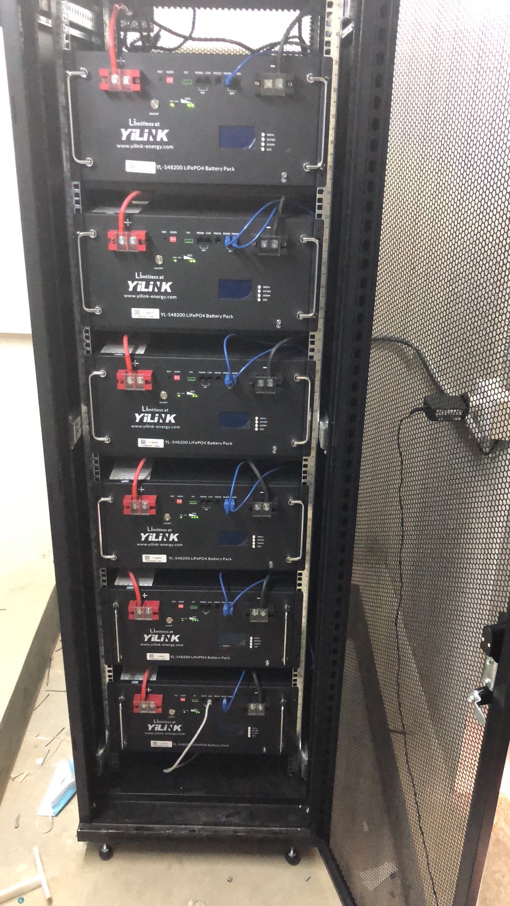
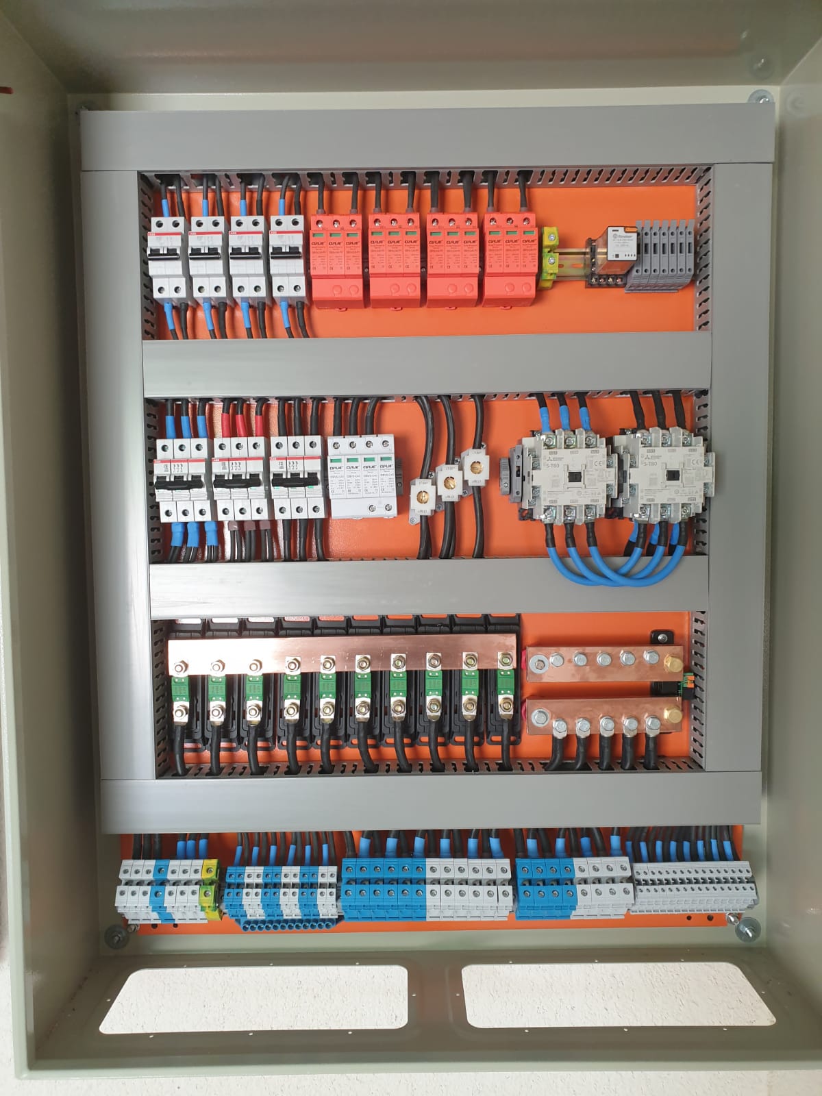
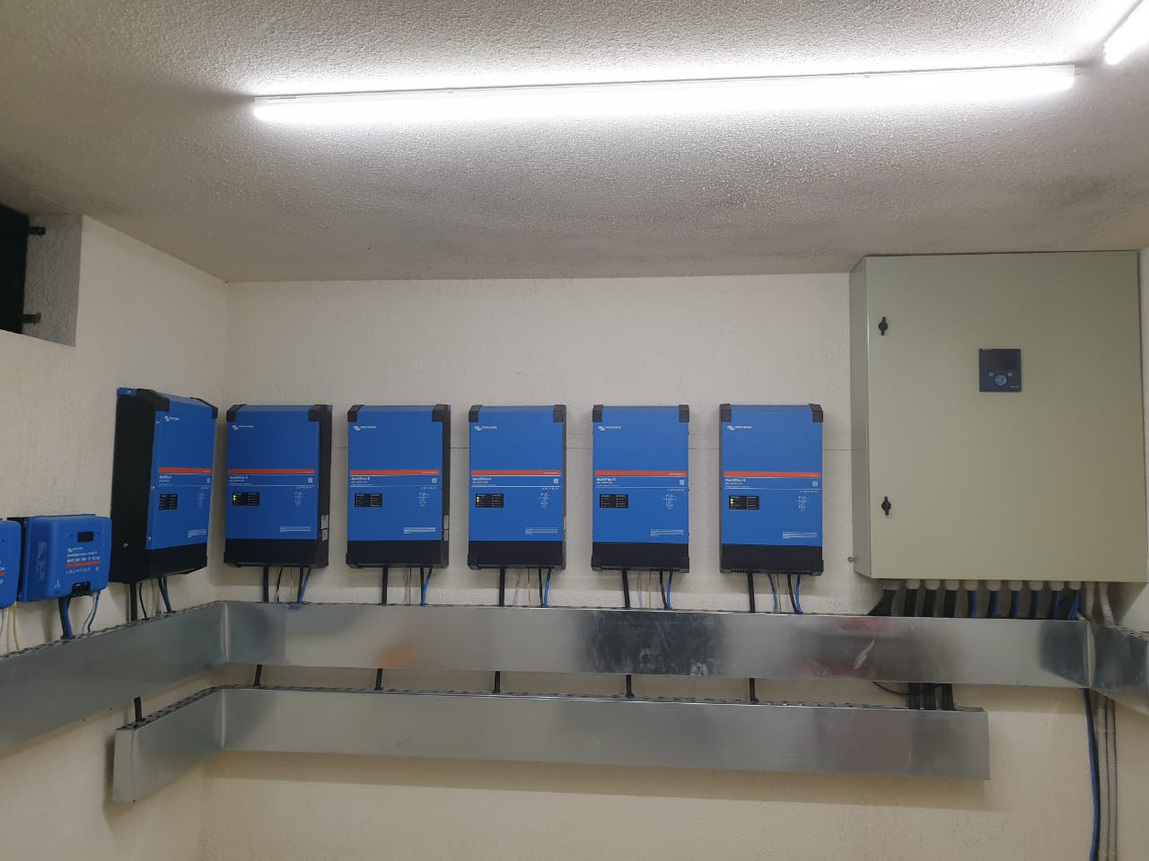
I've installed 6 multiplus II 48/5000/70-50 (2 on each phase) with 6 pylontech batteries 48V 200Ah each + 4 MPPT smartsolar 250/100 VE.CAN + cerbo GX . The system is working fine when AC input is available. The system shut down with err17 ( phase master missing ) when the grid is off and pass to inverting mode. It doesn’t happen when the generator Is off (the generator is current by the relay inside the cerbo). I’ve changed all the communication cables between the inverter and cerbo and still the same issue.

Please Help!

VEConfigure 3error3 phasemultiplus in parallel
2 |3000

Up to 8 attachments (including images) can be used with a maximum of 190.8 MiB each and 286.6 MiB total.

7 Answers
Matthias Lange - DE avatar image
Matthias Lange - DE answered ·

This seems to be a strange system.

Are they all configured to work together as a 3 phase/parallel system?

Normally all units of a system have to be connected to the same battery bank.

https://www.victronenergy.com/live/ve.bus:manual_parallel_and_three_phase_systems#dc_and_ac_wiring

Also only one GX device is needed, so you payed around 1800€ for GX devices you don't need.

7 comments
2 |3000

Up to 8 attachments (including images) can be used with a maximum of 190.8 MiB each and 286.6 MiB total.

ET avatar image ET commented ·
Sir do you have a logical answer? The design is good since I need 10kW on each phase so its not about using one or 2 since as per victron i can install up to 6 units per phase and here im installing two per phase. Please I need logical answers about the error and not about the design.
0 Likes 0 ·
markus avatar image markus ♦♦ ET commented ·
Sir, it seems that you refuse to understand, that only one GX device is needed per system.

You have 7 instead of one.

A system like that will not work.

0 Likes 0 ·
ET avatar image ET markus ♦♦ commented ·
please clarify what do you mean by 7
0 Likes 0 ·
markus avatar image markus ♦♦ ET commented ·

A Multiplus 2 GX is a Multiplus with integrated GX device, like your CerboGX.

Only one GX device is needed per system.

So Eg.: 6 normal Multiplus2 without GX + CerboGX is OK or 1 Multiplus2 GX plus 5 normal Multiplus2 in your case

0 Likes 0 ·
ET avatar image ET markus ♦♦ commented ·
Ok Marcus now I understand but the probem that I have a similar installation and its working fine with no error at all. That's why I posted the question on community. Is there any documents stated that we cannot install more than one GX device?
0 Likes 0 ·
Warwick Bruce Chapman avatar image Warwick Bruce Chapman ET commented ·

Yes, read parallel and three phase documentation linked above. Note it refers to all units being daisy chained with VE.Bus and speaks of adding “a” GX device to the system.

0 Likes 0 ·
lorenchio avatar image lorenchio commented ·

Dear Matthias,

I have 3 Multiplus II 48/5000 "GX" in PARALLEL (works fine). Also I have a Cerbo GX.

But now I need make a Three Phase System, with two units in parallel on each phase.

It is possible to configure with 6 Multiplus GX? And also the Cerbo GX.


The other question, is possible use a ONE phase genset connected to AC Input of the two inverters in parallel of L1, for example?


Thanks

0 Likes 0 ·
ET avatar image
ET answered ·

Guys I had to install 6 because only multiplus is approved for net metering in my country. Anyway i have changed all utp cables and the same

1 comment
2 |3000

Up to 8 attachments (including images) can be used with a maximum of 190.8 MiB each and 286.6 MiB total.

nickdb avatar image nickdb ♦♦ commented ·
Not to mention that the battery bank/PV should be shared between them.

Don't read documentation, ignore config rules, then come moan on a community forum.

Money poured down the drain.

0 Likes 0 ·
suggarman avatar image
suggarman answered ·

But you did not need 6 Multiplus GX. The non GX-Models would have been better/cheaper.

2 |3000

Up to 8 attachments (including images) can be used with a maximum of 190.8 MiB each and 286.6 MiB total.

Warwick Bruce Chapman avatar image
Warwick Bruce Chapman answered ·

What you need here is:

1 x Cerbo GX
6 x MultiPlus-II (Non-GX version)

We understand the MultiPlus-II is required for grid compliance but the GX version of the MultiPlus-II has a NanoPi-based GX device inside (effectively a Cerbo GX).

Thus, you effectively have 7 GX devices in your system (1 Cerbo GX and 6 NanoPi GX).

If you cannot exchange the MultiPlus-II GX's for normal MultiPlus-II's, then I believe it is possible to unplug the power and the VE.Bus from the NanoPi board inside the MultiPlus-II GX but I have not done this myself.

I think @Matthias Lange - DE has experience with this.

Also, please remember that three-phase parallel systems have symmetrical wiring requirements to ensure proper operation and they must all be connected to the *same* battery bank.

You must read the three phase and parallel section of Wiring Unlimited to ensure you have it correct: https://www.victronenergy.com/upload/documents/Wiring-Unlimited-EN.pdf

2 |3000

Up to 8 attachments (including images) can be used with a maximum of 190.8 MiB each and 286.6 MiB total.

markus avatar image
markus answered ·

Hi apmer,

it seems you edited the GX part out, did you exchange your Multiplus units?

To help you further we would need a exact(!) drawing, how you connected everything together.

br

2 comments
2 |3000

Up to 8 attachments (including images) can be used with a maximum of 190.8 MiB each and 286.6 MiB total.

ET avatar image ET commented ·

f3072b08-ef16-458c-8cf6-97dbe3122508.jpegc6db727f-377b-44b5-a55d-ae26d0516cb3.jpegHello, actually yes we changed the gx to multiplus II and the error still remaining just on grid failure it’s normal when the generator turn on and off. I tried to increase the low disconnect voltage, now err17 is appearing when grid exist and when grid fails.

0 Likes 0 ·
ET avatar image ET commented ·


9385897a-e9fa-4718-a3c9-ef96cf5f7aac.jpeg

Wiring

0 Likes 0 ·
ET avatar image
ET answered ·


157058c3-4272-49c9-9ed5-59c0778f38a1.jpeg

Pylontech batteries 48V 200Ah each


2 |3000

Up to 8 attachments (including images) can be used with a maximum of 190.8 MiB each and 286.6 MiB total.

marekp avatar image
marekp answered ·

@Apmer

Impressive work with a lot of attention to esthetics.

Unfortunately esthetics not always work. Not always "what looks good works good"

Problems I see are:

1. DC wires should be the same length between bus-bar and each inverter. Here they are different. This is especially required in each phase of the parallel system.

2. DC wires need to be thick enough for the current. The higher current the thicker wire. Here DC wires are the same diameter allover.

3. The length of DC wire between battery and bus-bar is humongous for the possible current in this DC system. Your battery is 48V and 1200Ah. 6 MP-II 48/5000 units can draw over 500A DC at constant power and even more at peak.. Charging rate is possible even higher 420A from six MP-IIs plus 400A from four MPPT units. DC wires do not look to be thick enough for the purpose.

4. AC wires also, should have the same length on the AC-in as well as AC-out in parallel configuration of master and slave in each phase. Here they are all different.

Suggested literature.

https://www.victronenergy.com/upload/documents/Wiring-Unlimited-EN.pdf

https://professional.victronenergy.com/online-training/21/

2 |3000

Up to 8 attachments (including images) can be used with a maximum of 190.8 MiB each and 286.6 MiB total.