question

mario-99 avatar image
mario-99 asked

Do these measures make sense in the VRM portal?

I am analyzing an ESS self-consumption system consisting of: photovoltaic panels, a lead-acid battery bank, a solar charger and a Multiplus inverter/charger. The AC input of the Multiplus is connected to the AC grid and the excess power generated by the panels is allowed to be injected into the grid. The AC output of the Multiplus is connected to local AC loads (the test is done with a lamp that is switched on and off at certain times of the day).

vrm-portal3.png

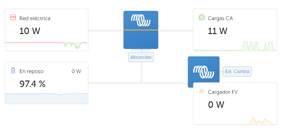
It is configured to have an AC grid reference power of 10W. In this way, consumption is supplied by the grid during the night and battery discharge is prevented.

vrm-portal1.png

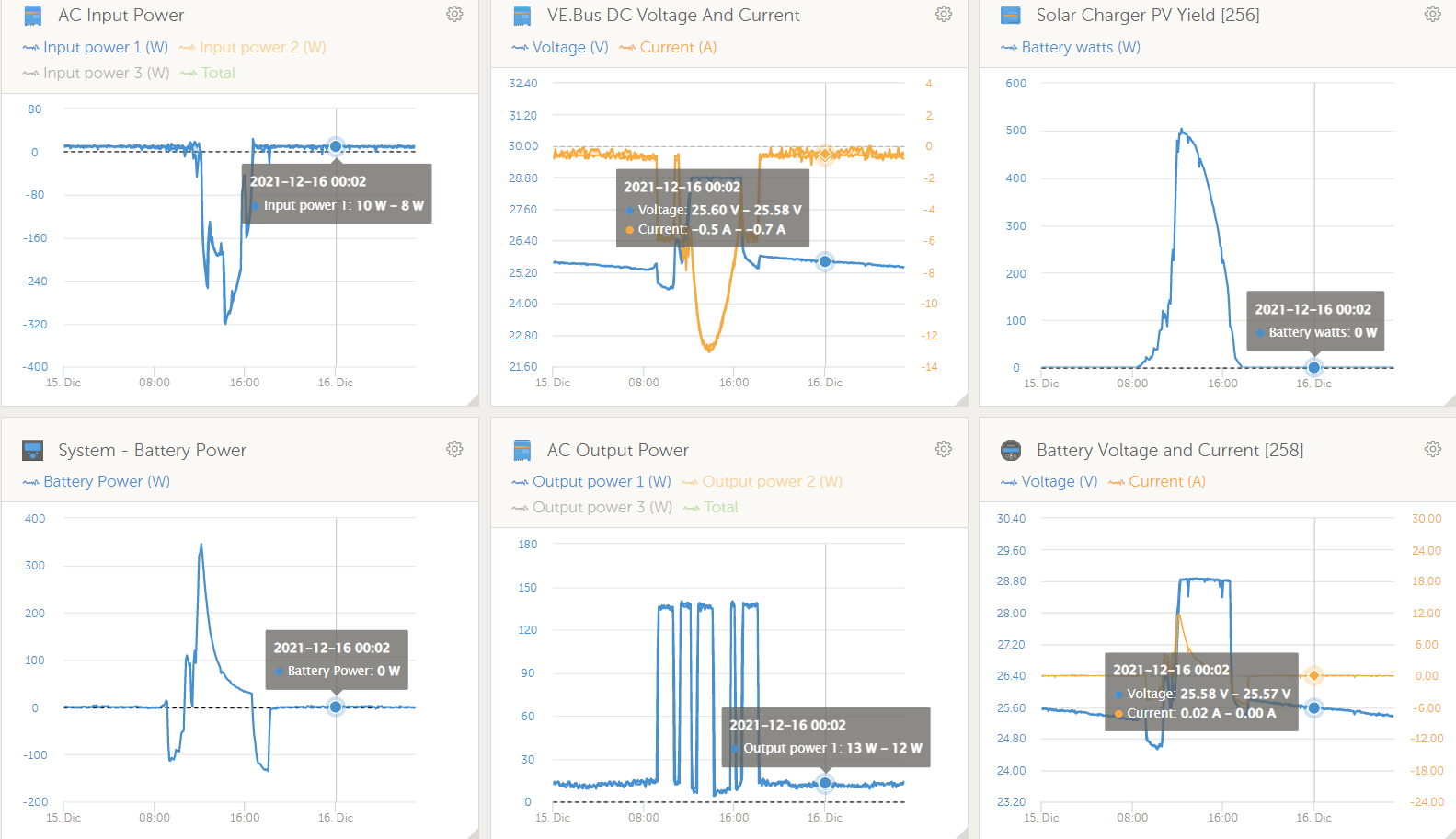
As can be seen, during the night, the power in the batteries is 0, as well as their current, i.e., they are not discharging. However, a negative current appears on the DC bus.

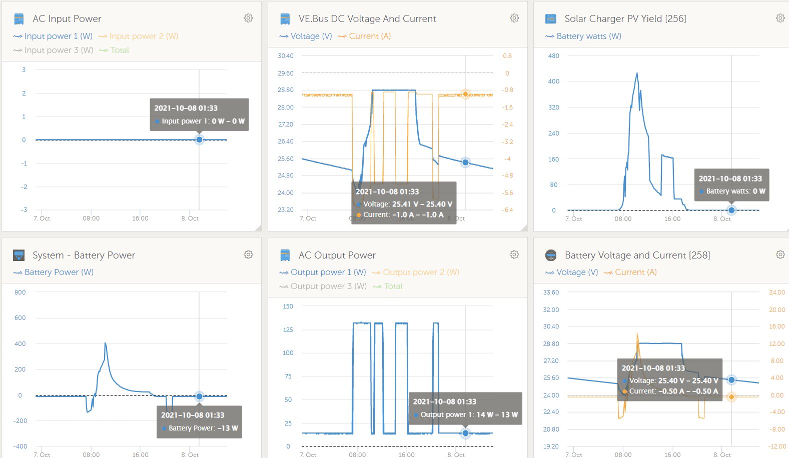
On the other hand, I did another experiment by disconnecting the AC input power to the Multiplus. In this case, during the night, the batteries are discharging since there is no grid support. In this case the batteries supply the consumption of the loads, but it is observed that the DC bus power is higher than that provided by the batteries.

vrm-portal2.png

Do these measurements make sense?

As far as I understand, in the first case (with grid support), the DC bus should be practically null since the consumption of the loads is being supplied by the grid and in the second case (without grid support) the power in the DC bus should be equal to that of the batteries and not higher.

Thank you very much.

ESSVRMmultiplus ve.busVE.Bus
vrm-portal3.png (44.1 KiB)
vrm-portal1.png (184.8 KiB)
vrm-portal2.png (172.1 KiB)
2 |3000

Up to 8 attachments (including images) can be used with a maximum of 190.8 MiB each and 286.6 MiB total.

1 Answer
Alexandra avatar image
Alexandra answered ·

@Mario_99

There is no measurement device on the DC bus like a shunt, so the dc measurement is an assumption, or a calculation not an actual measurement.

That is why you use the bmv for these things, especially the smaller loads as a shunt is more accurate.

On the AC side the measurement is not very accurat under 4Amps as well because of the design of the sensing components used. (One of the reasons why the input current limit is a certain minimum amount). So that side will also be not as accurate either in the range you are testing it

4 comments
2 |3000

Up to 8 attachments (including images) can be used with a maximum of 190.8 MiB each and 286.6 MiB total.

mario-99 avatar image mario-99 commented ·

Thank you very much for your response.

Are the measurements of the AC input power at the Multi, as well as the power demanded by the loads at the output also assumptions?

0 Likes 0 ·
kevgermany avatar image kevgermany ♦♦ mario-99 commented ·
AC In is the power from the grid going into the multi. AC Out is the power going out of the multi - Grid power plus Inverted AC from the DC sources
0 Likes 0 ·
mario-99 avatar image mario-99 kevgermany ♦♦ commented ·

I know. I simply ask if that is measured by the Multi or is that also an assumption.

0 Likes 0 ·
Alexandra avatar image Alexandra ♦ mario-99 commented ·

It does measure using a CT style sensor but is is not accurate under 4amp loads, depending on the model.


If you want alot of accuracy on the ac side you need a shunt based meter like the carlo gavazzi ones.

0 Likes 0 ·