question

Mike Dorsett avatar image
Mike Dorsett asked

Interfacing with Multis - Mk3 and BOL

Just looking into how to control a multi - Multiplus set up whilst charging Lithium batteries. This question applies both to multiplus in parallel, and multiplus in a three phase group.

If you are charging from grid connect solar in either of the above situations, you need to control the PV output when the battery approaches full charge. Traditionally this is done by a grid frequency shift - either directly to 52Hz or on a linear ramp from 51 to 52Hz whereby the PV inverter detects the frequency and regulates it's output accordingly.

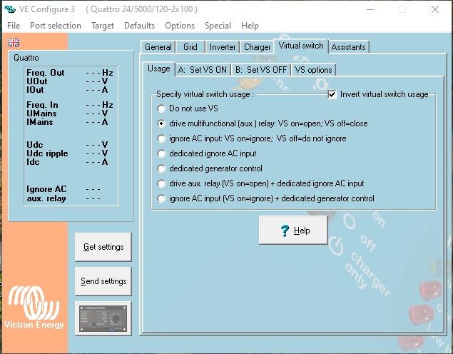
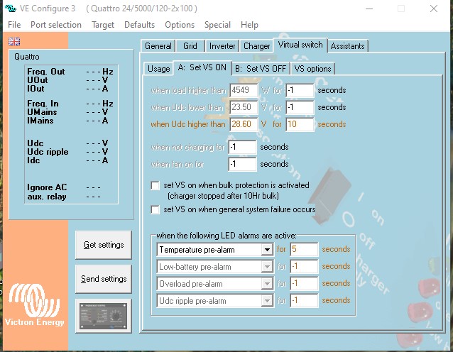
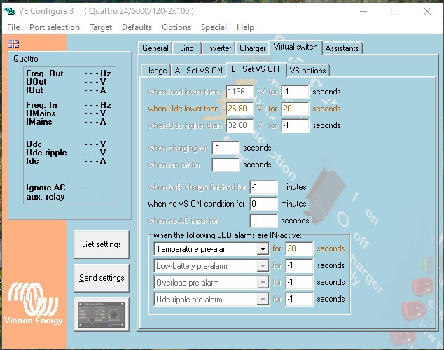
If all cells are in balance, this can be done with the virtual switch setting - shifting on battery voltage. If, however, there is one weak cell, and the cell voltage approaches maximum, the battery total voltage will be well under the limit set in the virtual switch.

The only way this can be controlled is from the BMS which knows the state of each cell.

So, the BMS needs an interface either directly to the PV inverter (if it has one) or to the Multiplus - which would be the preferred solution. This would have to use the Mk3 interface. Looking at the technical information for the Mk3 protocol V3.14; I see there is now a new command (not available to the Mk2) in section 6.4 Battery Operational Limits (BOL)

Can some one please tell me if this works whilst the Multi's are charging from the AC-out i.e. charging from grid connect solar, and how this actually regulates the charging? - or does this only work whilst the Multi's are charging from AC in - i.e. from generator.

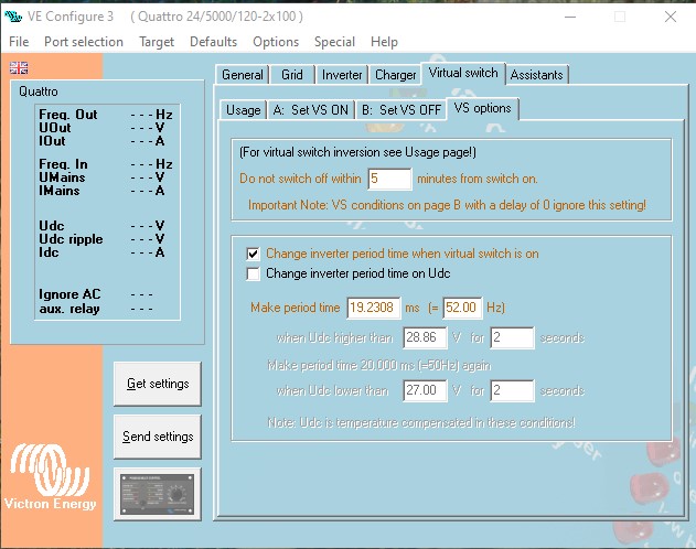
If this does not work to regulate solar charging, is it possible to update the inverter period by setting RAM variable (7)? can this be done without resetting the inverter system? Logic is confused here, because the virtual switch can do this, and apparently there is also an assistant that can be loaded to do this (this has some reported issues and is not easily configurable) BUT would one need to update all inverter period variables simultaneously? Is it possible to do this ? or would one just update the master, and let this control the Slaves?

Multiplus-II3 phasemultiplus in parallelMK3
2 |3000

Up to 8 attachments (including images) can be used with a maximum of 190.8 MiB each and 286.6 MiB total.

3 Answers
Paul B avatar image
Paul B answered ·

Hi, you can use the VE-BMS unit to do what you are asking

(Note this is NOT recommended by victron AT ALL -do this at you worn risk to do this but it works fine) How ever I have used them quite a lot for this perpose and they the units work very well, you will not get any support from victron on doing this though


this unit is connected to the inverters VE-BUS tells through the VE-BUS and the inverters are told when they need to stop charge or inverting.

ie if one cell goes high then the BMS opens a relay and this then brakes the charging circuit on the VE-BMS unit. (as a example) thus turning charging off, and then if the inverters have grid tie attached the frequency goes high and the grid tie derate or turn off.

The VE-BMS has 3 Normally closed looped circuits, so if any of these go open circuit then the below happens

the one for low cell voltage trigger goes open (this tells the inverters to stop Inverting)

the one for High Cell Voltage trigger goes open (tells the inverters to stop charging)

the one for Temp goes open ( turns charging and inverting off )


another way is to use the 2 signal BMS assistant and feed these from the batteries BMS as well

2 |3000

Up to 8 attachments (including images) can be used with a maximum of 190.8 MiB each and 286.6 MiB total.

Mike Dorsett avatar image
Mike Dorsett answered ·

Hi Paul, This is not quite what I'm intending. I need to shift the Frequency of the inverter system to control the PV output, NOT turn the system from inverting to grid. This will be in a totally off grid system, and I need to regulate the solar charging.

2 comments
2 |3000

Up to 8 attachments (including images) can be used with a maximum of 190.8 MiB each and 286.6 MiB total.

Paul B avatar image Paul B commented ·
Mike this is what it does, if charging is required to be STOPPED then the VE-BMS tells the Multi/quattro to stop charging and THUS the Frequency will change upwards to tell the grid tie to derate or stop completely until the BMS until the BMS closed the circuit again then charging will resume


0 Likes 0 ·
Paul B avatar image Paul B Paul B commented ·
Mike my own home site is setup this way with a VE-BMS unit. with one 48/5000 and a grid tie unit, and I only connect to the grid if I am short of power, so its basically a off grid setup.

You are welcome to browse the setup if that's of help to you. just met me know and ill send you a vrm invite.

When replying - use "viewable by original poster" option and send me your email address

0 Likes 0 ·
Mike Dorsett avatar image
Mike Dorsett answered ·

I think that I've found a partial solution to this. The answer from Paul B made me take another look at the virtual switch settings possible in VE configure:

vs-use.jpg

The VS use was selected as AUX relay - this was configured on a FAKE system.

vs-on.jpg

The VS-ON options are set for High DC voltage (all cells 95%+) and temperature pre-alarm.

vs-off.jpg

The VS-Off options are also set for a lower DC Voltage, and clear Temp pre-alarm.

vs-opt.jpg

The VS-Options are set not to operate within 5 minutes of switch on, and to change the inverter time period when active to 52Hz, rather than changing time period on DC Voltage.

So far, it seems to be a long winded way of changing the period on V DC, BUT:

1) The inverter frequency is also changed on Temperature pre-alarm,

2) The VS CAN be activated by remote, over the VE -Bus using the Mk2.

All that remains now it to try this out on the system - at a time when it won't annoy the users. I also have to find a backup inverter, as the only windows machine running VE-Config does not have a battery any more, and the mains power is likely to go off during the re-configuration. If the Mk2 doesn't change the frequency, then the temp pre-alarm should, and the bms has a relay that can switch additional resistance into the temp sensor circuit, simulating a hot battery - if needed.

Does any one see a reason why this should not work?

The reason I'm calling this a partial solution is that the frequency gets a step change, so grid connected PV inverters go from 100% to 0%. which is not ideal.


vs-use.jpg (77.4 KiB)
vs-on.jpg (88.9 KiB)
vs-off.jpg (87.5 KiB)
vs-opt.jpg (81.5 KiB)
2 |3000

Up to 8 attachments (including images) can be used with a maximum of 190.8 MiB each and 286.6 MiB total.