question

pmolettiere avatar image
pmolettiere asked

Trouble switching battery protect from ve.bus bms charge disconnect

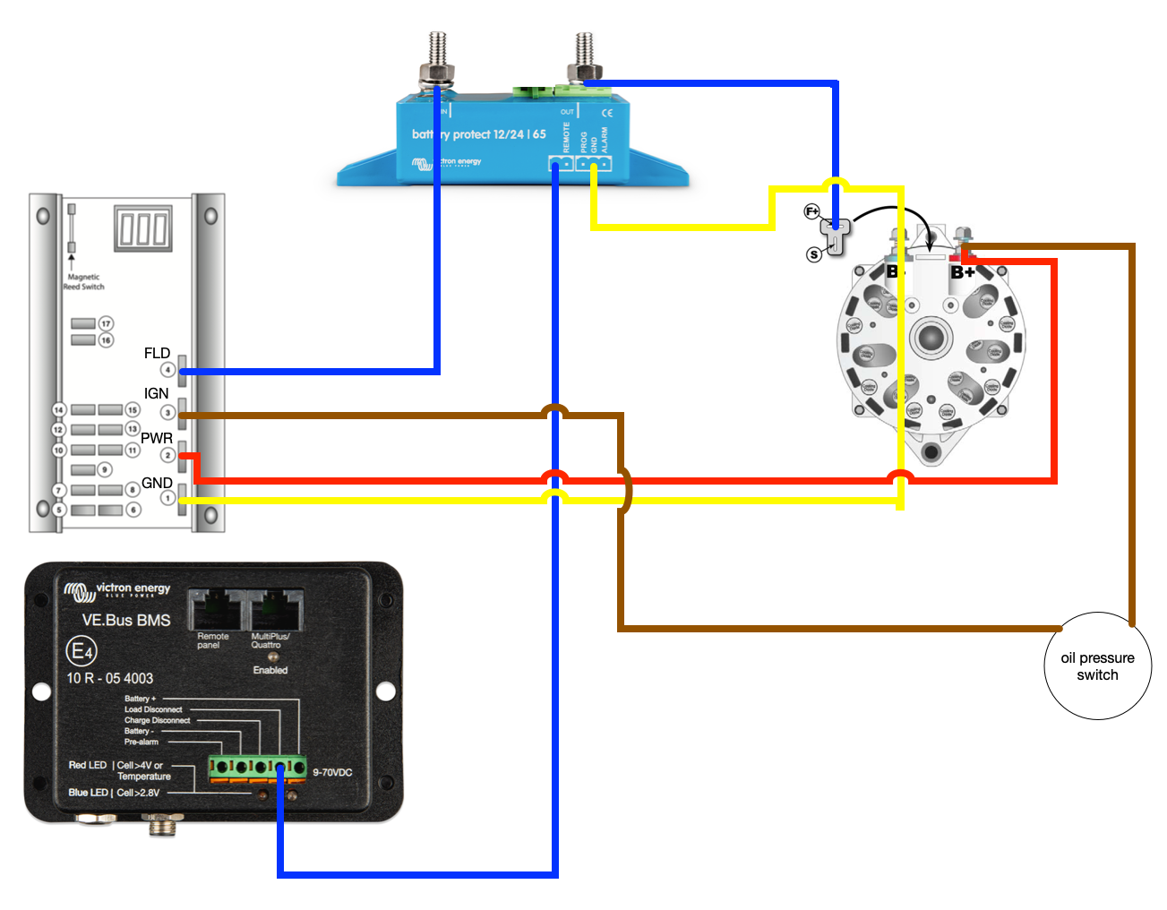
I'm trying to use a Battery Protect to switch the ignition input on an external voltage regulator, to disable alternator charging. According to the Victron manuals, if I connect the ve.bus BMS load disconnect to the battery protect remote H/+ terminal, then the Battery Protect should disconnect when the charge disconnect line floats.

I've programmed the Battery Protect to mode 0-C — the lithium mode.

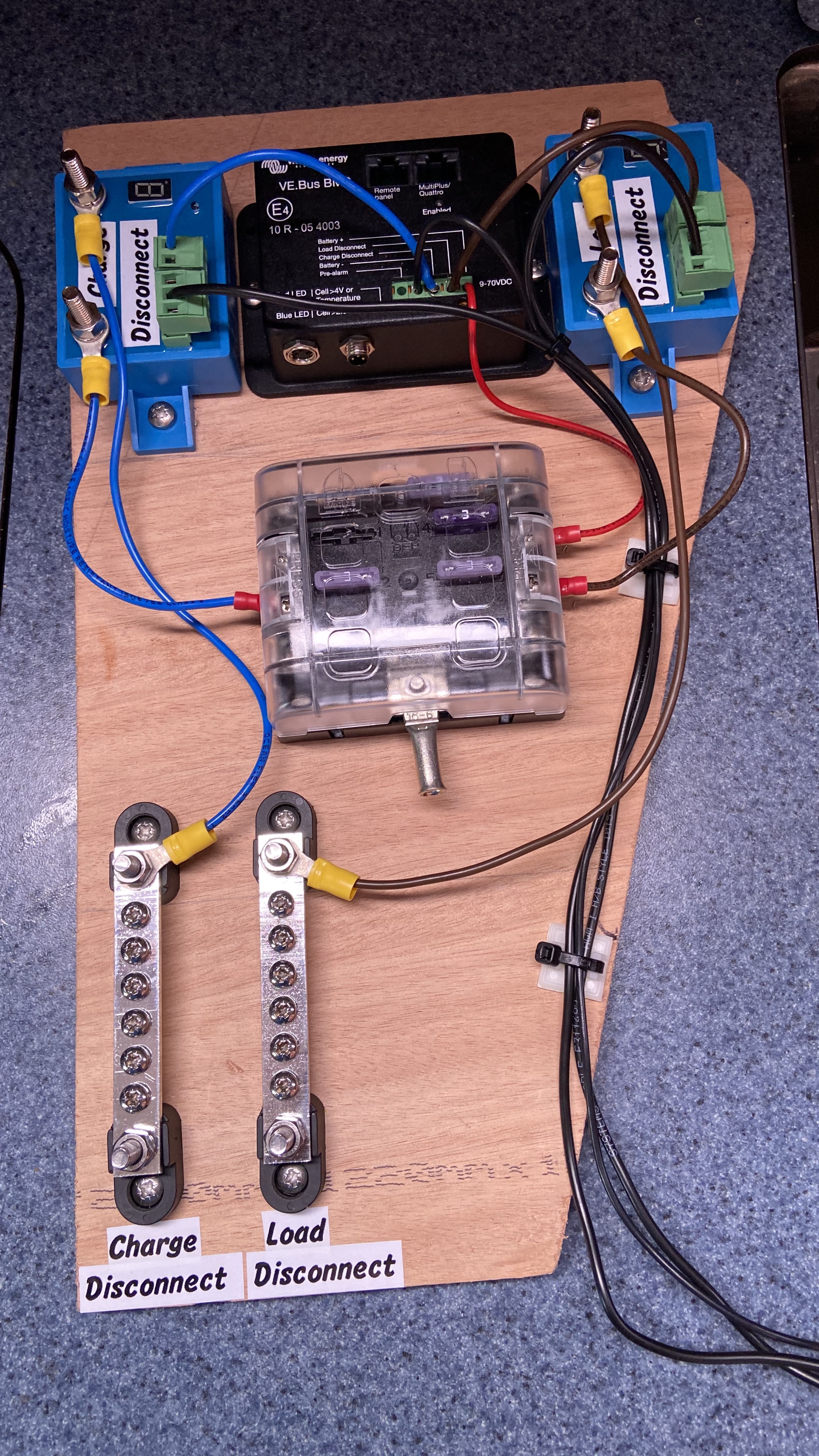
I'm trying to test to make sure this is working, but when I disconnect the BMS charge disconnect from the Battery Protect H/+ terminal, the relay continues to remain closed, and I have full voltage on both the input and output for the battery protect.

Can someone provide some suggestions?


battery chargingLithium BatteryBMSBattery Protect
2 |3000

Up to 8 attachments (including images) can be used with a maximum of 190.8 MiB each and 286.6 MiB total.

3 Answers
bathnm avatar image
bathnm answered ·

I have had similar issues. If there is not enough current flowing through the Battery Protect then it won’t actually switch off, as there is not enough current drain.

As I have a number of devices on my Charge and Load disconnect I was trying to use them to drive a charge and disconnect bus. So input connected to the 24v bus, output was all the charge or load disconnect devices and use the BMS into the H port.

However when I removed the H port I would still have a positive voltage on the output generally a few Volts below the actual input voltage.

H-Pin connected


H-Pin removed


Thought I had faulty units so had them swapped and the new ones did the same. Took the new ones to the bench and tried switching a proper load of several amps and they worked perfectly.

I haven’t tested to see what the minimum amp draw through the unit is to trigger a switch, but as said will need to be enough to drain the MOSFETS.

BTW my reason for doing this is I could not get out of Victron how many devices you could feed direct from the BMS. On the charge disconnect I need to signal 2xMPPTs, 2xOrion TRs, alternator controller and a few other devices, and didn’t want to overrun the max current the charge disconnect can support of 10mA. As it happens with all these devices the draw is around 3mA and so didn’t need the SBP 65 anyway.

I suspect when the alternator is being driven hard the SBP will switch, but as the field current drops as the alternator is required to generate less current the likely hood of it switching will reduce as less current is flowing!


You may well struggle with an automotive relay as the Charge Disconnect port has a 10mA load max and I suspect automotive relays will need likely double that

As suggested cut the power to the controller, or get an opto-coupler controlled relay as the opto-coupler will draw very little current. This would be my preferred route as I don’t trust the SBP65 to work on small loads and the power supply connection might not always have enough current draw to trigger a switch of the SBP65


Hope that helps


1603520618767.jpeg (3.1 MiB)
1603521176083.jpeg (565.1 KiB)
1603521203127.jpeg (579.9 KiB)
1 comment
2 |3000

Up to 8 attachments (including images) can be used with a maximum of 190.8 MiB each and 286.6 MiB total.

pmolettiere avatar image pmolettiere commented ·
Wow! Great answer! What you're outlining here is exactly what I'm trying to do. I ended up taking a slightly different path to the solution. Rather than changing the schematic to suit the needs of the BatteryProtect, I just swapped the part out. McMaster has solid state relays which switch with less than 10mA, and control up to 20A, which is plenty for my application. Otherwise, this is exactly the layout — charge disconnect to relay, relay switches battery pos to bus to bring various charge disconnect inputs high on other devices (MPPT, alternator external voltage regulator ignition, etc.).
0 Likes 0 ·
Matthias Lange - DE avatar image
Matthias Lange - DE answered ·

Did you installed the Battery Protect in the right orientation? In your case the alternator have to be connected to the input and the battery to the output.

1 comment
2 |3000

Up to 8 attachments (including images) can be used with a maximum of 190.8 MiB each and 286.6 MiB total.

pmolettiere avatar image pmolettiere commented ·

I'm not using the Battery Protect to switch the charging current. I'm using it to switch the field to the alternator. My understanding is that disconnecting the charging current from the alternator while it's sending full current would destroy the alternator diodes.

The diagram below shows what I'm trying to do more clearly.

For testing purposes, the regulator ignition is wired to battery positive. The alternator is pulling about three amps, regardless of whether the load disconnect from the ve.bus BMS is present or not. I would expect the Battery Protect to disconnect when the remote+ is free floating.

The Battery Protect is in mode 0-C.

I'm considering just replacing the Battery Protect with a simple automotive relay, but figured I'd ask here first.

Thanks

0 Likes 0 ·
bpquestiondiagram.png (463.7 KiB)
lblanchette avatar image
lblanchette answered ·

pkys discusses this. Short answer use BP to disconnect power rather than ignition.

2 |3000

Up to 8 attachments (including images) can be used with a maximum of 190.8 MiB each and 286.6 MiB total.