Hi, I am now using Venus to monitor my system. However, I was surprised to see that the diagram of connected devices is incorrect. I am guessing it was done to try and oversimplify things for beginners?
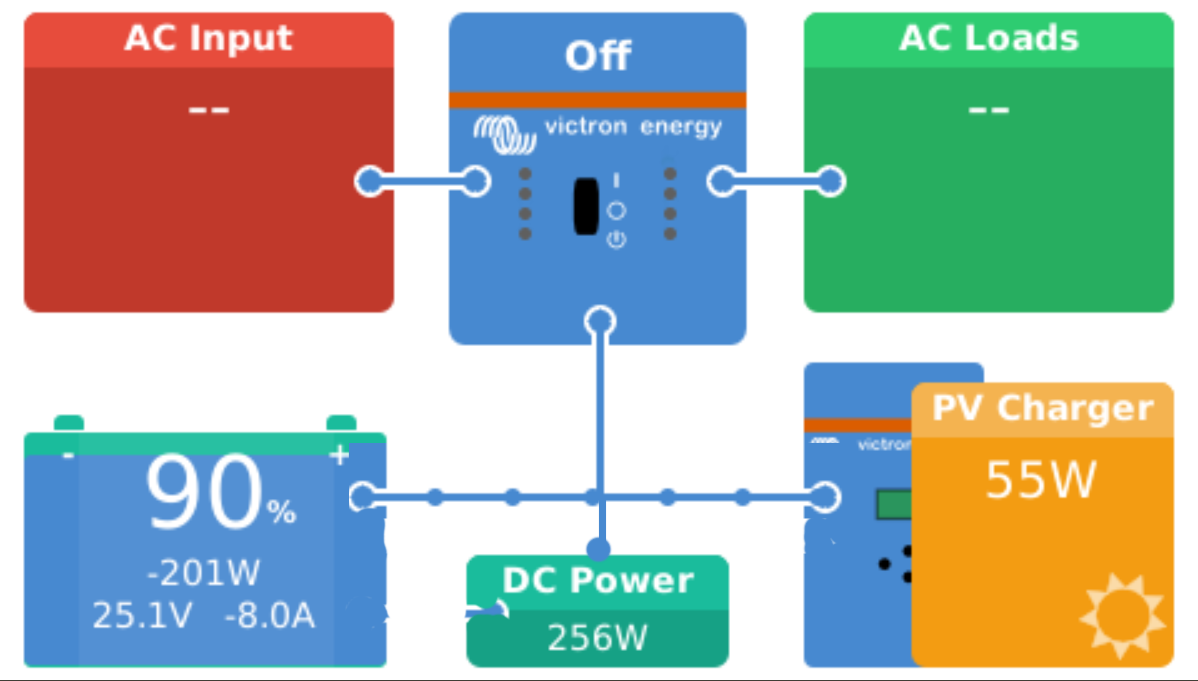
This is how my system looks right now:
Firstly, this diagram has inconsistently applied design principles. The AC inverter load is not connected to the battery, but rather to a central "busbar", so by that formalism, the DC load also should be.
Secondly, this diagram prevents the system from being accurately represented, for example in the case where the solar system is producing enough power to simultaneously charge both the battery and power the DC load. In that case, this diagram depicts the power going through the battery first, and then to the DC load, which physically wouldn't happen - electrons being moved from the solar charger would literally never pass though the battery.
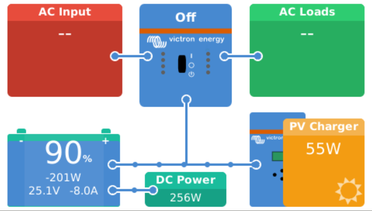
Would it be possible to correct this diagram? I am being driven mad by this nonphysical depiction. This is how I believe it should look: