question

mario-vdb avatar image
mario-vdb asked

Multiple tanksensors switching one Cerbo gx relay output in Node-Red

For a some days i've been trying to get this to work but can't seem to figure it out.

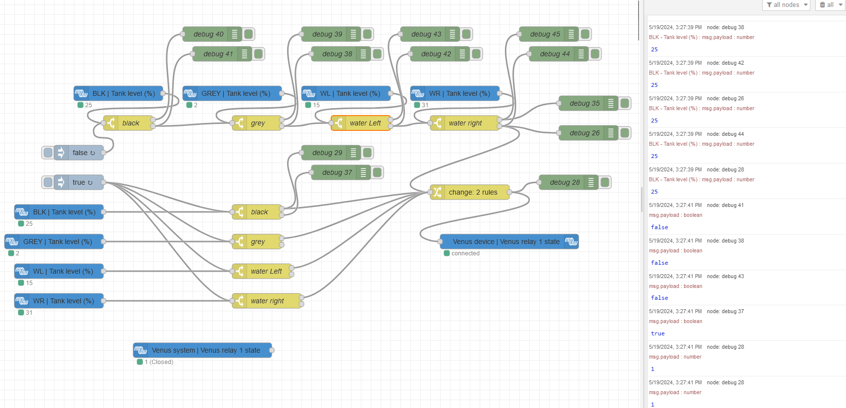
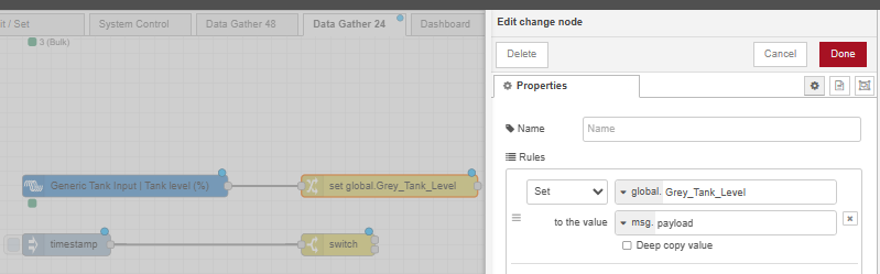
The Cerbo gx has 4 tanksensor input. In this project I'm using all 4 inputs, input 1 black water, input 2 grey water, input 3 freshwater left, input 4 freshwater right.

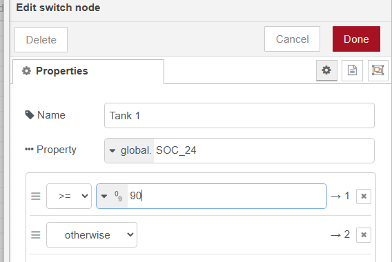
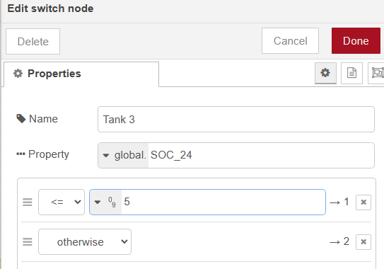
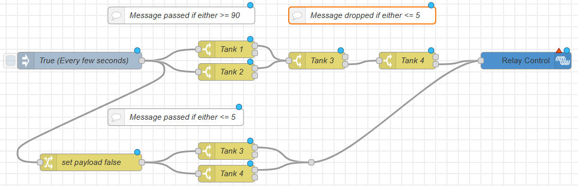
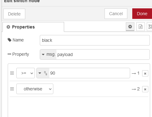
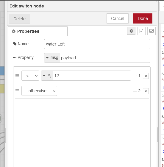
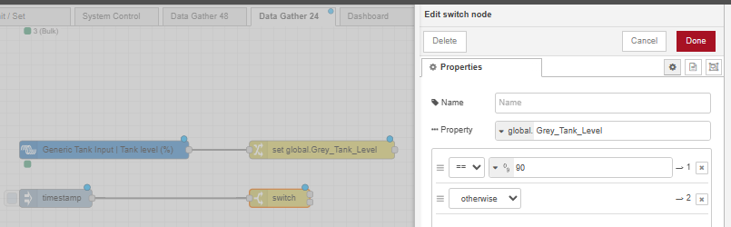
When one or both of the waste water tanks reach 90% or more I want to switch the cerbo relay 1 on. When one or both of the freshwater tanks reach 5% or less I want to switch the cerbo relay 1 on. So the waterpump doesn't overfill the tanks or is running dry.

When all of the tanksensor are within the limits, waste water 0-90% and freshwater 5-100%, the relay should be off and the pump should be able to run.

Right now i'm trying to get it working with some of the "And" en "Or" gates but for some reason they don't seem to work like on a Siemens Logo!. I've tried setting different topics, tried booleans and payload messages, for some reason the relay only want to turn ether on or off or still turn on or off when an other tanksensor pushes his information.


When I started this I thought it wouldn't be this difficult, but it feels like I'm running in circle now. I'm not really in to Javascript and so, I've worked with Siemens Logo! and so.


Does anyone have a idea how to get a flow like this working?

cerbo gxNode-REDtank monitor
2 |3000

Up to 8 attachments (including images) can be used with a maximum of 190.8 MiB each and 286.6 MiB total.

6 Answers
Alistair Warburton avatar image
Alistair Warburton answered ·

Been there...

There are innumerable ways to do this sort of stuff and yes, logic gates are a valid approach but combining several messages into a single one that contains all the required data for those gate to work is tedious and not at all intuitive, as you will have discovered.

I use and recommend the following strategy...

Collect your tank data as and when it arrives, store those values in Flow or Global context using a change node to set the variables when data arrives.

I would also recommend initializing those variables at startup, setting a default value once. Persistent context storage is a good plan too but I don't know if that is available when running on a Cerbo.

Now the data is available to any node within context...
You can use a function node to perform all your logic in one node or, for a clearer picture of what is going on and to avoid actual code, you can use switch nodes to do the work.

Set a trigger node to fire periodically. Route its message through switch nodes that use the context data to determine which output the message will be routed to.

In your case, 2 switch nodes with the top output active when either tank is full and two copies to switch nodes with the top output active when a tank is empty. in all cases the second output is set to otherwise and acts as a default. (No tank/s so just used my first CV, SOC_24 as a placeholder...)

1716025597840.png


1716025839843.png

Now just hook then up...

1716026642583.png

Simple and clear... You could even use context vars for your setpoints...

Give me a shout if you need help...


1716025597840.png (16.0 KiB)
1716025839843.png (15.1 KiB)
1716026642583.png (51.4 KiB)
2 |3000

Up to 8 attachments (including images) can be used with a maximum of 190.8 MiB each and 286.6 MiB total.

mario-vdb avatar image
mario-vdb answered ·

Thank you for the reply Alistair!

For some reason the True of False that's being send every 5 second only seem to travel on the output of the switch configured at "otherwise", accept with the water left en right sensor.

The switch for the water sender should the false on the "otherwise" output, but simply doesn't.

schermafbeelding-2024-05-19-145942.png

As i have no clue how to store information in Node-red so this was my approach.

Every switch is the same for black and grey it's ">=90" for output 1 and "otherwise" for output 2

For Water it is "<=12"for output 1 and "otherwise" for output 2schermafbeelding-2024-05-19-150210.pngschermafbeelding-2024-05-19-150241.png

In my thought running all the number 1 outputs parallel the relay should switch on when on of the tanks reached the value setting. And running all of the "otherwise" outputs in series should turn off the relay when all values are within limits.

As you can see the tank sensor are within limits but the relay is still set.

Also the relay only answers to "0" to turn off and "1" to turn on, that's why I added the last switch that translate "false" to 0 and "true" to 1.


At this moment I have variable resistor on the black and grey input, but the water tank inputs are fixed resistor, that's why the minimum is 12% for the water tanks right now.


Is it a possibility for you to upload the .json file, I think that would help a lot.

Thank you for your input this far, it nice to have someone else's input in this!


2 |3000

Up to 8 attachments (including images) can be used with a maximum of 190.8 MiB each and 286.6 MiB total.

Alistair Warburton avatar image
Alistair Warburton answered ·

OK... That a node red thing... Each node only acts on what it gets in a message when it gets it, there is no remembering the last massage and using that info to, in this case, route the next one.

Since you need to inspect multiple conditions to make a decision any messahe yoiu want to process has to contain all the information needed to make that decision.

There several approaches to do this, including switch nodes that you send a message to set and they stay in that state until you tell them otherwise... See this. It is easy to use and intuitive, just like a switch, set it with a message, that isn't passed to its output, and it will pass or block anything else.

Storing data to use later is easy just use a change node and write payload to a global context variable...

1716126744812.png

Now you can do this

1716126690873.png

It is way less mucking about and if you always collect data and store it you can then use it in any combination anywhere... This my data gatherer for my 24 system, cant remember why I wasn't storing bus state but I only use it for a label anyway.

1716126982424.png

The change nodes on the left store the Global context vars, the Changed nodes prevent unwanted processing by only passing changed info to the dashboard.

1716127156775.png
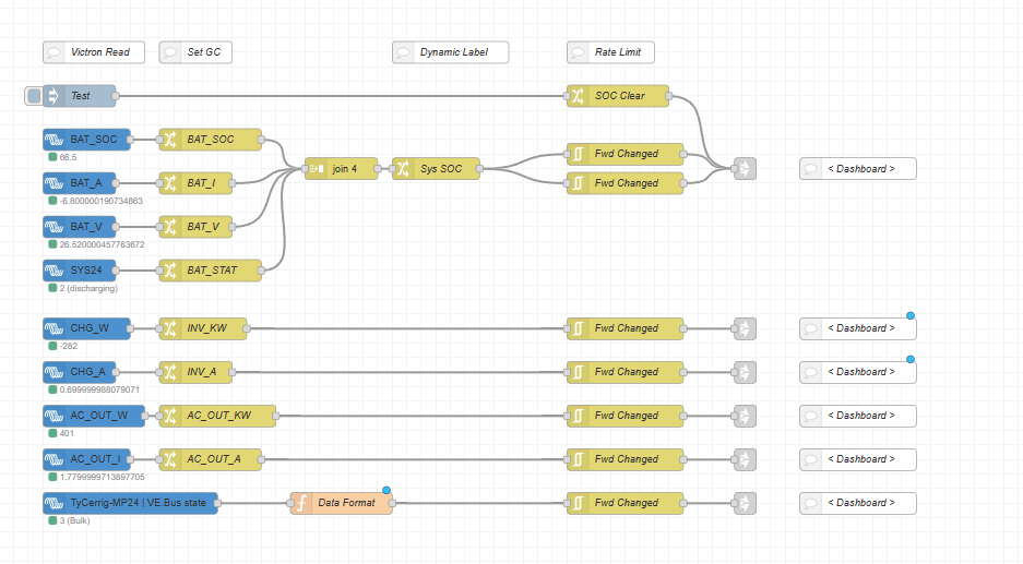
I will send you some code shortly... But its worth sticking with it to get your head around how Node Red works.


1716126690873.png (24.0 KiB)
1716126744812.png (25.3 KiB)
1716126982424.png (74.3 KiB)
1716127156775.png (38.3 KiB)
2 |3000

Up to 8 attachments (including images) can be used with a maximum of 190.8 MiB each and 286.6 MiB total.

Alistair Warburton avatar image
Alistair Warburton answered ·

To give you code I need to know which tank sensor is which... Ideally

2 |3000

Up to 8 attachments (including images) can be used with a maximum of 190.8 MiB each and 286.6 MiB total.

Alistair Warburton avatar image
Alistair Warburton answered ·

This flow is working...
Disconnect your tank sensors so the the injection points will work for testing.

flows.json.txt Rename this to flows.json then import as a new flow.

Give me a shout if you have any problems with it.


Enhancements...

Use the sensor fault outputs to do something, stop pump, tell you about the issue, whatever.

Add an initial inject, just the once when the system boots, to set all the global's to within range. If you adjust the test 50 inject so it fires once at startup you will have done this.


flowsjson.txt (23.6 KiB)
2 |3000

Up to 8 attachments (including images) can be used with a maximum of 190.8 MiB each and 286.6 MiB total.

mario-vdb avatar image
mario-vdb answered ·

Hi Alistair,


After a bit of testing it seems to be working perfect! Thank you so much!

I have restarted the Cerbo multiple times in multiple ways and it seems that all keeps working right away.

I removed the top limit on the water tanks, cause the pump is still aloud to run when the water tanks are full.


The Cerbo is set to a risistive input of 0-300 ohms, 0 ohm being 0% and 300 should be 100% full. If the resistive range is out of the limit of the Cerbo it won't give any signal, on the screen it simply says "Disconnected"


This has been a nice way to start learning about this, sometimes I'm amazed at the amount of way you can solve a problem.


Thank you Alistair!

1 comment
2 |3000

Up to 8 attachments (including images) can be used with a maximum of 190.8 MiB each and 286.6 MiB total.

Alistair Warburton avatar image Alistair Warburton commented ·
You are welcome, we all need a leg up sometimes...
0 Likes 0 ·