question

enodev avatar image
enodev asked

DVCC with VE.Bus BMS v2, Cerbo GX, MPPT Smart Solar 100/50, Multiplus 12/1600

I have a simple system with Multiplus 12/1600, Victron Smart LiFePo batteries, MPPT 100/50, and VE.Bus BMS v2. All working great.

Originally the VE.Direct remote on/off cable was used so that VE.Bus BMS v2 would shut down the MPPT when needed.

I have now added Cerbo GX to the mix and replaced the VE.Direct remote on/off cable with straight VE.Direct cable.

If I understand everything correctly (which I may not) I need to enable DVCC on Cerbo GX to make it control MPPT based on what is received over VE.Bus from VE.Bus BMS v2.

With DVCC disabled, MPPT correctly shows on Cerbo GX Console that it is:

  • "Networked: No"
  • "Controlled by BMS: No"

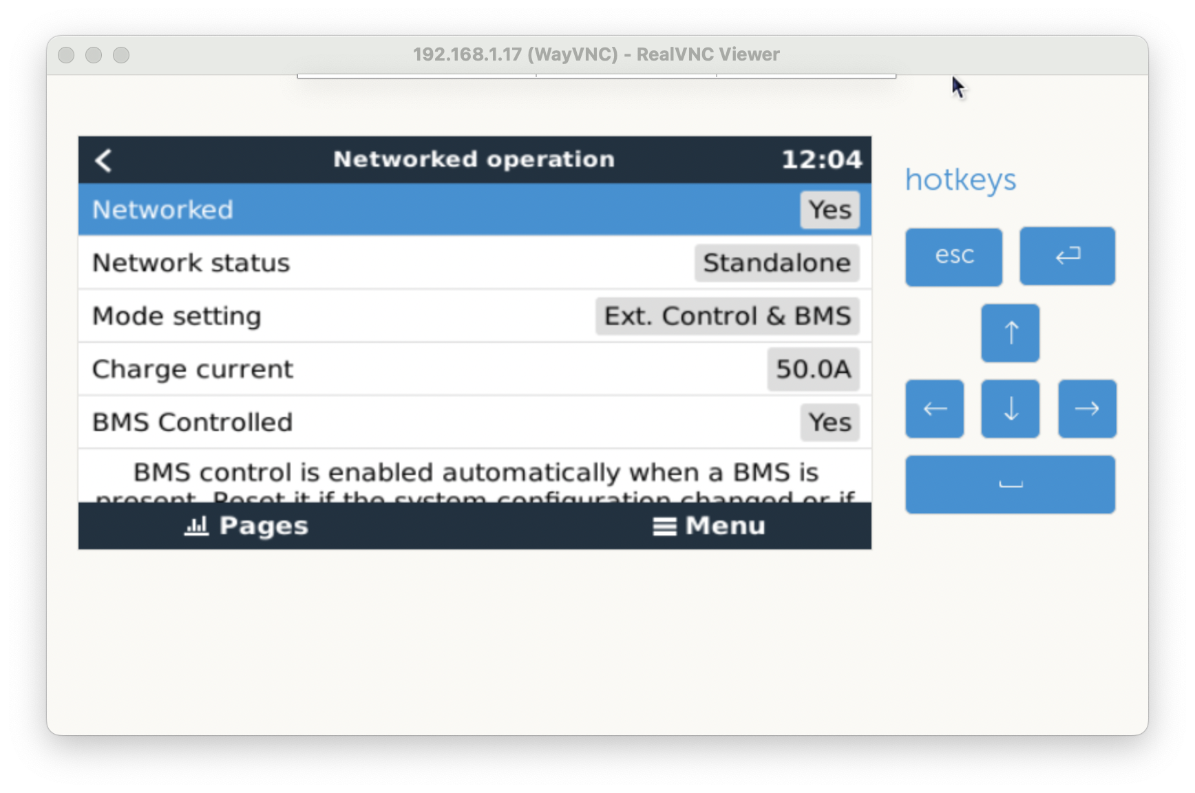
With DVCC enabled (SVS + SCS), MPPT correctly shows on Cerbo GX Console that it is:

  • "Networked: Yes"
  • "Controlled by BMS: Yes"

screenshot-2024-01-19-at-120421.png

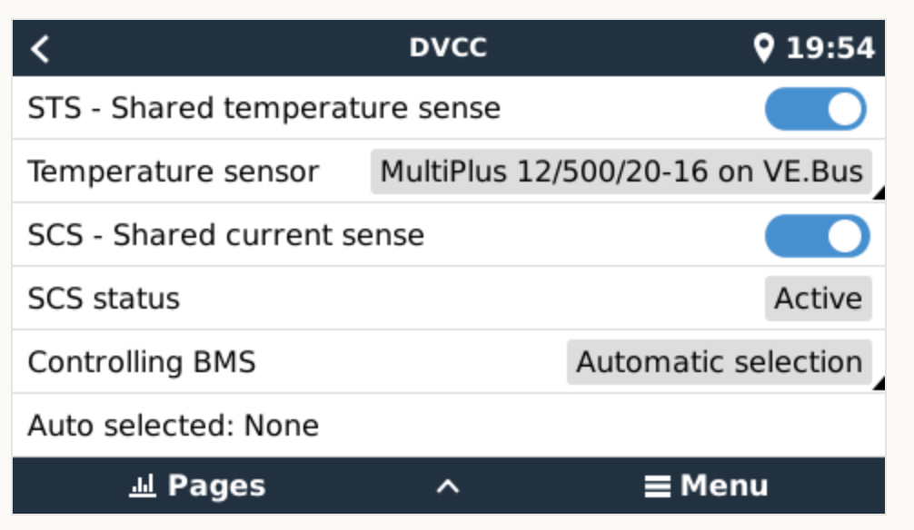
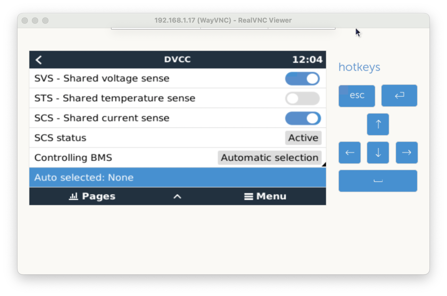
When I examine Cerbo GX Console Settings/DVCC. The controlling BMS set to Automatic Selection, yet Auto Selected indicates None. This is very confusing as I believe it should display VE.Bus BMS v2 to be the controlling one.

screenshot-2024-01-19-at-120457.png


Is my understanding correct? I checked the gui-v2 and I believe it does not show properly there either, very probably because this is obtained from DBUS which does not contain the proper value.

I found this (already closed) bug report https://github.com/victronenergy/venus/issues/901 which sounds like it is touching this area.

So is this a bug? Or expected behaviour?

EDIT: I should add that the system is using SmartShunt as auto detected Battery Monitor correctly.

screenshot-2024-01-19-at-121351.png

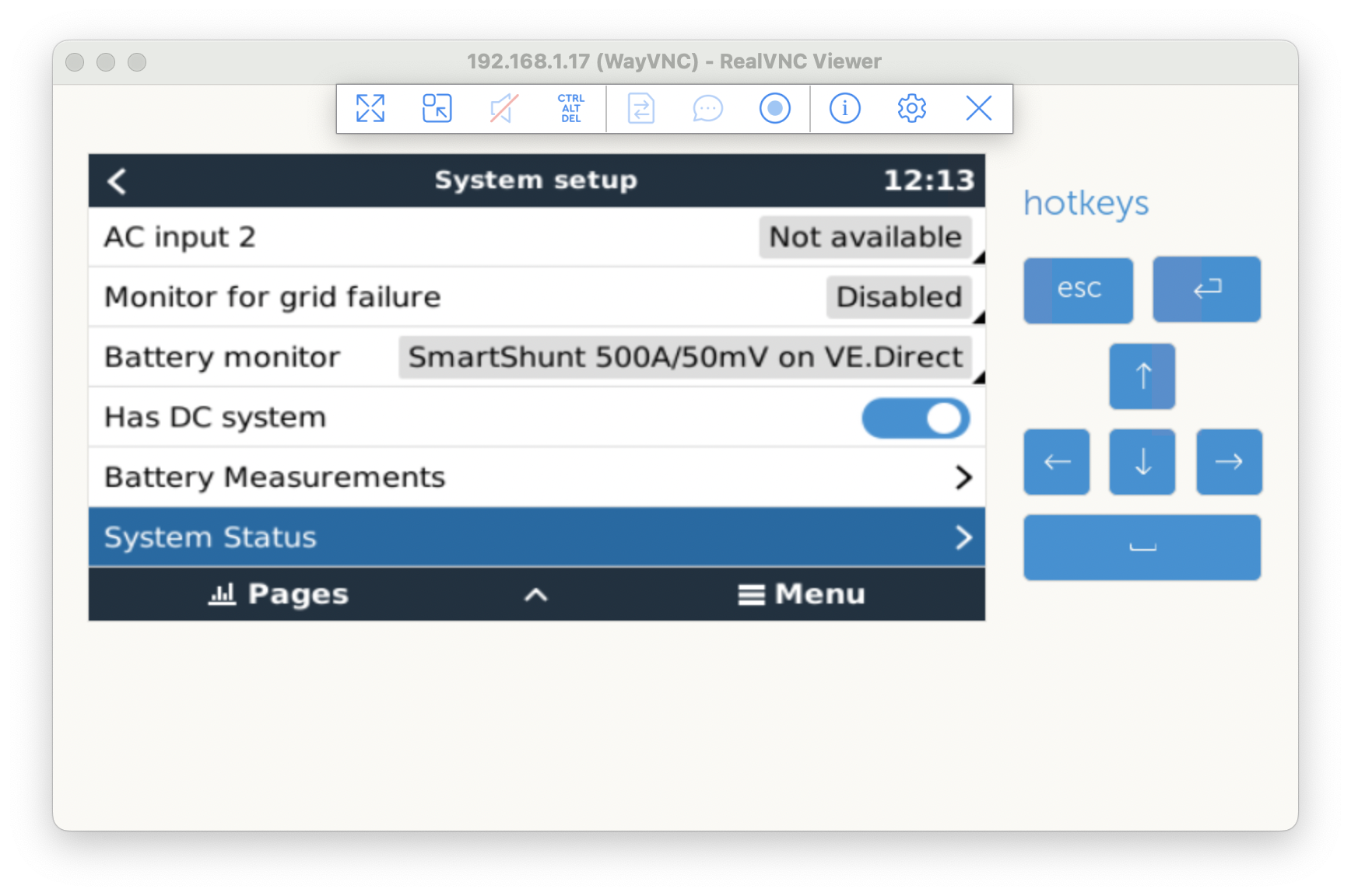
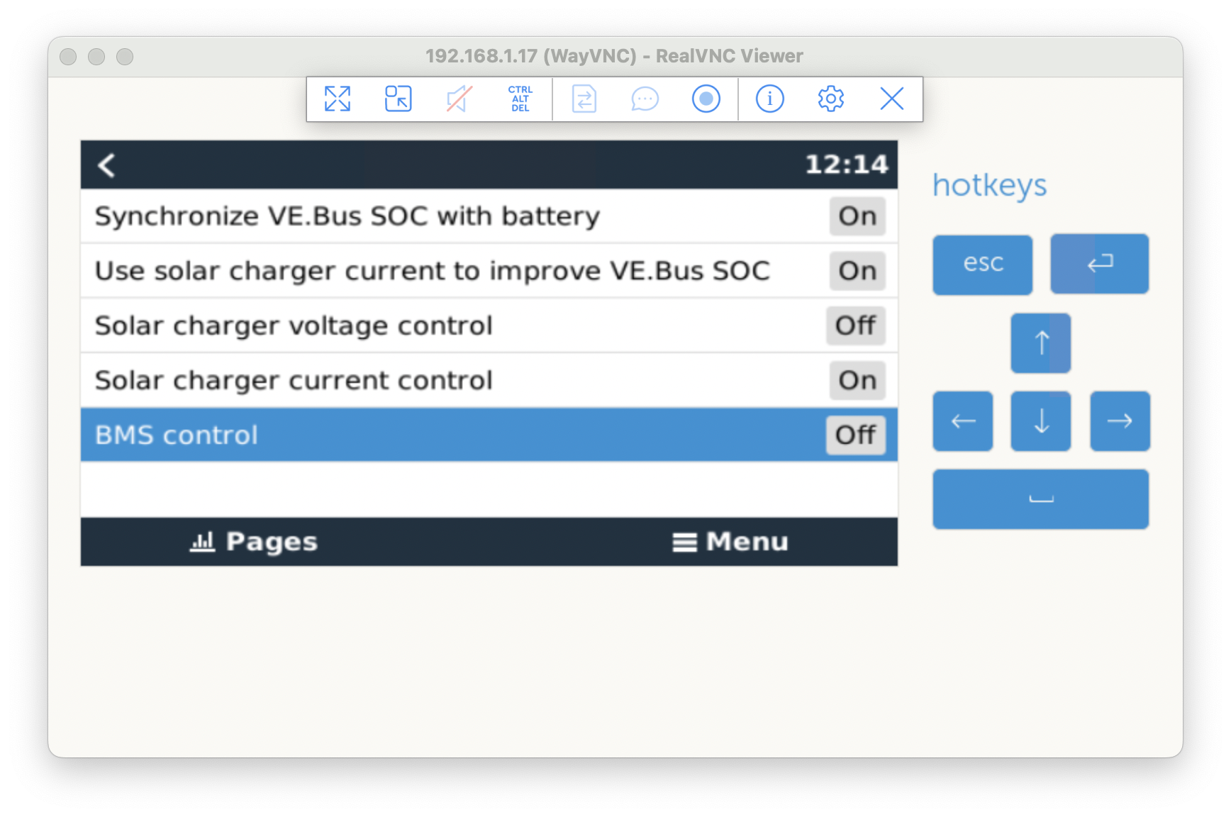
And that advanced System Status Panel indicates that BMS control is OFF. Which is now super confusing...

screenshot-2024-01-19-at-121415.png

thanks,

Martin

MPPT SmartSolarmultiplus ve.busVE.BusDVCC
2 |3000

Up to 8 attachments (including images) can be used with a maximum of 190.8 MiB each and 286.6 MiB total.

4 Answers
grandalaskaexp avatar image
grandalaskaexp answered ·

Hi, have you confirmed all of your device's firmware's are up to date.


1 comment
2 |3000

Up to 8 attachments (including images) can be used with a maximum of 190.8 MiB each and 286.6 MiB total.

enodev avatar image enodev commented ·

yes of course, same behavior on latest stable 3.13 as well as latest release candidate as of today…

0 Likes 0 ·
henri-bergius avatar image
henri-bergius answered ·

I’m seeing the same on our system. VE.Bus BMS v2, MultiPlus, Cerbo GX running 3.13.

img-1348.jpeg


img-1348.jpeg (160.2 KiB)
2 |3000

Up to 8 attachments (including images) can be used with a maximum of 190.8 MiB each and 286.6 MiB total.

bathnm avatar image
bathnm answered ·

I do not have one myself. The manual is a little sparse. See section 3.3.4

https://www.victronenergy.com/media/pg/VE.Bus_BMS_V2/en/installation.html#UUID-572043c8-0d58-edde-3cae-900bb0ffedac


The two menu options you displayed show two different views. The first you displayed is the MPPT and as far as it is concerned it is being controlled by the CerboGX, which due to the DVCC configuration supplied, is supplying Voltage and Current charging goals to the MPPT. Along with ATC and ATD signals from the VE.Bus BMS V2.

The second screen is the view of the CerboGX and what it is doing. The Controlling BMS is designed for a CAN enabled battery that is supply charge voltage and charge/discharge current limits. So what it is telling you is that the GX is not receiving any charge or discharge goals from a BMS. The VE.Bus BMS has no data related to current flowing into or out of the batteries or the voltage, therefore it cannot be controlled by that BMS. You would need the Lynx Smart BMS for this.

I hope that helps.

2 |3000

Up to 8 attachments (including images) can be used with a maximum of 190.8 MiB each and 286.6 MiB total.

enodev avatar image
enodev answered ·

@Bathnm Your explanation makes a lot of sense describing how it works internally. Thanks for writing it. If I understand everything correctly, VE.Bus.BMS v2 will:

1. send ATC and ATD over VE.Bus

2. Cerbo GX will pick ATC and ATD over VE.Bus, and will use DVCC to communicate with MPPT to start/stop charging based on ATC, probably by limiting charge current.


If true that means the system is working as expected.


However I find it super confusing that in the GUI:

1. MPPT config says "BMS Controlled: YES"

2. Cerbo GX DVCC says "Controlling BMS: None"


Technically since VE.Bus BMS v3 does not use DVCC, it is correct, but super confusing.

2 |3000

Up to 8 attachments (including images) can be used with a maximum of 190.8 MiB each and 286.6 MiB total.

Related Resources