question

clay123 avatar image
clay123 asked

Multiplus II Three Phase System Frequent restarts & shuts down when AC load added

Good day all,

Kindly requesting any assistance I can get for my system.

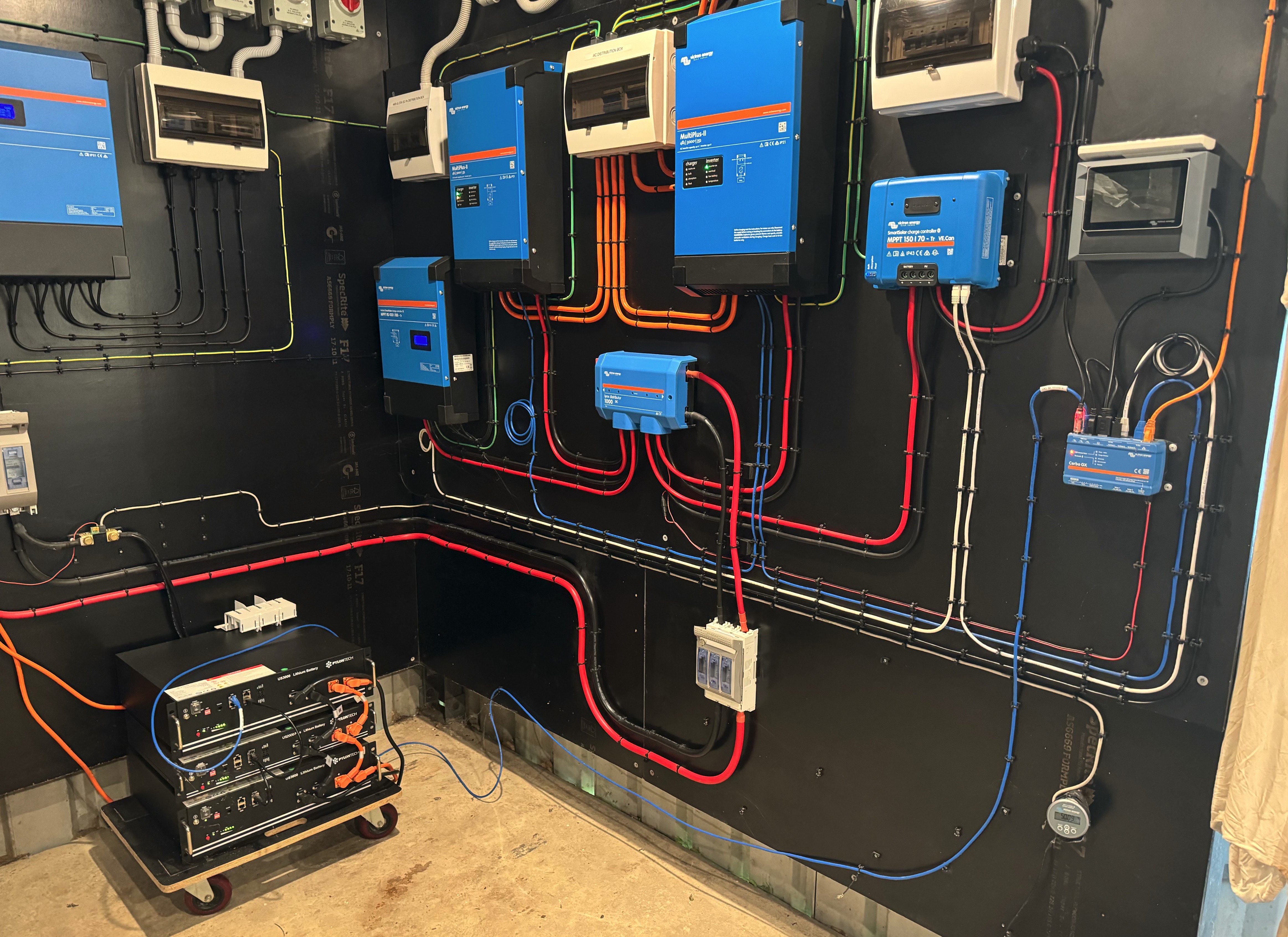
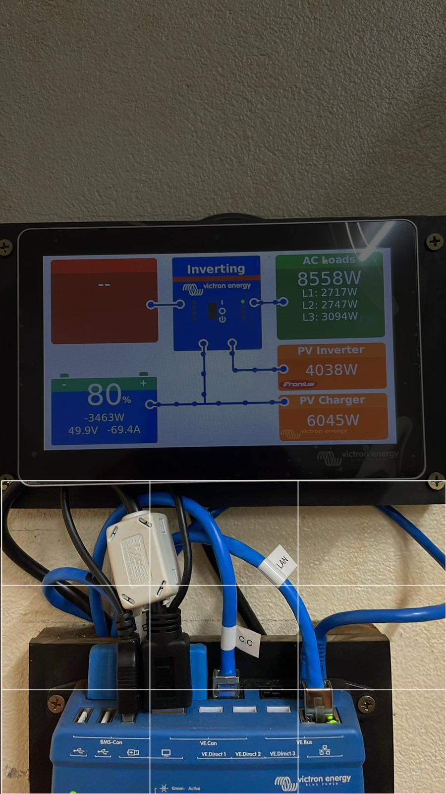
I currently have 3 x multiplus II 10kVa running in parallel for a three-phase system.

The system is connected to 3 x RS450/200, pylontech batteries (~340kWh), 1 x Fronius Eco PV inverter (27kW) which is connected on the AC out side and generator which is connected to AC IN on the multiplus inverters (~80kVa).

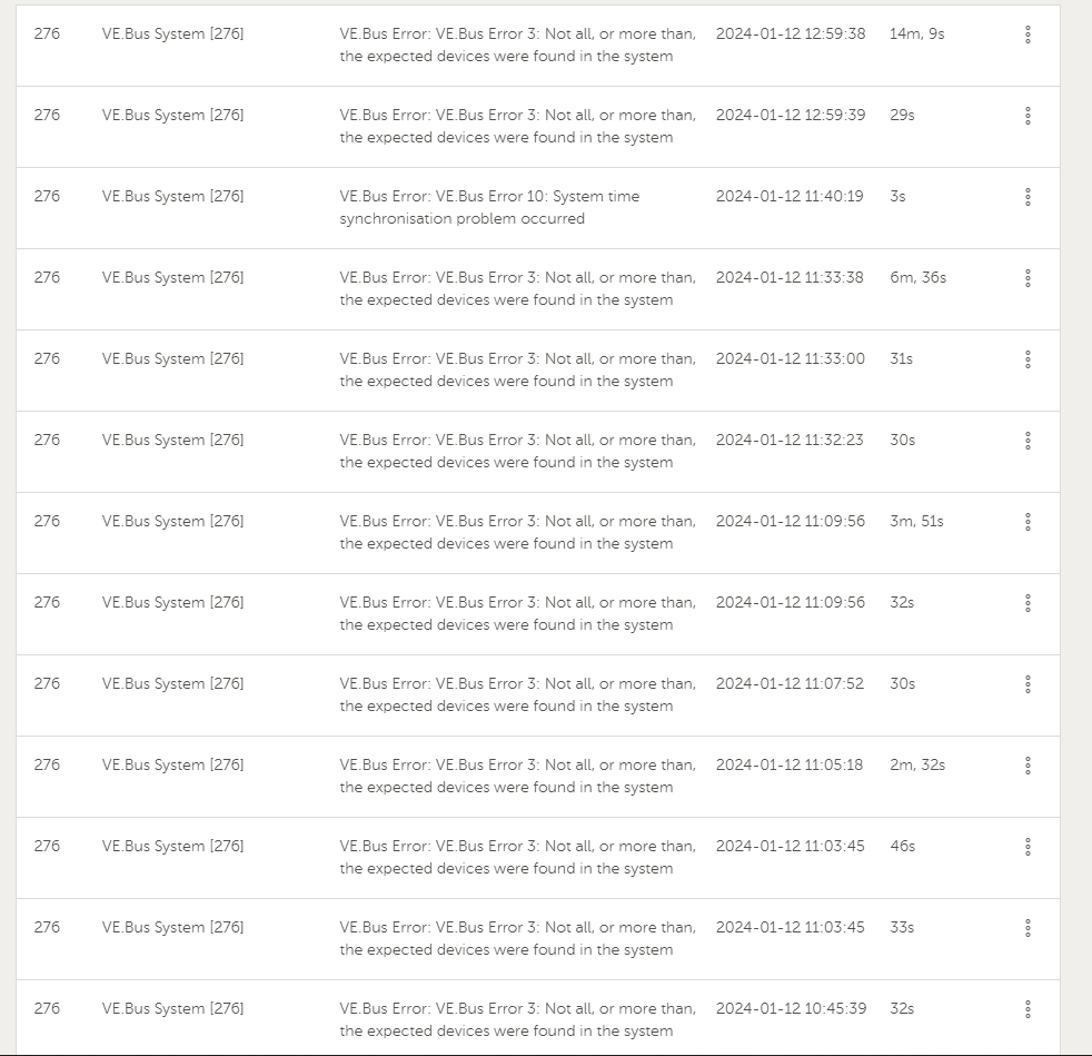
The system seems to work fine without any AC loads connected. Once the load is connected to the system, the system gives Error 3 & Error 10, works for a few minutes than restarts a couple of times before completely shutting down.

Multiplus ii device firmware was updated to v508 - all devices are now up to date with latest firmware.

The MK-3 update (which was giving #51 warning on the VRM console) was updated.

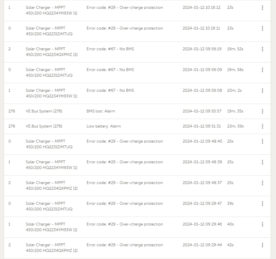
Here are some of the errors from the alarm logs on 12/01/24 when we had tried to run the system:

1705264622785.png

1705264739850.png


This is a newly installed system - Ac cable run is approximately 200m from the inverter/battery room to the generator/ main distribution board room. The PV array is ground mounted with SPDs & 2 pole DC breakers for isolation of each string (isolation boxes mounted on the piles at the array under the panels).

Any advice/help would be much appreciated so I can finally have normal operation of the solar system.

Thanks and much appreciated.

PylontechAC PV CouplingFronius3 phaseerror 3
1705264622785.png (90.5 KiB)
1705264739850.png (75.5 KiB)
2 |3000

Up to 8 attachments (including images) can be used with a maximum of 190.8 MiB each and 286.6 MiB total.

3 Answers
Alexandra avatar image
Alexandra answered ·

@Clay123

This is a fairly complex system to troubleshoot over the forum. I suggest you get more official support from your supplier/dealer.

I assume you have done everything buy the book. Correct wiring sizes, config and setup and programming.

A few notes though. Long AC runs like the one you have can create problems. If it is underground it makes it worse.

Keep the fronius off for now.

Fully charge the system.

Bring a way to load test each phase or all three phases with a slight overload condition with elements or linear loads right there at the installation/ inverters.

Which phase has the issue?

1 comment
2 |3000

Up to 8 attachments (including images) can be used with a maximum of 190.8 MiB each and 286.6 MiB total.

clay123 avatar image clay123 commented ·
Thanks @Alexandra - I will be carrying out load tests tomorrow to see if its a phase problem or maybe a fault within the sub circuits.

As of now, the system doesn't seem to show any alarms or warnings regarding phase faults.

But we might as well try and troubleshoot all possibilities.

0 Likes 0 ·
Guy Stewart (Victron Community Manager) avatar image
Guy Stewart (Victron Community Manager) answered ·

Hi @Clay123,

From my first glance this issue appears to stem from an issue with the communications.

I would double check all communications interfaces, there are many in a system like this.

The Pylontech battery system uses the BMS-Can interface and that needs to be seperate to the VE.Can interface used by the Victron MPPT solar chargers. Both cables look similar, but they need to be kept separated.

Please confirm those two communications interfaces are physically separated on different communication BUSes and correctly configured in the Services Menu of the GX device;

Here are some screenshots of those service menus;

cleanshot-2024-01-15-at-163932.jpg

cleanshot-2024-01-15-at-163939.jpg

cleanshot-2024-01-15-at-163943.jpg


Here is a photo of my example system that shows the separation between the VE.Can cables in white, and the BMS-Can cable in blue to the pylon tech battery.

cleanshot-2024-01-15-at-164323.jpg

If that doesn't help you troubleshoot the issue, please take the same photo of your system (showing those cable layouts), and screenshots of your GX device services menu showing both the VE.Can and BMS-Can ports correctly configured and communicating and I will have a closer look.


6 comments
2 |3000

Up to 8 attachments (including images) can be used with a maximum of 190.8 MiB each and 286.6 MiB total.

clay123 avatar image clay123 commented ·

Thanks @Guy Stewart (Victron Community Manager) for your response.

I can confirm that the cables are physically separated on different VE CAN ports.

Pylontech LV hub - comms connection is using TYPE B cable (VE CAN to CAN-BUS BMS) - One end is from the CAN OUT of the LV hub and the other end is connected at the BMS-CAN port on the cerbo.

Victron MPPT solar chargers - comms connection using UTP cable (RJ45 to VE CAN) - connected at the VE CAN port of the cerbo.

Here are the snips of the services menu:

1.png2.png3.png4.png

I see there are errors on the VE CAN port - could you assist here please ?

6.jpg


This is the cerbo side connection - the cables are labeled (LAN, CC, BATT)


Looking forward to your assistance.


0 Likes 0 ·
1.png (13.0 KiB)
2.png (28.5 KiB)
3.png (30.3 KiB)
4.png (28.0 KiB)
1705316626834.png (1.9 MiB)
Alexandra avatar image Alexandra ♦ clay123 commented ·

@Clay123

For the LV hub side there is a post from perma batteries.

https://community.victronenergy.com/questions/129009/lv-hub-troubleshooting.html

They are a pain when they don't work right.

1 Like 1 ·
clay123 avatar image clay123 Alexandra ♦ commented ·
Hi @Alexandra - yes, the batteries were a bit of a hassle in the beginning trying to get the groups to sync and configured correctly. As of now, the battery groups seem to be working correctly with the correct CCL & DCL readings and number of units online.


Thanks.


0 Likes 0 ·
Hi, I just sent an email.

It might be better to go through the next steps there until we have a conclusion.

1 Like 1 ·
clay123 avatar image clay123 Guy Stewart (Victron Community Manager) ♦♦ commented ·

Noted. I have just replied.


0 Likes 0 ·
clay123 avatar image clay123 Guy Stewart (Victron Community Manager) ♦♦ commented ·

We tried to run the system last night, unfortunately the system kept shutting down. The different scenarios are as follows:

  • system was on and running okay without load, even though the MPPTs were not producing, and the PV Inv was not producing as well.
  • Once load was added, the system had shut down without restarting.
  • We isolated the load again, turned on the system but this time we removed the VE.Bus cable from the Cerbo gx and ran the loads - the system was able to hold for a longer time than the restart time.
  • Once the VE.Bus cable was connected back, the system shuts down
  • Same goes for the VE.Can cable, once removed from the Cerbo gx with load, system shuts down.

Would rebooting the Cerbo help in situations like this?
What would a reboot of the Cerbo do to the system?

Any assistance would be much appreciated.

0 Likes 0 ·
Paul B avatar image
Paul B answered ·

have you got canbus terminators at both ends of the can bus circuits


1705402402716.png


1705402402716.png (20.1 KiB)
1 comment
2 |3000

Up to 8 attachments (including images) can be used with a maximum of 190.8 MiB each and 286.6 MiB total.

clay123 avatar image clay123 commented ·
Yes - I do have terminators at both ends of the can bus circuit
0 Likes 0 ·