question

Dragos avatar image
Dragos asked

3-phase Multiplus II and Fronius Symo ESS config and settings

Hi, Guys.

Please be so kind and help me with some answers related to the following scenario.

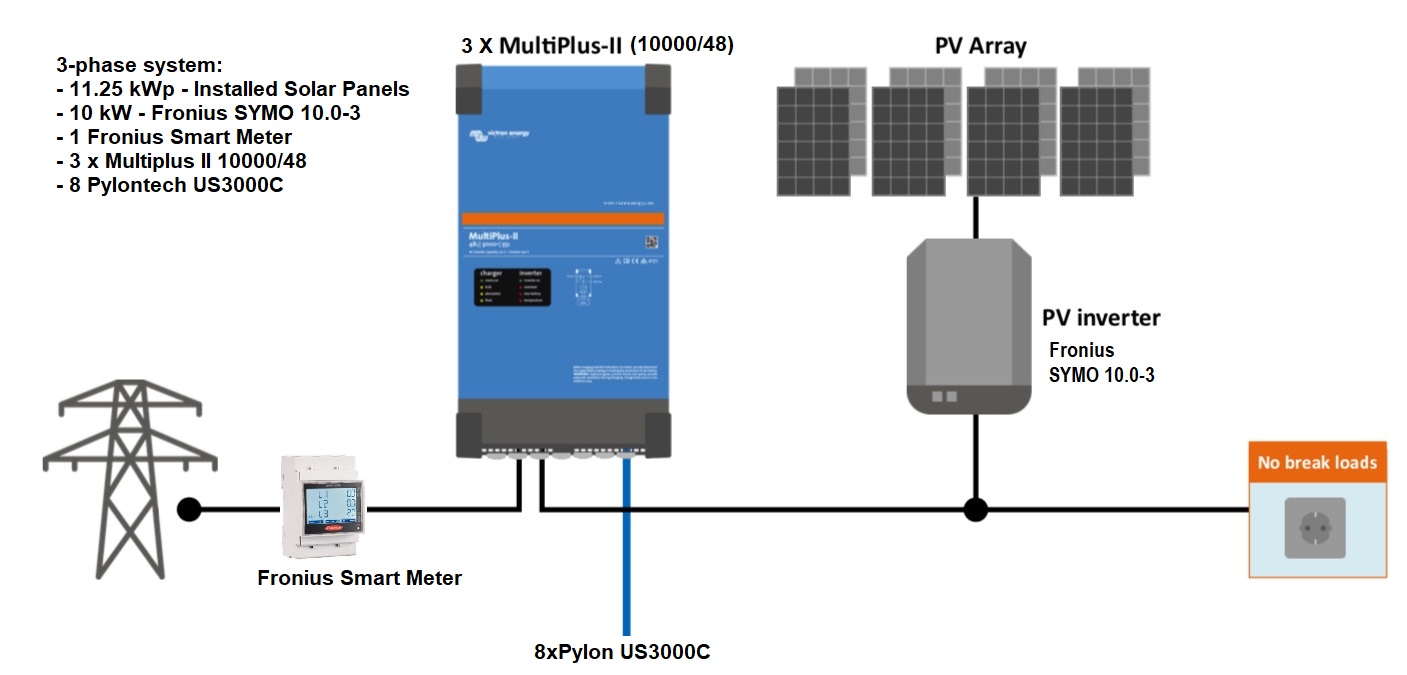
I have a Fronius Symo 10.0-3, Fronius Smart Meter and 30 PV panels already installed and running since more than 18 months. I am both a consumer from the grid and producer (I sell the electricity I produce and do not not consume).

I am about to purchase 3 x Multiplus II 10KVA/48VC and a Cerbo GX device. I also have 8 x Pylontech US3000C batteries. The Fronius inverter will be used on the AC Input and I will always use the critical load output of the Multipluses.

Now, I would like to use the system as following:

- Keep producing electricity with the Fronius and PV panels as much as possible because I get money for kWh

- charge the batteries whenever there is sun or in the worst case scenario from the grid

- use part of the battery energy during the night, let us say 40%-50% and keep the rest for the backup in case of grid failure.

I attached a diagram of how the system will look like.

Would that scenario be possible in ESS configuration?

Is there any other device needed?

Thank you in advance for any ideas, thoughts.


ESS diagram - UND.jpg

PylontechFronius3 phaseess settings
2 |3000

Up to 8 attachments (including images) can be used with a maximum of 190.8 MiB each and 286.6 MiB total.

3 Answers
ponzoa avatar image
ponzoa answered ·

This is possible and a lot more too. You can also connect the Symo on the AC Out so, in case you do have a grid failure the Sympo keeps producing energy, charging the batteries and supplying the loads.


This is called an ESS and you can find a lot of documentation on how to set this up and configure it (and the Symo) on the Victron web and training is available in the professional website.


Good luck!

8 comments
2 |3000

Up to 8 attachments (including images) can be used with a maximum of 190.8 MiB each and 286.6 MiB total.

Dragos avatar image Dragos commented ·
Thanks a lot. I will check.
0 Likes 0 ·
Alexandra avatar image Alexandra ♦ Dragos commented ·
@Dragos
8 Pylontec us3000s are barely enough for1 x 10kva inverter. They will be hurt.

I added some more tags to your post some extra resources for learning more should be linked onto the related resources box on this page.

1 Like 1 ·
ponzoa avatar image ponzoa Alexandra ♦ commented ·
1 x US3000C for 1 x 10KVA is plenty, they'll be fine. I've done this config plenty of times without issues thus far. I'll explain my calcs, in case you see an error I missed;


1 x US3000C provides 37A nominal at 51,2V = 1894.40W

8 x US3000C = 1894.40W x 8 units = 15,155.20W, almost double the 8kW nominal power of the inverter @ 25ºC.

As long as the batteries are cabled appropriately, there will not be any issues.

0 Likes 0 ·
ponzoa avatar image ponzoa ponzoa commented ·
Just to add to my last post - the same kind of calcs need to be considered for 3 x 10KVA inverters. 8 US3000C for 30KVA is a different story and he may end up short and making his equipment suffer whilst shortening it's expected lifespan.
0 Likes 0 ·
Dragos avatar image Dragos ponzoa commented ·
@ponzoa, why do you say the equipment will suffer with such battery capacity? I will be using 3 x Victron 10KW in a 3-phase configuration, because on one phase (on phase L1) I have the heat pump (the only equipment on phase L1) and during the winter period, the pump can draw up to 6KW (at max load). That is why, maybe I oversized the Victron inverters, but I did not want them to run at full load. So, that was my idea. The other two phases are loaded with the rest of the devices/appliances in the house. I appreciate your answers, but for my purpose these battery will do the job or at least this is what I believe. The time will tell. My idea at the beginning was to use the Victron inverters just as an UPS because as I said, from time to time, I have short power outages,, but I purchased the batteries just in case the outage will be longer (2-3-4 hours). Now, I heard and read a little bit about this nice feature which is ESS and I would like to combine this feature with the UPS function, let's say. Otherwise my batteries will be always at 100% and I learned that may be damaged in time if I do not discharge them from time to time. Now, as per your recommendation I would like to install the Fronius inverter on the Victron AC output (critical loads only) and use it as you indicated. But, where should be the Fronius Smart meter left? Will I be able to inject the energy production surplus from the Fronius PV inverter into the grid if the Victron inverters will be between the grid and the PV inverter? This is important because I get paid, not much (about 1/3 of the price I pay for the energy consumed from the grid), but still something. If the grid fails and the batteries a fully charged, who is going to control the Fronius output? Victron inverters? Because in this case Fronius will only produce the energy needed for the loads, maybe.

Thank you.

0 Likes 0 ·
Dragos avatar image Dragos ponzoa commented ·

According to this site: https://www.victronenergy.com/live/ac_coupling:start, for Lithium batteries for "each additional 1.5 kWp of AC PV will require an additional proportional 4.8 kWh increase in battery storage". In my case, I have a 10KW Fronius Inverter, which divided to 1.5 kWp I get a factor of 6.67. 8 x Pylon 3000C, meaning 8 x 3374 Wh (usable capacity) = almost 27 kWh. Now 6.67 x 4.8 Kwh = 32 kWh, so if I purchase 2 more batteries of the same capacity I should be fine. Is this correct? Than kyou

0 Likes 0 ·
Dragos avatar image Dragos Alexandra ♦ commented ·

@Alexandra, thanks for your reply. You may be right with the Pylon capacity, but actually I will never be at 100% load. I have a heat pump which is connected to phase 1 alone and at some point it may need a peak of 5KW. The other 2 phases are somehow balanced with the other house loads. I do not have long period outages, just short ones from time to time, but I only try to reduce the consumption from the grid as much as possible. The total capacity of my Pylontech batteries is about 25KWh, so if I manage to save during one night 10KWh, and recharge them the next day, then I am ok. I did not get you when you said "I added some more tags to your post some extra resources for learning more should be linked onto the related resources box on this page" What did you mean by this phrase? My question was related to the possibility of using this ESS feature as per my drawing I attached in the original post. I got a reply from @ponzoa, but do I need extra devices to make it happen? Can anyone tell me? Thank you.

0 Likes 0 ·
Alexandra avatar image Alexandra ♦ Dragos commented ·

Then consider using smaller inverters.

There are guys who 'get away' with battery banks that are too small for the inverters. The design of the inverters with the transformer needs the battery bank to be able to saturate its core for various reasons.

I can honestly say, if you want a 10year bank do it right. And the batteries are the biggest investment in any system. 2 or 3 years into service the last thing you need is a bank that is developing issues.

The extra resources box if you are on mobile is at the bottom of the page, on laptop/pc is to the right. There are links there for more documents on how to set up the system, with ESS and Pylontec with Fronius. Including how to program and set up.

You could consider a small DC MPPT but then that is not totally necessary since your grid is good.

1 Like 1 ·
Dragos avatar image
Dragos answered ·

ac-couple.jpg (114.6 KiB)
2 |3000

Up to 8 attachments (including images) can be used with a maximum of 190.8 MiB each and 286.6 MiB total.

ponzoa avatar image
ponzoa answered ·

Hi @Dragos , you don't need the Fronius meter for AC Coupled conections. Here is what I think you should do if I understand your intentions correctly - reliability of power supply, export to grid, save money on power bill, monitor.


The grid will connect to the ACIn of the MP's after going through protection. The AC Out of the inverters will go to your distribution board after protection. The Fronius is installed as if in a standard on grid install to the distribution board. In Fronius, activate Modbus TCP and set grid to MG50, no meter. The fronius will communicate with the GX device via Modbus and have production info etc and this will show up in VRM correctly.

In VEConfig, apply the settings as required (you don't need to active the UPS Function as the switch over time in case of a grid failure is less that 20ms. App the ESS assistant and fill in the information in line with your Fronius. The Fronius must be the same or less powerfull that the MP setup.

In the remote console of the GX device, settings, fill in as you normally would but remember;

- Configure ESS Settings in line with your needs. I would suggest in your case Minimum SoC at 40% or 50%. This will allow you to use the rest and reserve that amount in case of a power failure. Remember with AC Coupled, the Fronius keeps working and charging the batteries.

- Grid feed-in: activate "AC Coupled - feed in excess". This will allow you to export the excess power you don't use for consumption and once your batteries are charged again.

- Limit feed-in: activate this and configure the limit if you would be able to export more power than the electrical company allows you to.

- PV Inverters; Set to AC-Out so it knows it is on the output side of the MP's

- MODBUS TCP devices: activate automatic scanning. Ensure both your GX Device and your Fronius is connected to the same network

- Services: Modbus TCP: Enable. You can activate the other MODbus settings also, I always do.


With this you will cover your needs and a little more. I do suggest you add a few more batteries even though your consumption indicates you'll be fine. Once you have VRM running, you'll see your power consumption spikes where it takes power from the grid and the batteries at the same time. This would indicate that in case of a power failure, your batteries won't cover your needs.


Good luck and let us know how you go.


3 comments
2 |3000

Up to 8 attachments (including images) can be used with a maximum of 190.8 MiB each and 286.6 MiB total.

Dragos avatar image Dragos commented ·

Dear @ponzoa,

thank you so much for the reply and nice explanations. Since I have never played with Victron software so far, I do hope everything will go smoothly, thanks to your explanations.

Indeed you, very well, understood my needs and what I want to achieve.

However and I do hope you do not mind, a few more questions came up reading your steps above:

1. I still need to keep the Fronius Meter connected as it is. This will help me compare my meter with the Utility company meter for comparison. Will that affect in any way the functionality you described? In this case do you know if I have to change anything in the grid settings? is it ok to keep it installed between the grid and the MPs?

2. What would be the preferred connection between MP II master - Cerbo GX and Fronius - Cerbo GX? What it be better to use UTP cable or WIFI? I am thinking about the Modbus TCP here.

3. Fronius Symo is capable to generate max 3.33 KWh/phase, so it is way lower than the MP's power for each phase.

4. I cannot export more than 10KWh because that is the maximum output power of the Fronius PV inverter, so we are ok here.

5. What I want to have would be the installation as per the attached drawing.ac_couple.jpg

I will let you know how it goes, hopefully in one month from now, but right now it is only preparation :) and learning from you, guys, who already have experience with such installations. Thank you for that.

Thanks again.

0 Likes 0 ·
ac-couple.jpg (114.6 KiB)
ponzoa avatar image ponzoa Dragos commented ·

Happy to help.


1. The MPs have internal meters. If everything is running through the MPs, you don't need the meter, you have it in VRM. If you do want a meter, get one that works with Victron. That way, if you add extra solar through DC Coupling (for example), you'll be able to meaasure that too. The MPs sync with the grid so there is always an inport or export, even if it's just 10W,-50W, or whatever. I strongly suggest against the Fronius meter in this case also because of grid failures give you strange readings and undo your data.


2. A network cable to a switch connecting the Cerbo GX and the Fronius and connecting this switch to your router. The MP uses a Cat5 cable to a different port of the Cerbo.


3. Perfect, won't be a problem. Just stay under 30kW in AC Coupling if you decide to add more Fronius inverters. If you go DC Coupling, you have no limit.


4. OK. I am referring to the power supply you have contracted. In many countries, your grid conenction power is limited by what you have contracted or the physical connection. This limit is based on this. As you won't export more than you produce, and you won't produce much, you can leave the limit setting at off.


5. No problem, just remove the Fronius meter.


A good idea, especially for someone new at this, would be to install a by-pass. That is, a switch which let's you select if the power from the grid goes direct to the switch board, or through the MPs. This way, your house still has power while you set everything up, cable, config, test, etc. Also, if you have issues or need to do maintenance, your house can have power there too.


Good luck and enjoy the learning curve.

0 Likes 0 ·
Dragos avatar image Dragos ponzoa commented ·
Dear @ponzoa,

thanks a lot. It is clear for me now. I will remove the Fronius meter and do the configs in the Fronius as indicated by you. I checked yesterday evening and indeed there is a Modbus section in the menu where it is set to Off now (for export). I will set it to TCP and set the grid to MG50.

Appreciate your help. thank you so much.

All the best.

I will send you an update after the installation.

Have a great day!

1 Like 1 ·