question

cbnw avatar image
cbnw asked

OPTIMAL VE.Can Wiring configuration for Cerbo GX, Wakespeed WS500 & Maretron N2K View.

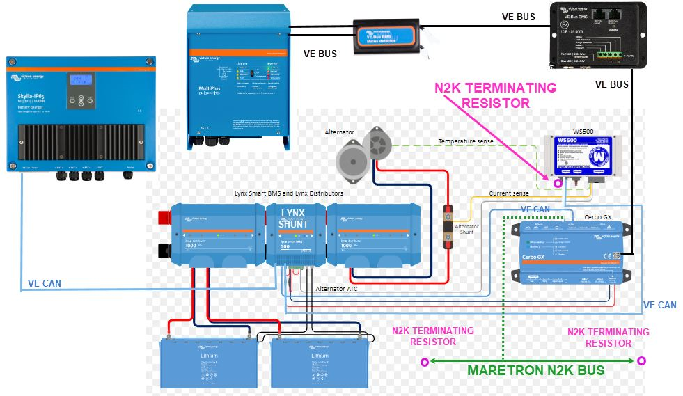
Objective = Identify Optimal Ve CAN / Ve Bus cabling config to 'converge' an EXISTING Victron ecosystem (that includes a Wakespeed WS5000) with an EXISTING Maretron N2K CAN Bus (20 devices).

See image below for current config.

  • Image below includes a "PROPOSED' dashed green line to connect the existing Victron/Wakespeed ecosystem to the existing Maretron N2K CAN Bus.


  • I am hoping an experienced Victron technician who has implemented a similar design can advise on this and answer questions below. (Thank you in advance - this is my first Victron project.)victron-ws500-n2k-draft1png.png

Questions

1. Is 'PROPOSED' config in image above optimal - or does it violate any Victron cabling requirements ?

2. If it does violate the Victron requirements, adding Ve CAN cable drops from each victron device to the EXISTING Maretron N2K CAN Bus would be the optimal configuration?

3. Either way, we leave all the Ve Bus cabling config in tact - correct ?

4. Is it optimal to leave the WS5000 connected to Lynx Shunt 1000 (Ve CAN) per diagram below ?

5. Does the Victron Ve CAN design allow you to 'daisy chain' a Cerbo GX, SKYLLA IP-65 CHARGER & Multiplus 12/3000/120-50 120v together on their Ve CAN ports AND THEN connect to a 3rd party N2K bus via the Cerbo's 2nd Ve CAN port?

- This 'daisy chain' config in #5 above, assumes the Cerbo is designed to aggregate all the Ve CAN data & serves as a 'bridge/gateway's to the 3rd party N2K bus ?

(Per the Victron "NMEA 2000 & MFD integration guide" = 2.1 Systems with a GX Device, it acts as a hub, collecting information from connected equipment, such as Inverters, Battery Monitors and Chargers; and then making them available to a MFD & N2K network at the same time).

( ** Either way we modify this project I'm aware that 12V DC power must be disabled on victron drops & final converged CAN bus can only have 2 terminating resistors, therefore one of the 3 located on the vessel will have to be removed. ** )

Victron

  • Lynx Shunt 1000
  • Cerbo GX
  • Multiplus 12/3000/120-50 120v
  • SKYLLA IP-65 CHARGER
  • Ve bus mains detector
  • Ve Bus BMS

WAKESPEED

  • WS5000 (1 terminating resistor connected & connected to Lynx Shunt 1000 Ve CAN port #2)

Maretron N2K bus

  • Approximately 20 nodes
  • Two terminating resistors


cerbo gxVE.Canlynx shuntNMEA 2000 - N2K
2 |3000

Up to 8 attachments (including images) can be used with a maximum of 190.8 MiB each and 286.6 MiB total.

2 Answers
Paul B avatar image
Paul B answered ·

Note you must only have two terminating resistors in a can bus system ,

A backbone needs one resistor at the start and ends, any spurs going off the backbone do not require termination resistors.


so you have a resistor at the wake speed there should be another one at the skyla unit as this is the last in the string. if you want to then connect this to the maretron system, then you should use a can bus bridge to do this,


the way you have suggested will cause canbus errors


Item 2 would work by droping each unit as a spur, in therory each spur can have a max of 3 units on the spur one after the other, but its not recommended by the Can Bus specs, (Should work ok though) max power usage on the bus must be considered as wll


item 3 yes do not connect can bus to any ve bus systems


item 5 its not victron that advises re daisy chaining its the canbus standards, if you deviate from the canbus standards then the canbus network may become unstable,

2 |3000

Up to 8 attachments (including images) can be used with a maximum of 190.8 MiB each and 286.6 MiB total.

cbnw avatar image
cbnw answered ·

Paul - Thanks for the info.

A few questions for you:

1) I'm from the "Maretron" world (maritime) where we use the terms 'backbone' (bus) and "drops" (devices w/6 meter max drop cable to the bus). See Maretron N2K image below ("N2K" is the "VE. CAN" equivilant in maritime).

- When you say "Spur" , is that the equivelant to a drop? Or does Victron define "spur" differently.


2) From the Cerbo manual ("140558-CCGX", page 13 / section 4.5 ) - Victron states you can "string victron devices together along this bus".

- Is Victron trying to convey the same "backbone / drop" concept of Maretron N2K?

* OR *

are they saying the following VE.Can cable config is approved "CERBO --> SKYLA IP-65 CHARGER --> LYNX VE.CAN SHUT.


Thanks !

cerbo-page-13-string.png


maretron-n2k-bus.jpg


2 |3000

Up to 8 attachments (including images) can be used with a maximum of 190.8 MiB each and 286.6 MiB total.

Related Resources

Additional resources still need to be added for this topic

Cerbo GX product page

GX family product range

Cerbo GX & GX Touch datasheet

Cerbo GX Manual

Venus root access document

Lynx Shunt VE Can online manual


Additional resources still need to be added for this topic