question

bradley-thompson avatar image
bradley-thompson asked

Using Smart Shunt as DC Load meter - VRM is not mapping correctly

Hello,

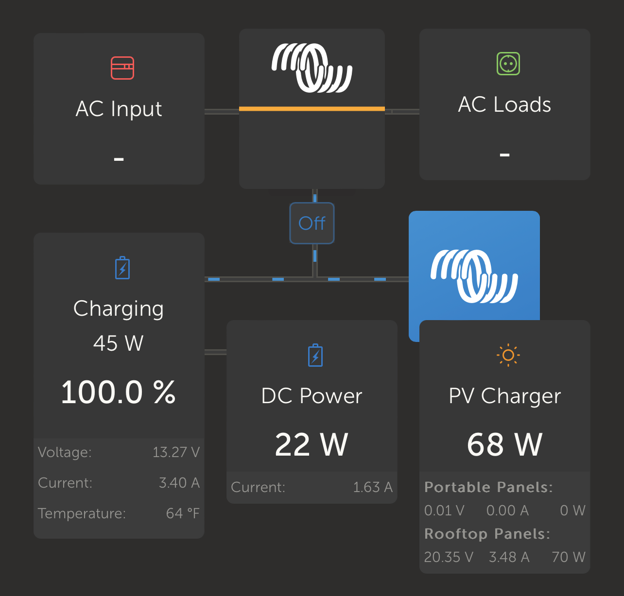
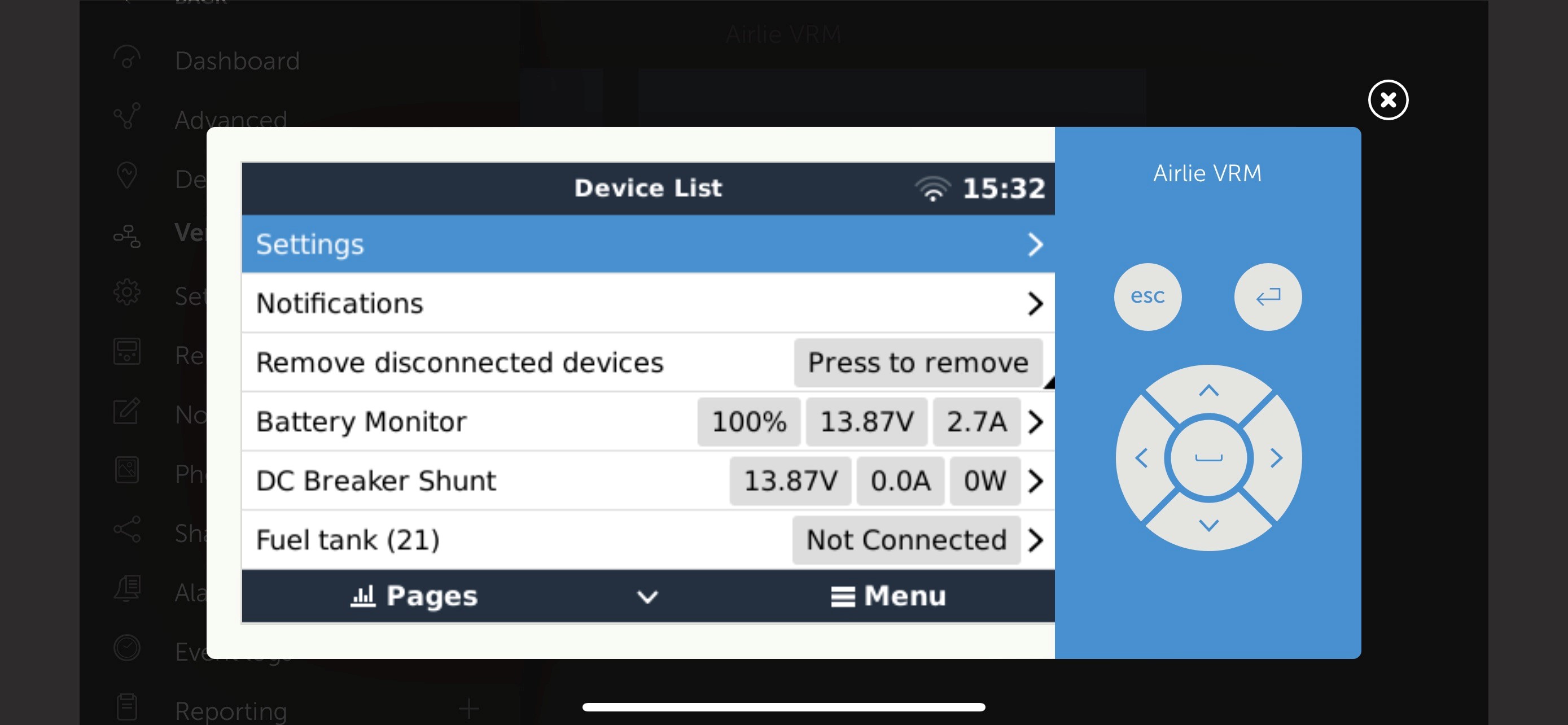
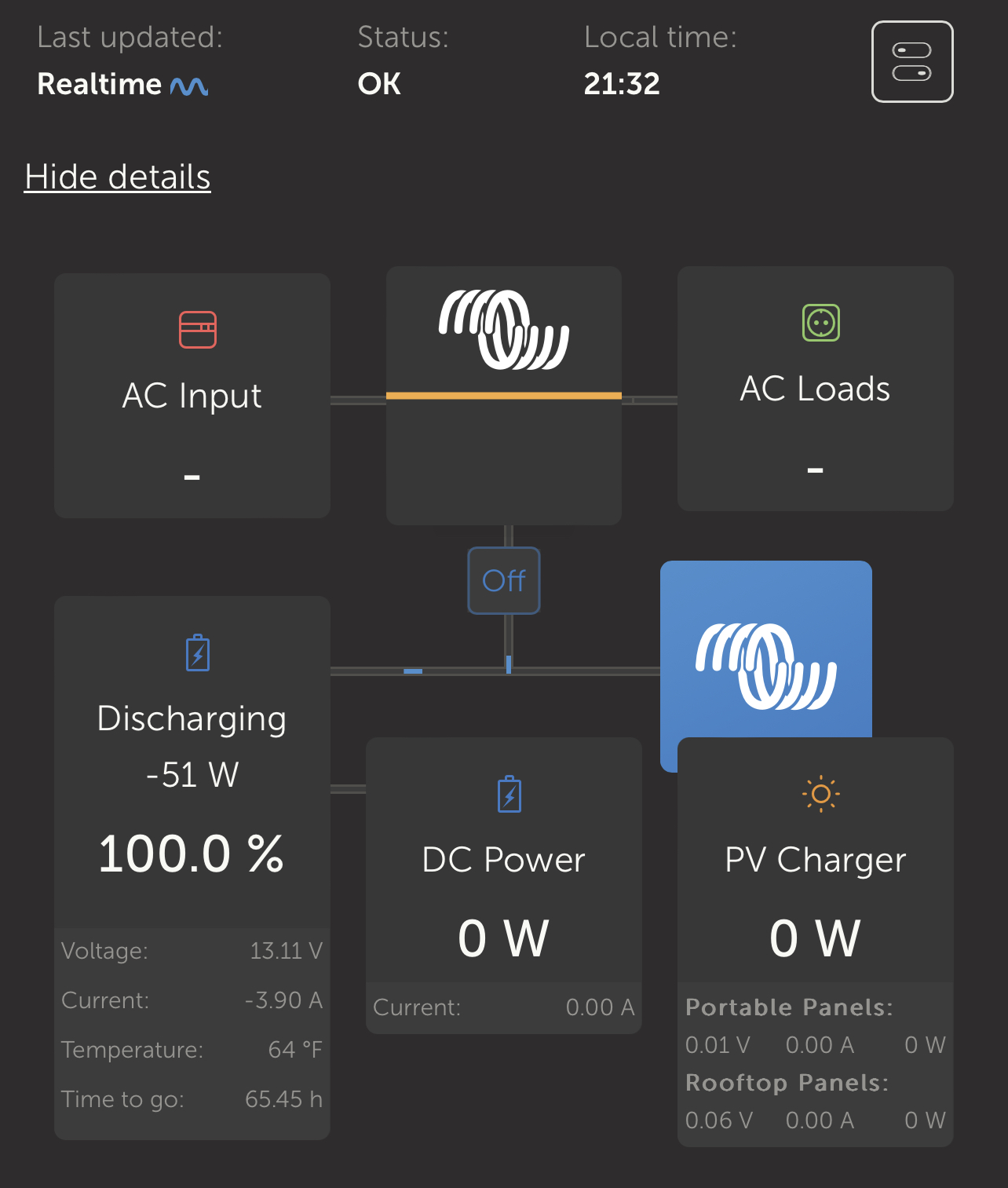
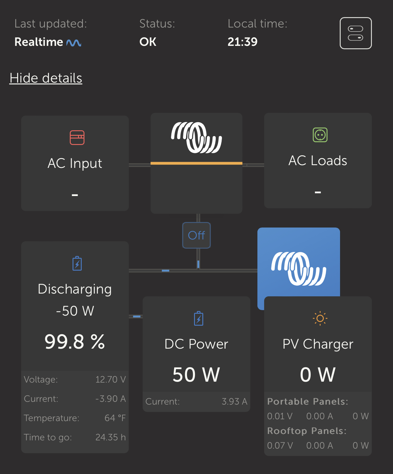
I have setup a Smart Shunt as a DC Load meter in my RV setup. I basically want the Smart Shunt to report the current being used by the DC loads in the RV so that the MPPTs can compensate for it when they are charging the batteries. However, it doesn't seem to be working/reporting correctly. For instance, when I turn on DC loads (lights in this case), the amperage is reported in VRM as going to the general system, not DC loads (note in last picture that the DC meter reads 0.0 amps being used but 22-28w seem to be outflowing constantly). Is VRM working correctly?

Some details:

* Smart Shunt is configured as DC Meter (currently specified as General Loads in misc. settings)

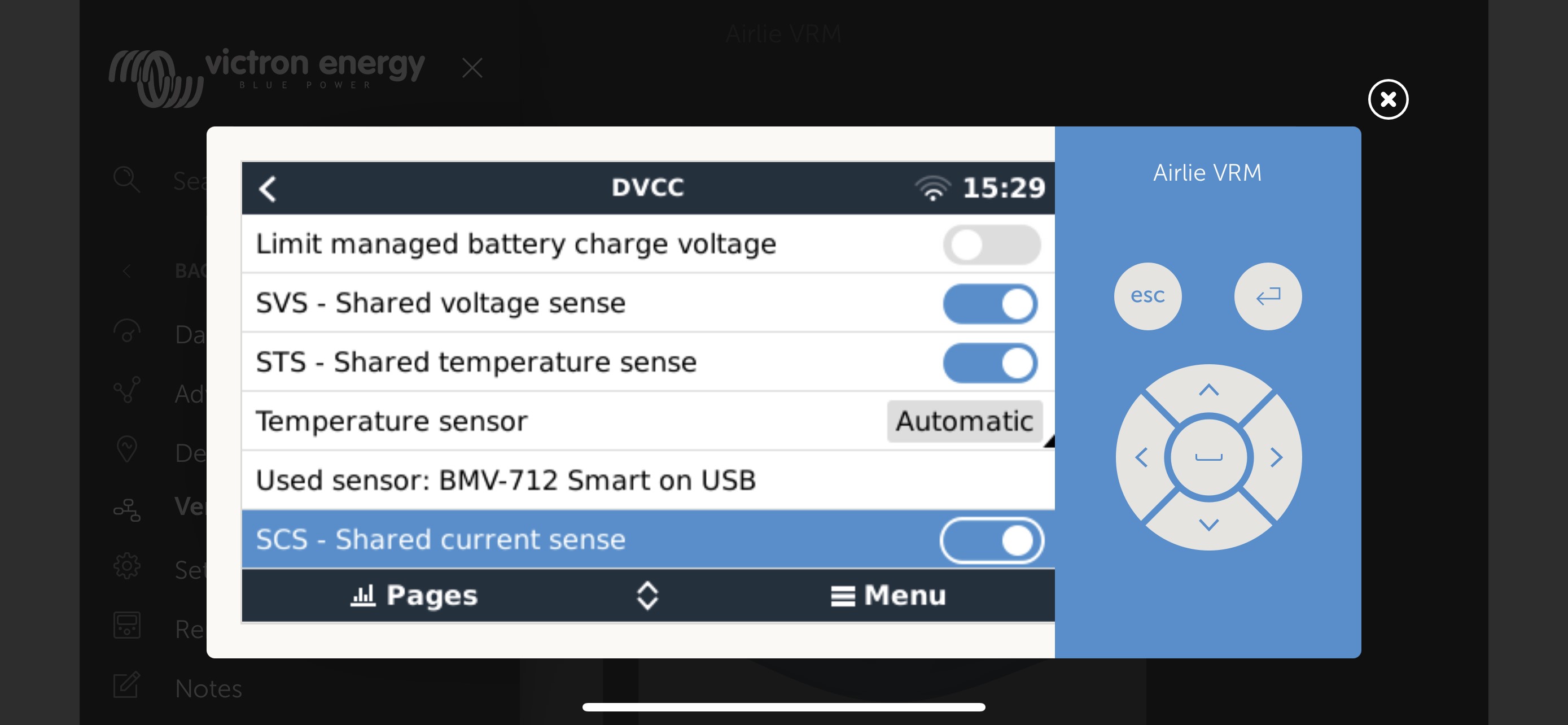
* I'm using DVCC - SVS, SCS enabled.

* I have no way of tracking current in AC loads/sources in the VRM system - I'm looking to add at least another Smart Shunt on my inverter if I can get this working correctly.

* I have the "Has DC System" setting enabled in my GX unit (a Raspberry Pi running VenusOS Large in my case).

* I can see the DC System in the main VRM screen.

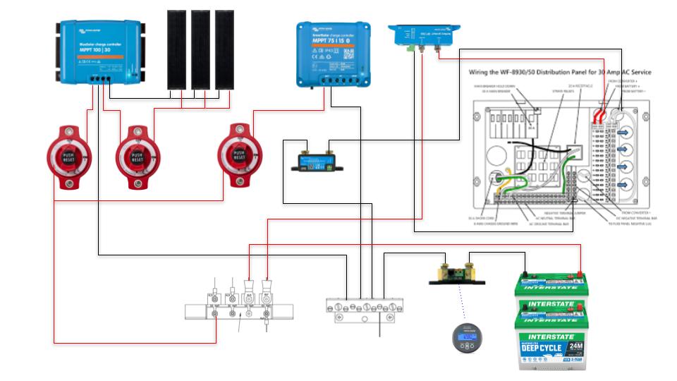
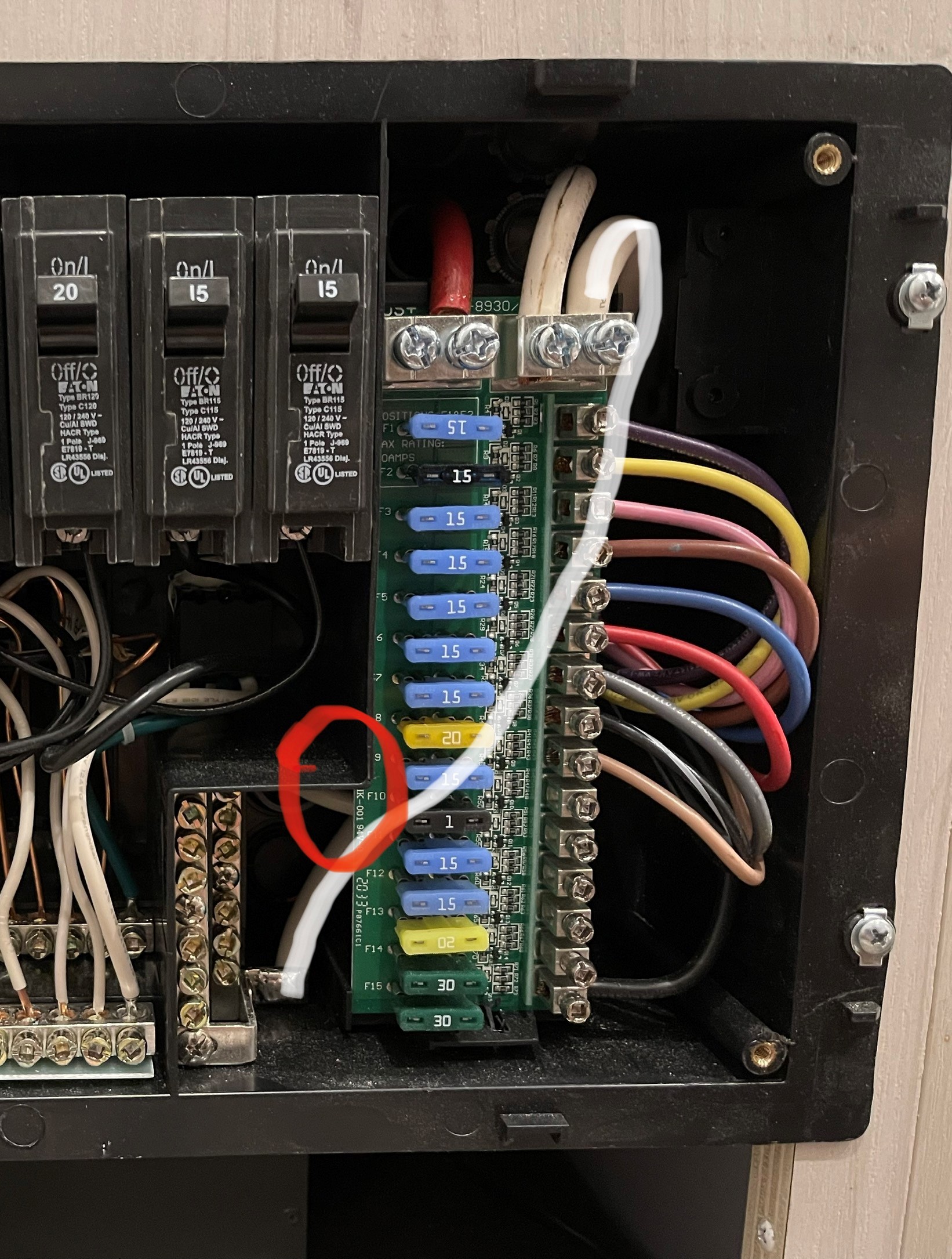
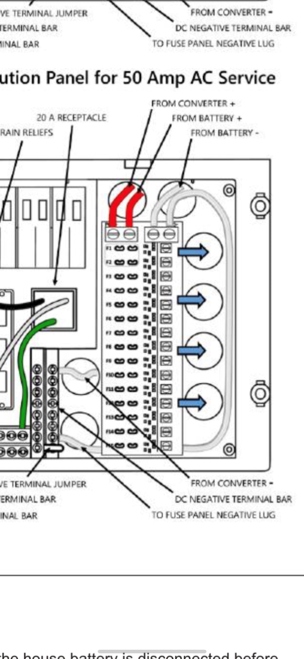
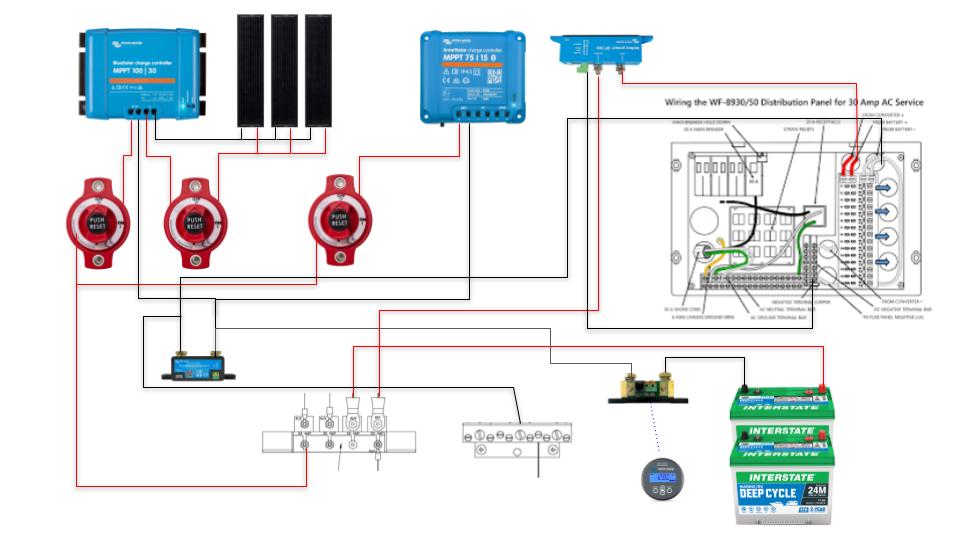
System configuration:

airlie-install.jpg

airlie-vrm.png

dvcc-settings.jpg

vrm.jpg

SmartShuntdc system
airlie-install.jpg (60.4 KiB)
airlie-vrm.png (158.1 KiB)
dvcc-settings.jpg (229.1 KiB)
vrm.jpg (234.3 KiB)
8 comments
2 |3000

Up to 8 attachments (including images) can be used with a maximum of 190.8 MiB each and 286.6 MiB total.

bostonmarinervelectrical avatar image bostonmarinervelectrical commented ·
Looks ok to me. You batteries are being charged (from solar) at 3.4amps so that value shows positive in the battery box. You are outputting 1.63amps to the dc system (also positive). If you were drawing more amps than you were producing, your battery would show a negative amp value.


Both boxes are setup to show amps in to the box = positive. You will always have some current flow to power the system.

Someone correct me if im wrong.

0 Likes 0 ·
bradley-thompson avatar image bradley-thompson bostonmarinervelectrical commented ·
Notice how in the last picture the shunt reads 0 amps? I could turn on all the lights which would cause a 50w load on the DC system and the shunt will still show 0 amps. My concern is that while the VRM mapping seems OK that the current isn’t being reported through DVCC to the MPPT so it can compensate. At nearly 100% charge, I won’t see huge current inflow to the battery right now so hard to know if it’s accurate. FWIW, the charger/converter is connected directly to the 12v panel so it’s hard to separate it from the system. My initial concern was that DC was draining somehow through the charger but disconnecting the + lead from the panel made no difference.
0 Likes 0 ·
bostonmarinervelectrical avatar image bostonmarinervelectrical bradley-thompson commented ·

Where is the negative of the charger connected? Also if you have a clamp meter you can measure amperage before and after the shunt and see if theres actually current flowing.

0 Likes 0 ·
bradley-thompson avatar image bradley-thompson bostonmarinervelectrical commented ·

The negative of the charger is connected to one of the negative buses in the breaker panel. I tried disconnecting the positive side of the charger (while the charger remained off) but the results were the same.

EDIT: here is a picture of the panel. The white line ties the DC negative bus to the fuse panel - its also soldered in. The red circle is the charger wire coming in - I'm assuming its connected to the negative bus but can't recall exactly where. As soon as I get home, I'll take a look and see.

breaker-panel.jpg

The manual to the WFCO breaker box is below - it appears to be wired correctly. Note that the second red positive wire missing from my breaker panel is actually on the battery side of a Smart Battery Protect which is mounted behind the panel in the compartment. There is also a relay/solenoid that acts as a manual battery disconnect. I could use the SBP for this but didn't feel like running new wires. The negative for the SBP is connected to the negative bus bar here - I don't think that could be the issue (?). The solenoid does have an LED lit 3-way momentary switch which is powered off of two fuses mounted to the solenoid. A little confusing. I don't know where the negatives to those fuses end up but the positive connections are from the battery + studs on the solenoid.

wfco-manual.jpg


0 Likes 0 ·
breaker-panel.jpg (796.2 KiB)
wfco-manual.jpg (388.7 KiB)
bradley-thompson avatar image bradley-thompson bostonmarinervelectrical commented ·

I don't have a clamp meter (yet). I think I may disconnect the negative lead from the charger and see what happens. It has to be that the DC is draining through either the charger or the chassis. I assume that the charger is grounded through the AC connection and maybe the DC portion of the circuit is grounded there too? If that is the case, I have no idea how to correct it without running a new wire all the way from the DC panel to the negative bus near the battery compartment. At that point, I would just assume run romex and install a new Victron Phoenix charger near the battery box.

0 Likes 0 ·
pwfarnell avatar image pwfarnell commented ·
Have you got the connections on the shunt the right way round.


Is the shunt measuring all the DC loads, if so you could set it as the "DC system" rather than general loads then the Smartshunt will populate the DC system box. Ignore this if you have other DC loads.

0 Likes 0 ·
bradley-thompson avatar image bradley-thompson pwfarnell commented ·
I verified the connections but will check one more time. I’ve tried the “DC Loads” setting and the result was the same. Will try again and report back.
0 Likes 0 ·
bradley-thompson avatar image bradley-thompson bradley-thompson commented ·

Double checked the connections and it appears to be wired correctly.

Here is another example: it’s dark so the MPPTs are off and I disconnected shore power.


cc4eb2ef-eeea-4e61-8e0f-af80b89a51f2.jpeg

The system seems to think it’s discharging to one of the AC circuits. I actually changed the setting to “DC System” for this reading.


Oddly enough, when I switch it back to “Generic Load”, I get this:

0 Likes 0 ·
2 Answers
bradley-thompson avatar image
bradley-thompson answered ·

Well, I figured it out. I noticed that none of the negatives from the loads were feeding back into the 12v DC panel. Turns out there are three (or more) wiring harnesses that feed into the negative bus that are otherwise unlabeled. I moved some leads around and moved the battery connection to the DC shunt and everything works now as expected. Updating my drawing for anyone else who might be trying to wire this into a WFCO box.

airlie-install-1.jpg


2 |3000

Up to 8 attachments (including images) can be used with a maximum of 190.8 MiB each and 286.6 MiB total.

michaeld avatar image
michaeld answered ·

If you have "has DC system" selected but no shunts configured as "DC system", the DC box will be calculated as the difference between what the inverter is using, what the MPPT is generating and what the battery sees. So if you have any shunts set to "generic load", "DC source", "DC load" etc these will be ignored and it will show the estimate.

If you have one or more shunts configured as "DC system", the DC box will be the sum of those shunts only - it will not estimate as above. So you should only set a shunt as "DC system" if there's absolutely nothing else (excluding inverters and MPPTs) that's bypassing that shunt. Perhaps there's a chassis ground somewhere?

2 |3000

Up to 8 attachments (including images) can be used with a maximum of 190.8 MiB each and 286.6 MiB total.

Related Resources