question

jbakuwel avatar image
jbakuwel asked

Victron MP-II and 4 * Pylontech US5000: cable sizing question

Hi all,

The Pylontech battery modules have been supplied with 25mm2 interconnects and 2 * 2m 25mm2 battery cables. The MP installation manual however states at least 70mm2 is required.

The Pylontech documentation states max. continuous Charge/Discharge Current (A) of 100A (recommended 80A) which these 25mm2 cables - apparently - can handle. The Victron documentation for Pylontech, if I'm reading it correctly, seems to suggest implicitly that the standard/supplied 25mm2 interconnects (and presumably 2m battery cables) are suitable.

This system will have a RS450/100 and PV inverter installed (with similarly sized arrays on both). I intend to limit the charge amps for both MultiPlus and RS450/100 to 50A ea, ie. limiting the max charge current to 100A and perhaps set the total max charge current to 100A in DVCC on the Venus GX as well even though I suspect 4 parallel US5000 could handle more (but not the Pylontech supplied cables). Can someone offer some insights whether the standard Pylontech 25mm2 cables are adequate when total charge/discharge currents are limited to max 100A and fused with 160A?

I've read a couple of posts here on the forum and while the Pylontech cables (apparently) are rated for higher currents (even though they are only 25mm2), I do sense not everyone agrees these are suitable cables.

For easy ref:

https://community.victronenergy.com/questions/41642/pylontech-battery-cable-spec.html https://community.victronenergy.com/questions/30915/pylontech-cable-size.html https://community.victronenergy.com/questions/148564/multiplus-2-485000-with-pylontech-us5000.html https://community.victronenergy.com/questions/161522/multiplus-ii-with-pylontech-stack-cable-and-fuse-c.html https://www.victronenergy.com/live/battery_compatibility:pylontech_phantom

Kind regards,

Jan

Multiplus-IIPylontechrs450
2 |3000

Up to 8 attachments (including images) can be used with a maximum of 190.8 MiB each and 286.6 MiB total.

5 Answers
Alexandra avatar image
Alexandra answered ·

@jbakuwel

They get warm. Warm cables = inefficient and energy losses. The insulation on them is rated for higher operating temps, but I can honestly say you wont like it.

Bus bar them as individuals (or in a pinch in 2 pairs), then run your MP cable and mppt to it. Daisy chaining (while supported by Pylon) is a rubbish way of connecting a bank up. We have done extensive experiments and have seen some issues.

2m from the inverter means you need to up rate your inverter cable size now as well.

Keep DC runs as short as possible especially on the discharge side.

4 comments
2 |3000

Up to 8 attachments (including images) can be used with a maximum of 190.8 MiB each and 286.6 MiB total.

johnone avatar image johnone commented ·
Hi @Alexandra, comments on the below thermal photo welcome. Is 9C above thermal what you'd expect? What do you see with the busbar method?
0 Likes 0 ·
Alexandra avatar image Alexandra ♦ johnone commented ·

@Johnone

Yeah. Nice picture.

For me its also the current sharing, which you can also see in the picture.

Hotter on the outer units, cooler on the inner ones. Who is getting the current first and working harder? Points of resistance usually the terminals.

I have seen the end ones on stacks fail more often than other ones as well.

With the bus bar method, the warmer ones are usually the terminals of the battery and where the lugs are. Cable is maybe one or two degrees up. It depends how many batteries and how much current you are hitting them with.

0 Likes 0 ·
johnone avatar image johnone Alexandra ♦ commented ·

Hi @Alexandra, I'm still trying to read the picture - it's important to me as I'd like to maximise battery life!

Looking at the short -ve link cables on the left from the top battery to the bottom and then the 2m feed to a Lynx, the three link cables look to be getting progressively warmer, as they are carrying more and more current (and vice versa for the +ve links from bottom to top). Does the picture thus indicate that the 4 batteries are properly sharing the load?

I'm assuming the BMS is managing the sharing, i.e. the BMS knows there's 4 batteries, what the total load is and expects there to be 3x 25mm link cables (with a given 'resistance', given ambient temp, length and load), factors in the cabling and then asks each battery for the calculated, shared load - is that wishful thinking and the BMS isn't that clever?

0 Likes 0 ·
Alexandra avatar image Alexandra ♦ johnone commented ·
@Johnone

Take a tong tester/amp tester you will see they do not current share well like that, as evidenced by the colder cables the further away from the connected terminals. Less heat = less amps being processed.

There are a couple of resources out there for you to read why and see in practice.

Off the top of my head there is s video by David Poz on you tube, where he explores daisy chaining and measures on video the current share. I think he uses SOK? or some other brand but has shunts measuring as well.

Wiring unlimited does the basic theory as to why it behaves like that.

Daisy chaining is not always bad (and it officially supported by them). On much larger (not minimal banks) it is ok also depends on the set up. But I have seen in home set ups most people buy the minimum needed (or less) so each needs to be able to pull its weight equally, so to speak in this case the individual bus bar works best. On pylons it is usually the end two that end up having issues or at least it has been from what i have seen.

0 Likes 0 ·
jbakuwel avatar image
jbakuwel answered ·

@Alexandra thanks for the superfast reply :-)

Are you suggesting to parallel the battery modules using additional prefab standard Pylontech 2 meter 25mm2 cables? The additional benefit would be that it allows me to add fuses for each battery, something I hope but am not at all sure is also built into each battery module.

3 comments
2 |3000

Up to 8 attachments (including images) can be used with a maximum of 190.8 MiB each and 286.6 MiB total.

Alexandra avatar image Alexandra ♦ commented ·
@jbakuwel

If you want individual fusing then the lynx distributor is perfect for that. Their cables are quite nice, just not for daisy chained if you want efficiency.

0 Likes 0 ·
jbakuwel avatar image jbakuwel Alexandra ♦ commented ·
@Alexandra Until now I've build battery banks from individual cells, first time experience with Pylontech. Thanks for the tip re Lynx distributor. Pity that the Lynx distributor can't talk directly to a Venus device; adding either a Lynx Shunt VE.Can or Lynx Smart BMS in this case can't be economically justified. Being able to detect a blown fuse (other than via a LED) is very nice though.
0 Likes 0 ·
Alexandra avatar image Alexandra ♦ jbakuwel commented ·
@jbakuwel

There is a hack for it to loght lights. There is also one to modify the power in to take fuses. Just take a look around.

But in all honesty a fuse blowing (should be) a rare occurrence.

0 Likes 0 ·
johnone avatar image
johnone answered ·

Not saying this is the correct way to do it, just providing a thermal photo which shows what happens when you connect them as per the manual. They are 4x 3000C in a cupboard in the kitchen, using the supplied 25mm cable. The photo is taken during an overnight cheap tariff charge, thus around 70A, which could take 2-3 hours (charged by a MP-II 48/5000/70-50, which is the other side of the wall, in the garage). 4x3000c-chraging.jpg
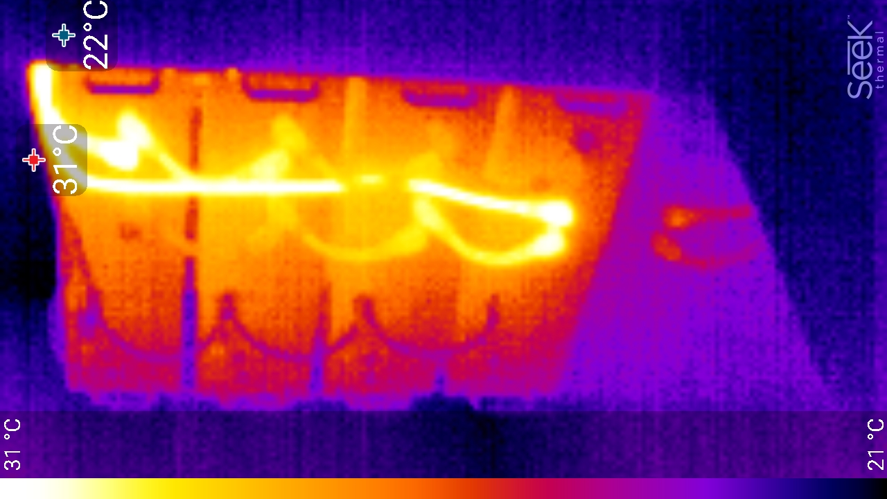
Presumably, given the cable temp (31C or 9C above ambient) and the time period you could work out what the losses are and if you want to upgrade. For the 5000, it would seem likely you'd need 2x sets of 2m cables.


4x3000c-chraging.jpg (375.9 KiB)
2 |3000

Up to 8 attachments (including images) can be used with a maximum of 190.8 MiB each and 286.6 MiB total.

jbakuwel avatar image
jbakuwel answered ·

@Alexandra @Johnone Thanks for the replies and photo, much appreciated. It looks like 4 * 2m 25mm2 cables (shortened to the same length if the installation allows that) with fuses for each module is the better way to do this.

5 comments
2 |3000

Up to 8 attachments (including images) can be used with a maximum of 190.8 MiB each and 286.6 MiB total.

kevgermany avatar image kevgermany ♦♦ commented ·
I'm building a similar system. Same batteries, 5K inverter/charger plus solar. Max current through the batteries about 320A. Batteries will go to a lynx power in. In parallel. Power in goes to a lynx distributor for fuses and charging/loads. Standard pylontech cables to the power in. Charging and loads to the distributor. Heavy gauge cables to the distributor as appropriate.

Not built yet, so no feedback for you based on experience. But I did consult @Alexandra first, she really knows her stuff.

0 Likes 0 ·
jbakuwel avatar image jbakuwel kevgermany ♦♦ commented ·
By wiring the modules individually to a busbar at least the cabling will more suitable for higher currents. Not sure how much the Pylontech BMS will accept though; we'll find out :-)
0 Likes 0 ·
kevgermany avatar image kevgermany ♦♦ jbakuwel commented ·
Each battery has its own BMS, so 100A per battery sustained.
0 Likes 0 ·
johnone avatar image johnone kevgermany ♦♦ commented ·

Hi, a question re 320A. I see the manual says 'recommended charge/discharge current' = 80A for one US5000, and 4x80 = 320. But then there's system current and a 5kVA inverter/charger (MP or Quattro) has e.g. in the Quattro spec: 'Charge current house battery' = 70A @ 57.6 V DC. Of course, you could have a big solar array which could harvest 320A @ 50V plus, but it would seem oversized and would charge 4X 4.8kWh batteries in just over an hour.

Is there a distinction to be made between individual battery spec and system spec, and it's system spec which determines cable size?

0 Likes 0 ·
kevgermany avatar image kevgermany ♦♦ johnone commented ·

80A is the recommended max continuous, but they also say 100A is the max continuous.

It's easier if you think of the system design and the loads of its sections.

Cable size is determined by the current and cable length in each section of the circuit. So 100A cables between each battery and Lynx, but much fatter ones on the heavier loaded areas. I'm going to be driving an electric motor of 13kW. Most of the time it will be running at a much lower output, but cables have to be sized for the top end. So Lynx to motor controller sized for 300A, Lynx to multi will be sized for 70A, solar to Lynx 15A etc.

Battery spec really depends on system requirements... Max current, how long it has to survive when not being charged, or receiving less charge than load. Also battery type as this determines usable capacity.

So you start with objectives/performance to be met and design from there.

.

0 Likes 0 ·
Jason - UK avatar image
Jason - UK answered ·

@jbakuwel as an example, I had 2mtr of 35mm2 cable between my 5kva Multiplus and my 20kWh worth of battery storage. When I was continuously pulling 4.4kW from the inverter, the positive became too hot to touch after a hour. Now I have 70mm2 cables, the most they get is slightly warm. The other issue was the noticeable volt drop between the batteries and the inverter, 4 volt drop at times whereas now its less than 0.5v drop.

2 |3000

Up to 8 attachments (including images) can be used with a maximum of 190.8 MiB each and 286.6 MiB total.