question

kennybuntinx avatar image
kennybuntinx asked

System Design build and settings question (help)

Hi ,

I am getting a bit confused over my design and I wanted to get some help with a few questions . I hope someone with some expert knowledge could help me further ...
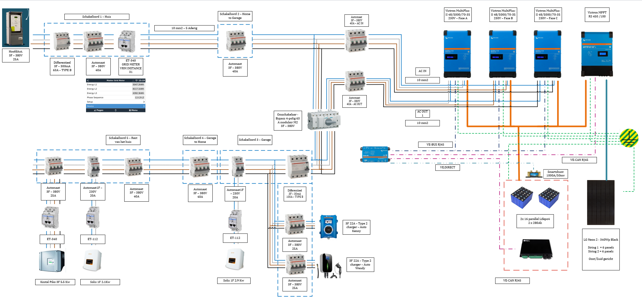
My current setup :

1. House AC IN has 3F+N (25A) + ET340 meter

2. 3 times Victron MultiPlus-II 48/5000/70-35 230V

3. 1x Victon MPPT RS450/100 for battery bank charge

4. 16 * (2x280Ah parallel lifepo4 cells 3.2v) - 48V battery bank with REC-BMS

5. 1x Victron smartshunt 1000A / 50mV

6. 1x Victron EV charger & 1x chinese brand EV charger on AC-OUT1 side

7. 1 x ET112 solar array 2.1KwP on AC-OUT1 Side

8. 1 x ET112 solar array 2.9KwP on AC-OUT1 Side

9. 1 x ET340 solar array 5.5KwP on AC-OUT1 Side

screenshot-2022-12-28-154447.png


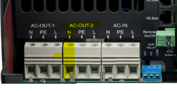
Question 1 : Somewhere in the manual of the Victron states that the neutral in a 3F setup of AC-OUT2 should always be connected. Can anyone explain me why if we do NOT use the AC-OUT2 at all.

1672238942122.png

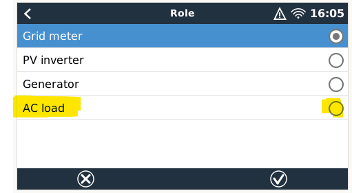
Question 2 : Should I add an additional ET340 with the setting AC LOAD right after the AC-OUT1 to measure the Current/Voltage created by the inverter ? This will lead me to question 3 ...

1672240005839.png


Question 3 : When I look at my dashboad I see wrong numbers (I think) .. What can be wrong :

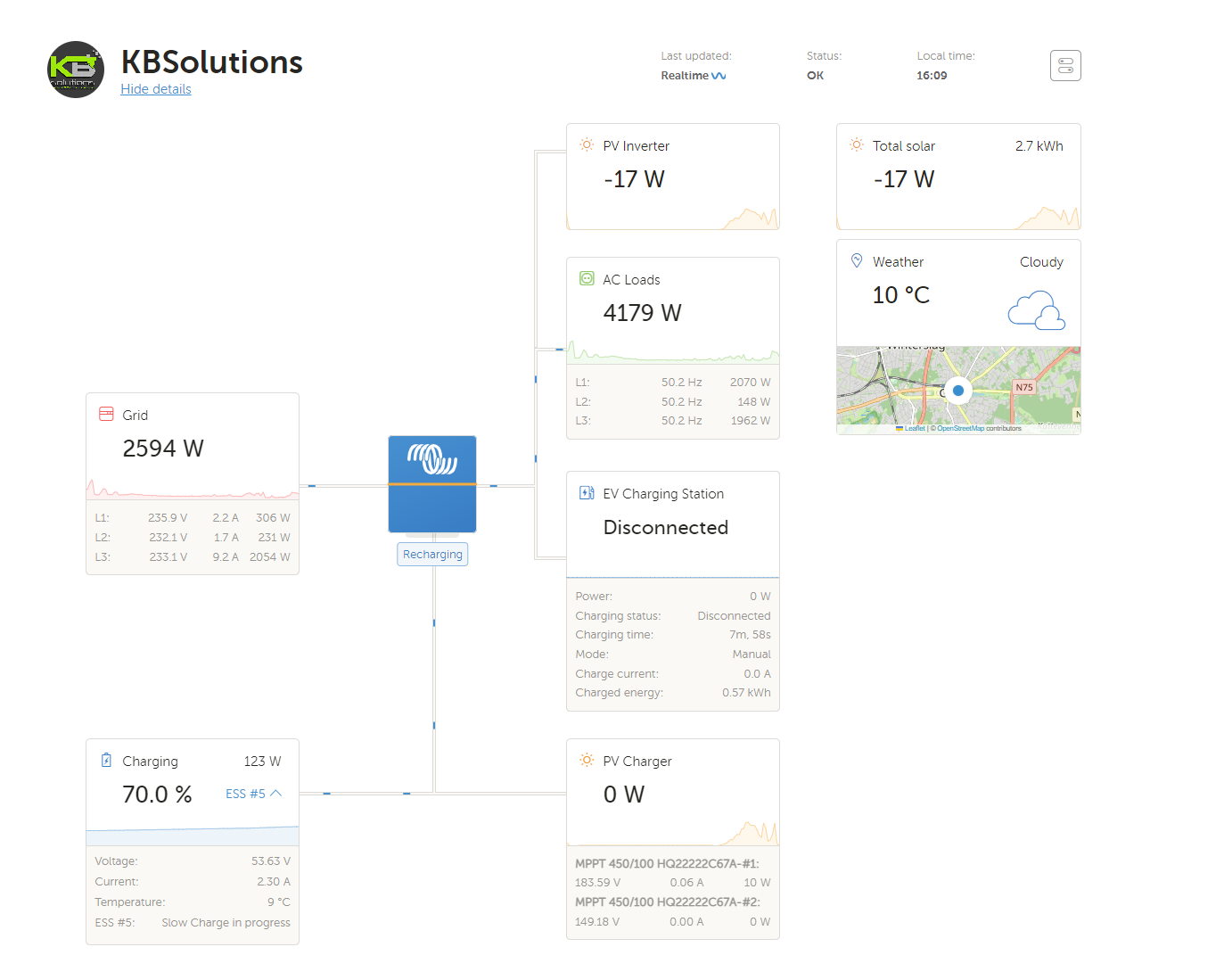
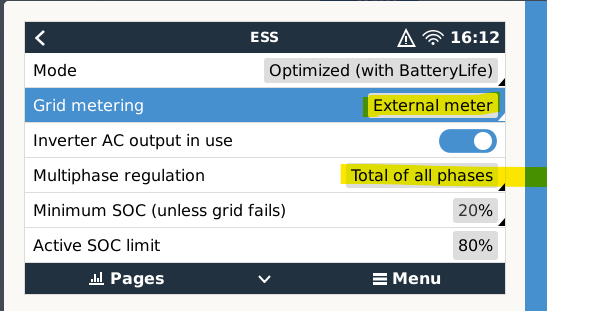
- Case 1 and Set with following settings below : 1672240166837.png

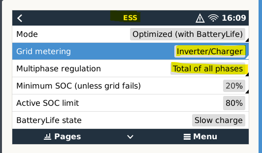
I have this dashboard with following readings ... AC LOADS are not representing Grid load (should be more or less equal as charging battery slowly)

1672240239201.png

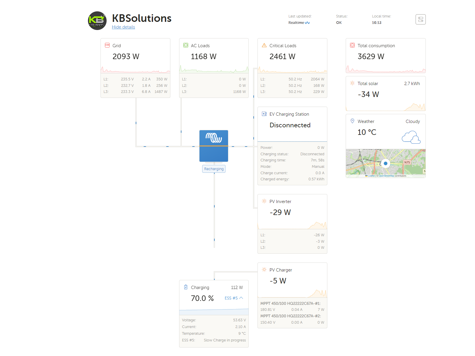
-Case 2 and Set with following settings below :

1672240379161.png


Then I have this dashboard with following readings ... Why do I have critical loads connected ? As none of my AC-OUT2 loads are connected ( only the neutral cable as per question 1)

1672240430319.png

I am getting crazy on question 3 as I don't know what I am doing wrong here ...Or maybe I interpreted it wrong .Would be good if someone could help me out here to understand the issue

Thank you

Kenny

Multiplus-IIcerbo gxmultiple inverters
2 |3000

Up to 8 attachments (including images) can be used with a maximum of 190.8 MiB each and 286.6 MiB total.

2 Answers
daver-1 avatar image
daver-1 answered ·

looking at the pictures i noticed that the naming on the schematic was in Dutch. if you installation is located in Belgium you should now that the latest synergrid approval of the multiplus II is with the current sensors and some electrical inspectors know this. If you use them you can remove the et340 in "schakelbord 1"

I wonder for which reason you put the 40A breaker in "schakelbord 2" as it is of no use.

do you connect the 2.1kw and 2.9kw to the same phase (both are gray)?

is there a reason for the (very expensive) type b 30mA 100A in "schakelbord 4", and just a 63A one in "schakelbord 1"?


Question 1:

Can you please let me know where you did read that the ac-out2 should be connected to the neutral? maybe this Victron manual gives you more info

Question 2:

The multiplus calculates it by itself so no external et340 is needed.

Question 3:

as you connected all loads on ac-out1 they are connected to the critical loads output. in case of a grid failure the multiplus will kick in and supply everything that's connected to that output. Keep in mind that Victron advises the factor 1 rule and make shure that the ac-inverters support ac frequency shifting.

I think you should check every setting or do the full setup again.

2 |3000

Up to 8 attachments (including images) can be used with a maximum of 190.8 MiB each and 286.6 MiB total.

kennybuntinx avatar image
kennybuntinx answered ·

The installation is indeed located in Belgium. And it has been "approved with the ET340"


I wonder for which reason you put the 40A breaker in "schakelbord 2" as it is of no use.

Sure there is a reason - It's more then 50 meters away and I want to cut my electricity supply from the remote location instead of going indoors to the electricity meter :-)

do you connect the 2.1kw and 2.9kw to the same phase (both are gray)?

No that is a mistake on my drawing .. They are on another fase .

is there a reason for the (very expensive) type b 30mA 100A in "schakelbord 4", and just a 63A one in "schakelbord 1"?

Yes/no - The 100A 30mA was cheaper then the 300mA 63A RCCB. In the end the 100Amp was same price as a 63A :-) . And I wanted to have some reserve in current.


Question 1:

Can you please let me know where you did read that the ac-out2 should be connected to the neutral? maybe this Victron manual gives you more info

I can't find it back and maybe it is removed. Doesn't make sense either as we see internally the neutral is connected from AC-OUT1 and AC-OUT2 on the motherboard.

Question 2:

The multiplus calculates it by itself so no external et340 is needed.

Yeah that is what I thought , but why is victron giving the option now ... I am sure 6 months ago it wasn't there yet .

Question 3:

as you connected all loads on ac-out1 they are connected to the critical loads output. in case of a grid failure the multiplus will kick in and supply everything that's connected to that output. Keep in mind that Victron advises the factor 1 rule and make shure that the ac-inverters support ac frequency shifting.

I agree - but the question is more on why I get different readings when selecting "external meter" . There should not be any AC Loads at all visible . Only critical loads. I am sure I cabled everything as it should .


2 |3000

Up to 8 attachments (including images) can be used with a maximum of 190.8 MiB each and 286.6 MiB total.