question

hovyd avatar image
hovyd asked

Pylontech not on Device List of Cerbo GX

I have a Multiplus II 48/5000/70 connected to a Pylontech US3000C battery (one unit) via a Cerbo GX box. No solar, only AC-in for battery recherge. So the main function is basically a glorified UPS for now. The mismatch in sizing is for future use: I only need to power a few computer stations now from this 3kW battery for a 2-hour load shedding bridge and for voltage stability, hence only 1x battery at this stage.


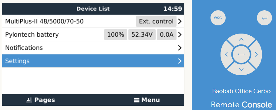
Problem: I cannot get the Pylontech battery to reflect on my Device List, viz
1670307121449.png


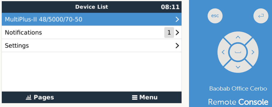
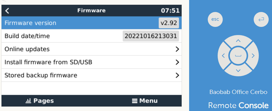
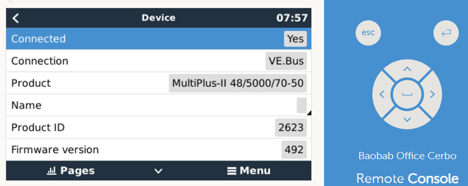
My firmware versions are:

1670307172401.png

1670307194725.png

I followed the Victron&Pylontech (/live/start) manual to the letter (I believe).

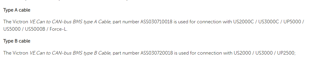
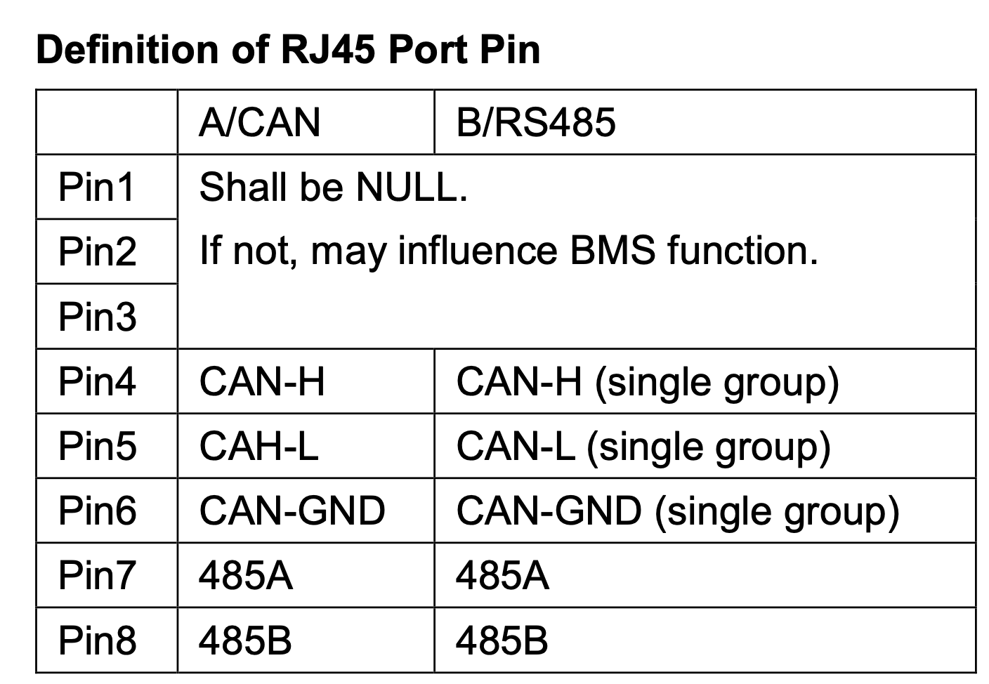
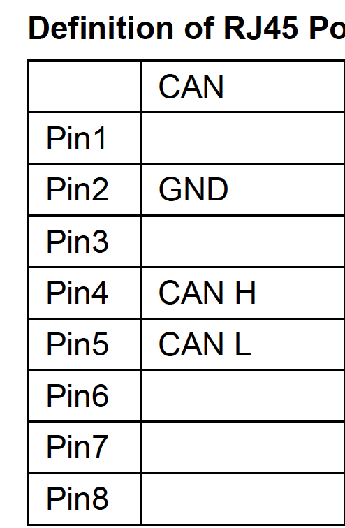
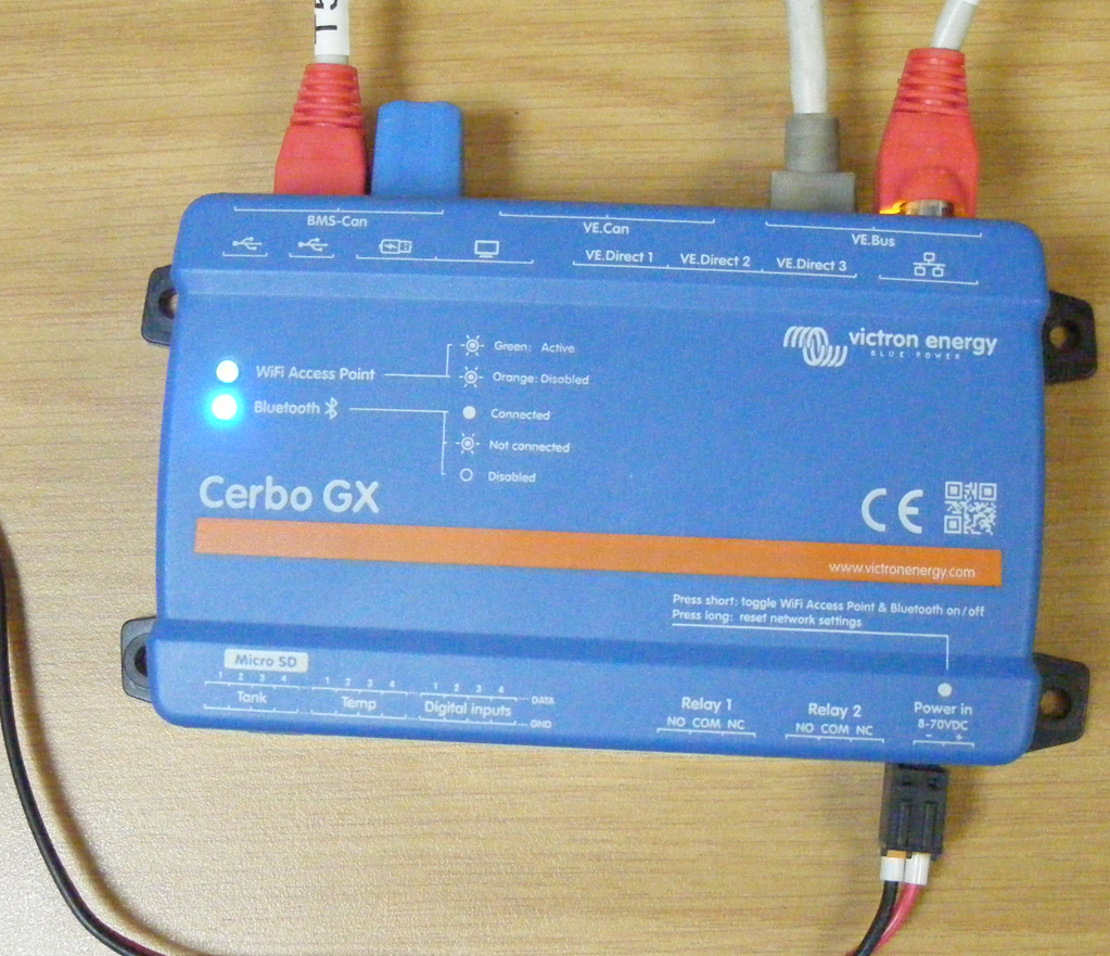
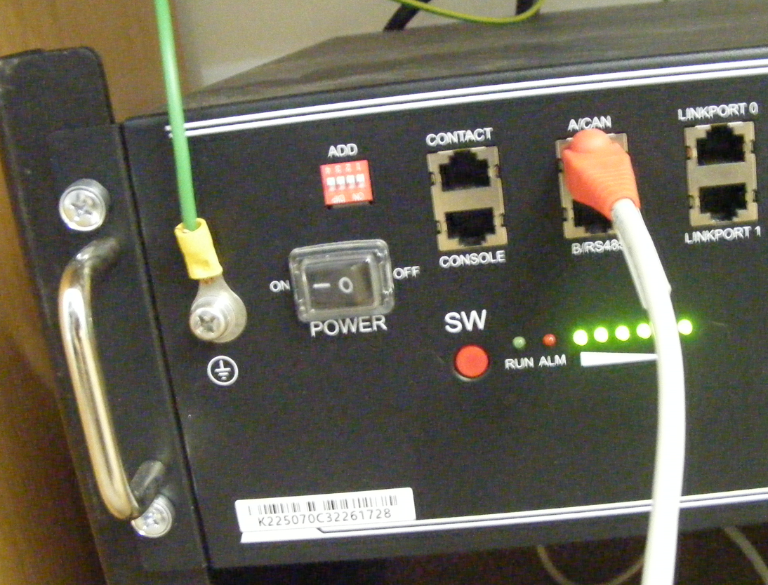
My at GX box connection to battery is a T568A cable from the BMS-Con with the 2nd port plugged with dead-end terminal (supplied with the GX):

1670307632707.png

Power to Cerbo GX is from Multiplus battery terminals:

1670307659436.png

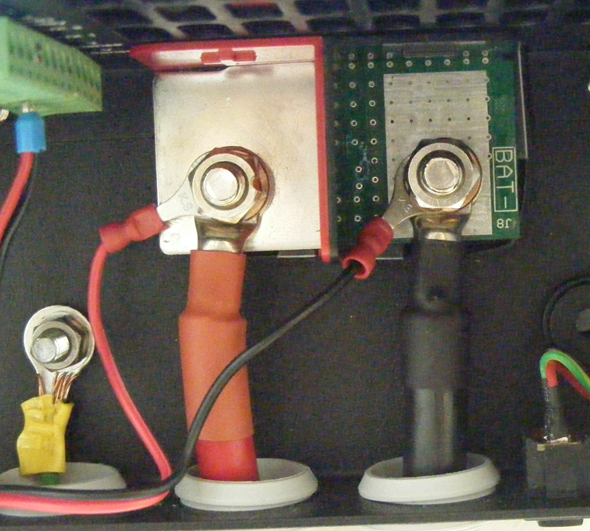
T-sense wire connection can also be seen in the top-left corner.

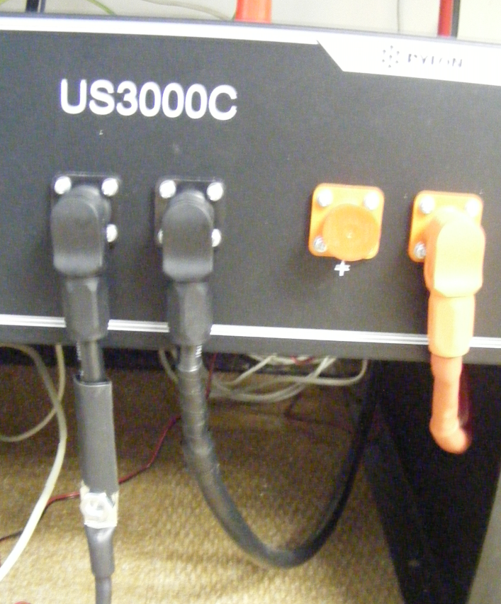
Battery connections:

1670307736885.png


1670307767039.png

Left neg pole used for the temp sense. Removal of this to test if this was the problem did not resolve my issue.


DVCC settings:

1670308115937.png

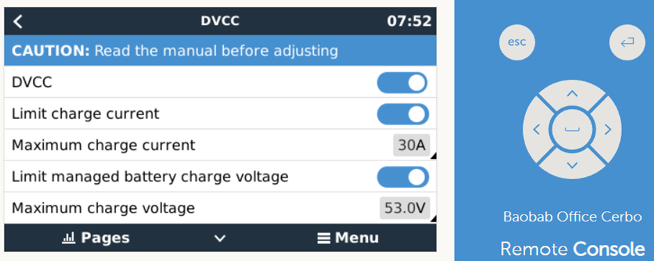
I tried with "Limited Managed Charge Voltage" On and Off.

1670308132704.png

1670308148812.png

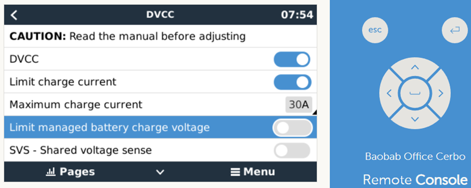
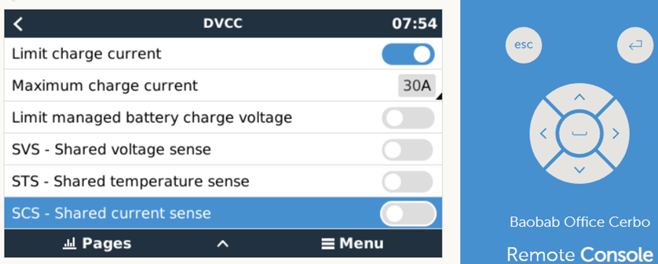
The Victron/Pylontech manual suggested that SVS and STS should be Off, and there should not be a "Limited Battery Charge Voltage"


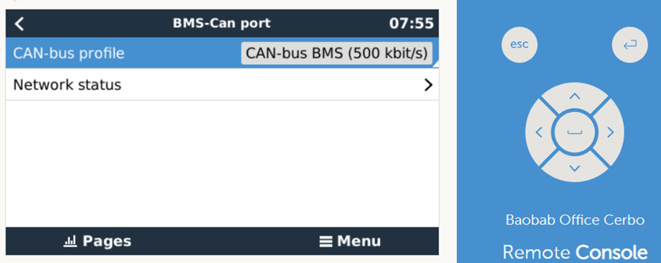
The BMS-Can port speed of 500 kbps is correct, viz:

1670308163729.png

I do a "Redetect System" to try to load the Pylontech.

I really am stuck now as I understand that I need to see the Pylontech listed as a device to proceed further.

Please help!!

Thank you.

Multiplus-IIPylontechgx device
1670307121449.png (39.0 KiB)
1670307172401.png (88.3 KiB)
1670307194725.png (84.7 KiB)
1670307632707.png (1.7 MiB)
1670307659436.png (1.3 MiB)
1670307736885.png (1.7 MiB)
1670307767039.png (1.1 MiB)
1670308115937.png (104.5 KiB)
1670308132704.png (103.6 KiB)
1670308148812.png (104.5 KiB)
1670308163729.png (71.1 KiB)
2 |3000

Up to 8 attachments (including images) can be used with a maximum of 190.8 MiB each and 286.6 MiB total.

3 Answers
niborb avatar image
niborb answered ·

Have you tried an official ASS030710018 cable for the BMS-CAN link? Are you running an up-to-date firmware on everything?

1 comment
2 |3000

Up to 8 attachments (including images) can be used with a maximum of 190.8 MiB each and 286.6 MiB total.

hovyd avatar image hovyd commented ·
1. Not an official ASS030710018 cable; but a tested Type A cable. Does this matter?
0 Likes 0 ·
hovyd avatar image
hovyd answered ·

Solution:

The Type A cable as specified on Victron&Pylontech must not be a straight through connection!!!

It must be a Type A at the Pylontech and a Type B at the Cerbo GX. So it needs to be a cross-over connection.

Issue was resolved:

1670331608868.png

If only Victron specified it as such - I have wasted many hours in fault finding. Sigh.


1670331608868.png (49.2 KiB)
3 comments
2 |3000

Up to 8 attachments (including images) can be used with a maximum of 190.8 MiB each and 286.6 MiB total.

kevgermany avatar image kevgermany ♦♦ commented ·
It's in the Victron manual, close to the start of section 3, CAN-bus wiring.
1 Like 1 ·
hovyd avatar image hovyd kevgermany ♦♦ commented ·

Sorry, cannot find that.

In the Victron&Pylontech manual it only states "The Victron VE.Con to CAN-bus BMS type A Cable, part number....." No mention of cross over to Type B at the Cerbo GX side. The manual has no unique identifier (a very basic problem), so here are the snip views:

1670393309551.png

1670393355799.png

0 Likes 0 ·
1670393309551.png (27.4 KiB)
1670393355799.png (24.4 KiB)
nickdb avatar image nickdb ♦♦ hovyd commented ·

There is no such thing as a "crossover to type B".

Did you make your own cable? The docs are clear not to use the pylon supplied one as well.

The two cable types exist to accommodate the two pin-out variants on the different pylon modules - which are documented in Pylon's guide.

They are also uni-directional so the correct ends must be in the correct port.

Making sure on C models to not connect the first 3 pins.

C models:screenshot-2022-12-07-at-085555.png

others:

screenshot-2022-12-07-at-085630.png

0 Likes 0 ·
Alexandra avatar image
Alexandra answered ·

@hovyd

A simple case of not reading any of the manuals definitely here. It is specified in the Pylontecs own manual and on the victron website in a number of places.

When there are no comms the cable is always the first suspect.

The cable recipie is spelled out in a number of places.

The difference is really the ground pin.

1 comment
2 |3000

Up to 8 attachments (including images) can be used with a maximum of 190.8 MiB each and 286.6 MiB total.

hovyd avatar image hovyd commented ·

Ah, thank you for more clarity.

1. I did research manuals. How I need to know that I have not reached all the manuals is beyond me. So, this critical requirement is not stated in the manual which I would have expected to be sufficient (the Victron&Pylontech manual),

2. For others out there that are not so proficient in the Victron environment; below is the table referred to in the link that Alexandra gave in the reply:

1670487673504.png


(Further to that my conclusion that that a cross-over cable from Type A to Type B is probably therefore incorrect - the cable that worked was made up for me by a Victron knowledgeable technician). The pin-out positions are to be followed.

3. And so I can thankfully learn from this Victron Community.

0 Likes 0 ·
1670487673504.png (21.6 KiB)