question

duswami avatar image
duswami asked

Wiring for ESS

I've read through all the ESS documentation and wiring diagrams and read everything in the forum and watched several training videos about ESS and wiring for ESS and still have some questions, hopefully you all can help me get things sorted out!

When running ESS with no grid feed option and prioritizing PV to run essential loads (AC OUT 1) is a current transformer needed and what is the best method for isolating the essential loads?

Currently, all the loads are in one service panel before the inverter. I have divided the panel so my critical loads are on one side and non-critical loads are on the other side. I have a breaker interlock on the breaker receiving the AC OUT from the inverter and manually throw it when I need to power the side of the panel with critical loads, which is 120V as I am using a 120V Multi. Essentially, its more-or-less a combination of a UPS system and backup system intended for rare grid failure, but I want to use ESS to export as much PV as possible to reduce the Grid AC loads during the day (and charge the batteries.) Generally the system will use Grid AC at night and only use battery consumption when no Grid AC is available limited to a 50% SOC. My current configuration/setup is obviously not an optimal situation as I am not setup to back-feed the grid and have no intention to do so, but currently this 'manual' procedure is what I am doing until I better understand ESS and wiring for it.

When designing for ESS, is it appropriate to move all the critical loads out of the main service panel into its own subpanel and leave the non-critical loads in the main panel and/or should I be utilizing a current transformer? Also, is there a reason to use AC OUT 2 at this point, if the non-critical loads remain in the main service panel, as they don't 'need' to be utilized when Grid AC is not present. However, I would like the option to still use non-critical loads. Therefore, are ALL the loads supposed to be after the inverter on AC 1 and AC 2?

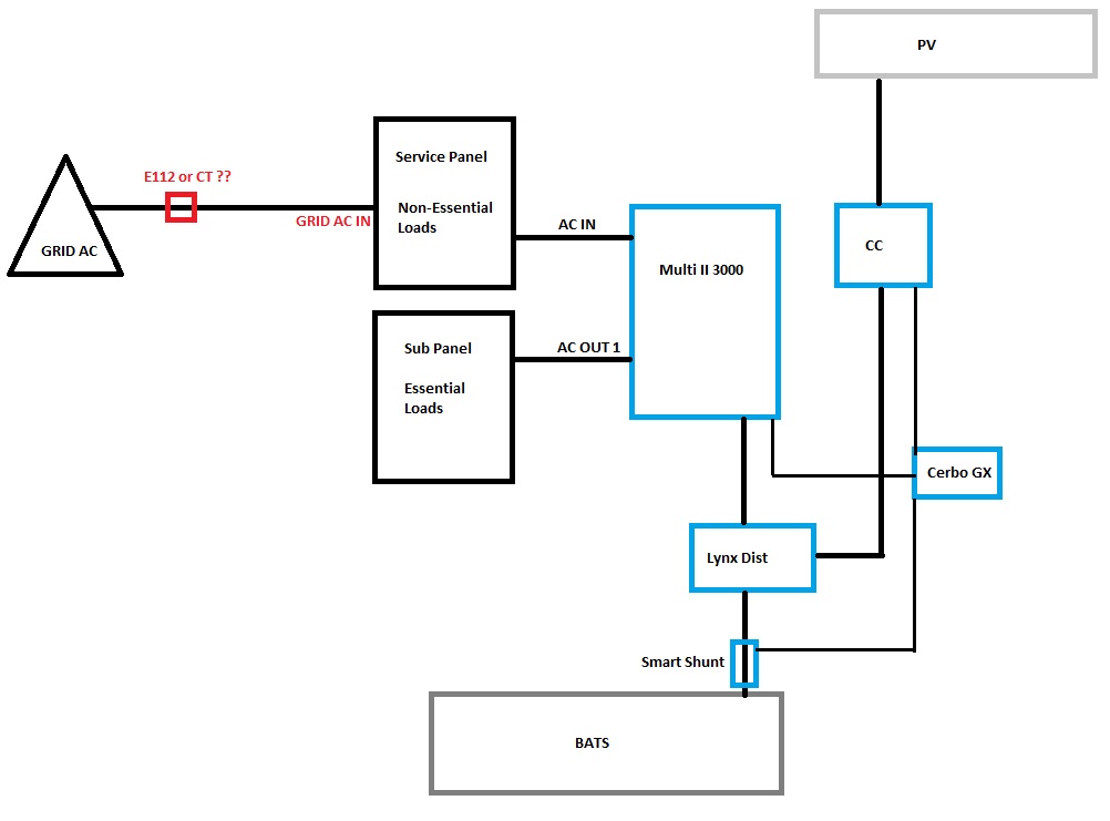
Is it best to have two dedicated breaker panels, one for critical loads (AC1) and one for non critical loads (AC2) and just use the main service panel as a distribution point for the Grid AC and the placement of the current transformer. Trying to understand the best configuration taking into account the ESS and Multi's capabilities. Below are several threads I've posted relating to this subject. Thanks in advance for an insights or suggestions and thank you to those who have already commented in previous posts, I look forward to your suggestions.
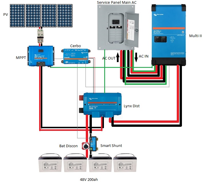
Schematic below

34688-schematic.jpg


How do I setup ESS setup for PV priority

Automatic transfer switch

How does Multiplus II w/Cerbo ESS prevent AC backfeeding?


Multiplus-IIESSwiringct
34688-schematic.jpg (101.4 KiB)
2 |3000

Up to 8 attachments (including images) can be used with a maximum of 190.8 MiB each and 286.6 MiB total.

5 Answers
lifeingalicia avatar image
lifeingalicia answered ·

Hi

yup was a missreading of cockies o something here is the answer I tried posting

more or less simply


if the total load can be delivered by the multi, just connect grid to AC in and critical to out 1 and "other" to out 2 No further CT etc needed - Simple ESS

Grid fails Multi isolates AC IN and only powers Out 1 Out 2 is dead no further back feed etc...

If likely the loads are bigger grid parallel ESS comes in.

Grid connected to "other" loads and to AC In of Multi the critical loads are connected to Out 1.

Here an external CT is needed as the Multi or GX no longer knows the total load. So cant for example see actual feed in as firstly the non critical loads are powered by excess energy (first bats are loaded).

CT can be extended using good quality headphone extension - I use a 3 meter one no problem.

Now grid fails - Multi isolates AC IN and powers Out 1 - the "other are just dead.

In case of grid fail things like SOC max inverter power etc are ignored - Inverter ramps up to max if required and SOC is drawn to near zero if not topped up.

victron-coment.jpgDC coupling if set corectly will charge bats then power other loads and if allowed back feed to grid if grid is available - again depending on settings.


victron-coment.jpg (15.2 KiB)
1 comment
2 |3000

Up to 8 attachments (including images) can be used with a maximum of 190.8 MiB each and 286.6 MiB total.

duswami avatar image duswami commented ·

@Lifeingalicia thanks for the reply. From your revised drawing I see you are splitting the Grid AC between the main service panel and the Multi AC IN. Currently my Main service panel is fed split phase 220/230 with 2 120v legs. The Grid AC Breaker/disconnect is in the main service panel. I'm a bit confused... Is your drawing depicting splitting each leg (120v) between the main service panel and the Inverter? Instead, Can I run a 120V feeder on a 50A single pole circuit from the main service panel to the AC IN on the inverter instead? Or will this complicate the CT's function upstream? I appreciate your suggestions!

0 Likes 0 ·
lifeingalicia avatar image
lifeingalicia answered ·

Can be confusing.

Basically splitting loads into critical and non critical is best so the multi does not need to be seized to cater for all loads.

This then becomes a grid parallel ESS.

Grid comes in goes to non critical part of breaker box.

To get to the critical part of the breaker box it is "looped" through the multi AC IN and AC out 1

With AC coupled PV

PV sitting on the critical path has to be within 1.0 rule. Inverterpower max less or equal Multi power.

This allows this part of PV to be used when a grid loss is present.

If the PV is bigger it should either be splitt or sit on the non critical part of the box (equivalent to AC IN)

DC coupled PV (your case)

Lynx prevent overcharging manages charging - rule 1.0 not relevant.

Settings on GX

DC feed to grid allow can be limited - still bats charged first

Charge current can be limited to load bats more slowly

Grid set point regulates interaction with grid.

If you havent installed / bough yet and have grid - AC coupling is easier

Multi plus GX

Inverter (1 or more before and after Multi) e.g. 3Kw before 3 Kw after

Bats with BMS

VE cabling

Done

It is debateble if AC or DC coupling has higher efficiency but as the sun id free who cares......


1 comment
2 |3000

Up to 8 attachments (including images) can be used with a maximum of 190.8 MiB each and 286.6 MiB total.

duswami avatar image duswami commented ·

Thank you @Lifeingalicia this is very helpful. Finally understanding...


A few things, I already own my equipment, so trying to make this work as DC coupled with Multiplus II. PV inverter not an option at this stage. As I understand it, you cannot keep all the loads in front of the inverter and use a CT to sense Grid AC and permit AC 1 Out to energize the panel when the CT senses no Grid AC as this would still unintentionally back-feed the Multi's AC OUT to the Grid, and I need to isolate the essential loads in a sub panel and can leave the non-essential loads in the main panel. Otherwise, I'd have to also isolate the non-essential loads in a second sub panel on AC OUT 2, correct? In either case, do I still utilize an E112 or CT? I provided a simplified diagram to ensure I understand correctly. Thanks!

ess-wiring.jpg

0 Likes 0 ·
ess-wiring.jpg (59.1 KiB)
duswami avatar image
duswami answered ·

@pau1phi11ips Paul you posted a good answer earlier but something broke on the victron community page and your post disappeared, but I want to respond to the parts I remember as it was helpful.

So basically, as we covered AC coupled PV inverter would be easier along with using a Multi GX. I'm stuck with what I got, so it's DC coupled and a multi ii/mppt/cerbo/ deal. You mentioned I'd need a CT. I believe I need to use the EM24 AV6, correct me if I'm wrong since the Multi can't see what's happening load-wise at the Grid AC, correct?

If you could kindly re-respond and essentially describe you ESS settings and layout as before I'd appreciate it. I think we agreed I would have to isolate the essential loads in a separate panel which would be my AC out 1 and leave non-essentials in the main breaker panel.

2 |3000

Up to 8 attachments (including images) can be used with a maximum of 190.8 MiB each and 286.6 MiB total.

lifeingalicia avatar image
lifeingalicia answered ·

Sorry forgot US split systems

Technically yes you can just run a 120V L1 to neutral or L2 to neutral via a breaker to the Ac in of the 120V multi and put your criticals behind this again with fusess / breakers as per code.

The multi and inbuild ct will give you what is going on on that line and show back feed.

If you need to know all consumption e.g. L1 & L2 you need an electronic meter eg.g. gavani etc.

Which multi do you actually want to use? You might want to double chek with a Victron dealer.

1 comment
2 |3000

Up to 8 attachments (including images) can be used with a maximum of 190.8 MiB each and 286.6 MiB total.

duswami avatar image duswami commented ·
@Lifeingalicia Thanks for the clarity. I have a Multi II 48v 3000/35 120V, and I have an EM24 AV6 coming in a few days. I think that should do it? EM24 is technically for 3 phase systems but I believe it will work on split phase as well. The CT comes with 2 meter clamps. Do I use both, one on L1 and one on L2?


0 Likes 0 ·
lifeingalicia avatar image
lifeingalicia answered ·

Hi

sorry I dont know the EM24 well except it is OK for split phase systems so I would asume you connect directly or above rated power use the CT on L1 & L2 but check the manuals.


2 |3000

Up to 8 attachments (including images) can be used with a maximum of 190.8 MiB each and 286.6 MiB total.