question

duswami avatar image
duswami asked

How do I setup ESS setup for PV priority

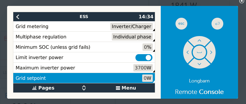
Confused about ESS setup. Here's what I'm trying g to do...

When inverting, I want the CC to charge the bats (if needed) and provide the surplus to the inverter to power the AC loads (AC out). Since there is no AC Main present, if the AC load exceeds the PV output I assume the PV will be combined with load from the bats. Confused about the proper settings.
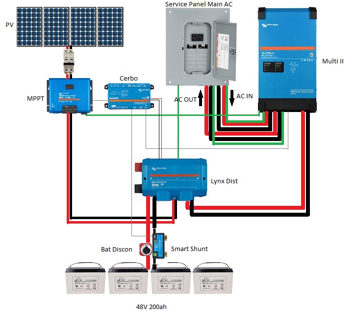
My system is: (48V)

Multiplus II 3000/35 120v

SSCC MPPT 150/45

1.4kw solar

Smart Shunt

Lynx Dist

200AH LA AGM (48V)


Multiplus-IIESSMPPT SmartSolar
2 |3000

Up to 8 attachments (including images) can be used with a maximum of 190.8 MiB each and 286.6 MiB total.

3 Answers
Jason - UK avatar image
Jason - UK answered ·

@Duswami ESS needs a AC supply on the AC in connection to work correctly. With no incoming mains connection, as far as I am aware, you can not use ESS. Do you have a basic schematic of your system? Is the PV direct to the batteries (DC to DC) or is it on the AC side, using the Multiplus the charge the batteries?

1 comment
2 |3000

Up to 8 attachments (including images) can be used with a maximum of 190.8 MiB each and 286.6 MiB total.

duswami avatar image duswami commented ·
Thanks for responding, my wiring diagram is unavailable from my current location at the moment but it's fairly straight forward...


Multi II

MPPT CC

Lynx dist

Smart Shunt

Cerbo GX

48V Bat system/ 1.4kw solar

AC mains present

My PV is tied to the bats via the Lynx Dist. Currently, I'm getting AC Mains and distributing AC directly back to the main panel using breaker interlocks (keeping AC out on the inverter isolated until there is a grid failure) at which point I disconnect the AC Mains to prevent backfeeding to the grid as I am not net metering and don't intend to sell power back. I essentially want all the benefits of ESS without backfeeding the grid, but can I do that without a meter as I'm confused as to how I'd keep AC from leaking onto the grid as well. As I understand it, it seems like I'd choose 'keep bats charged' and keep the SOC at 95% to begin with... I get a bit lost after that. Also, if I'm using ESS, and I pull more Amps than my PV supply can provide, it appears power assist would not function, which is a feature I need at times since the PV system is rather small being 1.4kw.

0 Likes 0 ·
sharpener avatar image
sharpener answered ·

Sounds like you need to set Grid setpoint=0 to begin with.

1654868206320.png

A schematic would help, but for sure if you have loads on AC In then you will need a CT, if you put them on AC Out you may not. However ESS will prioritise loads over charging the batteries so maybe will not do exactly what you want.


1654868206320.png (55.0 KiB)
1 comment
2 |3000

Up to 8 attachments (including images) can be used with a maximum of 190.8 MiB each and 286.6 MiB total.

duswami avatar image duswami commented ·

I've attached a basic wiring diagram excuse the Microsoft paint, as far as the CT, Are you referring to a current sensor transfer switch? OK I understand with the grid selection. schematic.jpg

0 Likes 0 ·
schematic.jpg (101.4 KiB)
sharpener avatar image
sharpener answered ·

CT = current transformer (generic name) = current sensor (Victron name), sorry for any confusion.

It's not clear from your diagram what the arrangement of the connections between the Multi, the AC distribution and the grid connection are. Also in yr other postings you talk about changeover switches/contactors/relays, can we see a schematic for what you propose to do here? It sounds over-complicated, you may be able to do it with the built-in functionality of the Multi.

A common ESS setup in Europe would be grid to AC In, maintained loads on AC Out1 (ESS will automatically keep these going during grid failure), non-maintained loads on AC Out2, in this configuration ESS uses the Multi's internal current sensor to achieve zero grid feed-in. I have this setup and it works fine. But I see you are on 120V so it may need to be different where you are.

If you have more AC load than the Multi's internal 50A transfer switch can carry then you will have to put some non-maintained loads on the AC In side and then you will need a external current sensor as shown on the data sheet here.

1 comment
2 |3000

Up to 8 attachments (including images) can be used with a maximum of 190.8 MiB each and 286.6 MiB total.

duswami avatar image duswami commented ·

Thanks for replying.

Not sure how to better portray the connections from the Multi to and from the AC visually, maybe I can do better explaining it.

I have the Multi wired directly to the service panel (Grid) with a 50 A breaker in the panel (AC IN) . I have the Multi AC OUT 1 wired back to the service panel with a 50 A breaker. Note, since the Multi version (MultiPlus-II 48V 3kVA 120V ) I have is 120v, I am only energizing one side of the panel which I have prioritized my critical loads on. The DC from the battery comes into the Multi in the usual manner, via the Lynx Distributor.

Currently, I have breaker interlocks on the Multi AC OUT 1 service panel breaker and only manually close that breaker when there is no Grid AC Power as I do not want to backfeed the grid. I do not have loads on the AC OUT 2 . I am unclear as to whether using AC OUT 2 is needed? When I have no Grid AC present, I'm running in Inverter mode, wishing to prioritize PV consumption, then battery consumption. I'm new to ESS, so trying to stumble through it.

I've set current limitations in the Multi not to exceed the AMP rating, and don't intend to exceed 50A.

I will add, there are loads before the Inverter. In essence, the service panel provides all loads to the house. Only when the MP is inverting AC OUT is providing to half those loads on one side of the breaker box.

Hope this helps, I appreciate your insight.


0 Likes 0 ·