question

ge-org avatar image
ge-org asked

How to control LFP DoD in a Lean Backup Power System w/o SoC loop?

backup-power.jpegLean Backup Power System for Ukraine Homes (draft)

Dear All
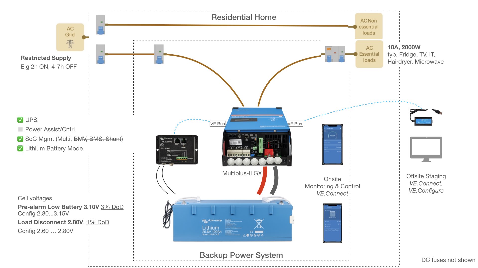
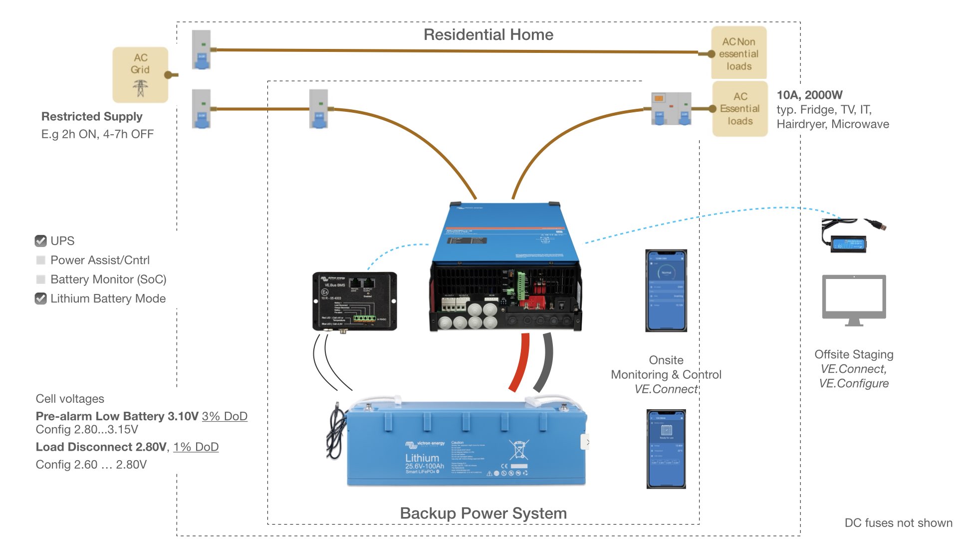
I‘m designing a Victron Energy backup (my first one) for homes in Ukraine. System shall be simple and robust, for largely unattended operation. Must expect heavy duty cycles: Fast charging the battery when grid available (2h), deep cycle battery power usage meanwhile (7h). Need system self-protection: Finding active outlets, some users may just draw power down to the limits, unaware of appliance power ratings, and no time to bother about status panels. Folks are forced to pick other priorities these days.

So what can be done in a lean system in absence of a decent SoC control loop (see drawing) to protect expensive LFP battery against frequent 1% DoD‘s and pre-mature aging ?

A- Can MultiPlus-II be setup somehow to shutdown inverter already on Low Battery Pre-alarm from LFP/BMS (cell voltages = close coupling) ? When set to 3.15V it might keep LFP at least above a 3-5% DoD floor.

A1- Setup via VE.Connect/Configure (couldn‘t find means) ? Eventually thru a (new) Assistant ?

A2- Wire BMS Pre-alarm signal to a programmable Multiplus-II terminal (K1, AUX), and assign some logic/assistant ? But would have to coexist with VE.Bus controls …


B- Wire BMS Pre-alarm signal to a AC-OUT relay to disconnect the AC Essential Loads ? But then how to avoid toggling ?

C- Play with MultiPlus-II DC Input Low settings (battery voltages = loose coupling) ?

D- Other means ….

Thanks in advance for any contribution

BMSSOCupslifepodocumentation
backup-power.jpeg (177.5 KiB)
1 comment
2 |3000

Up to 8 attachments (including images) can be used with a maximum of 190.8 MiB each and 286.6 MiB total.

Alexandra avatar image Alexandra ♦ commented ·
@Ge Org

Is there a reason why you cant just install a bmv on there and then have the SOC problem.solved?

The issue with using voltage is that a battery under load (depends on how much internal resistance it has) will have aome voltage collapse.

But generally a system can be programmed with voltage to switch off (before full dod if you know that voltage) and restart after a voltage recovery.

0 Likes 0 ·
3 Answers
Alexandra avatar image
Alexandra answered ·

Again the battery low cut off on the inverters works quite well. Internal soc (which you can also use to cut off) works well if there is some grid charging.

The smart shunt is cheaper that the bmv and unless you need online monitoring and have network for that the cerbo is actually unnecessary.

Look at the multi RS/GX is has it all in one package and can have a ve direct connected to a global link. Not sure how it compares to the other set up in cost but simplicity is there.

https://www.victronenergy.com/media/pg/Multi_RS_Solar/en/installation.html#UUID-1b279b10-6900-c40f-a9d0-53306880fa1c

2 |3000

Up to 8 attachments (including images) can be used with a maximum of 190.8 MiB each and 286.6 MiB total.

ge-org avatar image
ge-org answered ·

Thanks @Alexandra . So why not just install BMV to tackle SOC ?
Well, for subject use case, humanitarian aid, its mainly for two reasons

  1. Budget … with funds primarily spend on battery capacity
  2. Robustness …. with as few boxes and connectors as possible. Transportable setup in simple housing for use in a flat.

Technically a BMV (712) is the right thing. For my case ideal if BMV could instruct MultiPlus-II to shutdown inverter on Low SOC. Just not found inline control option, i.e. good way to bridge the VE.Direct to VE.Bus gap. Not considering Cerbo GX, and existing VE.Bus BMS seem also no help here.

Without inline control, and down to using BMV‘s SOC Relay to drive an AC-OUT cutoff relais, one would have to assess

  1. Existing BMS pre-alarm drives timerized cutoff relais (15 EUR). 95% DoD protection. 1500 LFP cycles ?
  2. Additional BMV Low-SOC relay drives simple cutoff relais. 80% DoD protection, and configurable. 2500 LFP cycles.


2 |3000

Up to 8 attachments (including images) can be used with a maximum of 190.8 MiB each and 286.6 MiB total.

ge-org avatar image
ge-org answered ·

Long Journey - Happy End

I came a long way, and Documentation Team probably can help others to go straight. Here my detours and helpful tour guide …

Seeking for lean UPS — browsed schematic booklets and quite a few product manuals — got impression Multi has role in SoC, but relies on external boxes — me asking for something simple in this forum — @Alexandra pointed to Multi GX for integration/flexibility — since Multi GX manual for GX aspects seems still a bit WIP, i turned to Cerbo GX manual ….. to ultimately find the SoC system concept 8.2. Battery state of charge (SoC), still in a product level doc, but making SoC fragments from other docs now meaningful for me.

Appologize if i overlooked such concept intro somewhere at system/schematics level of content. And yes, I’m not registered as a professional.

So no complains, just food for thought.

The good thing for me: I turned to Multi-GX, giving me more deployment options, at given budget.

backup-power.jpegLean Backup Power System for Ukrainian Homes (draft II)


backup-power.jpeg (183.2 KiB)
2 |3000

Up to 8 attachments (including images) can be used with a maximum of 190.8 MiB each and 286.6 MiB total.

Related Resources

Victron VE.Bus BMS product page

Victron 3rd party BMS compatibility page

Additional resources still need to be added for this topic