question

Louis van der Walt avatar image
Louis van der Walt asked

Victron VenusOS driver for serial battery BMS - JBD / Daly / JKBMS / Renogy / ECS , etc.

Hi

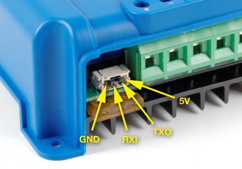
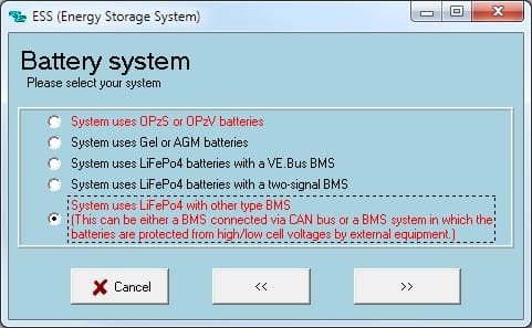
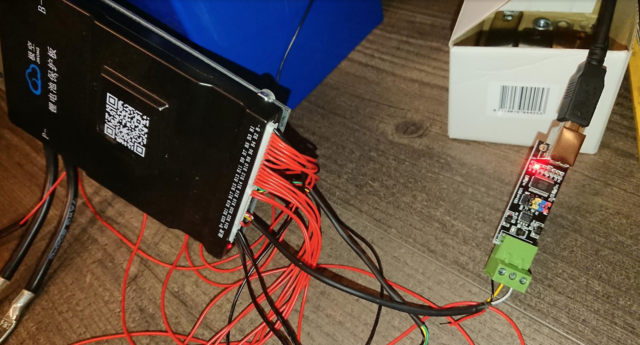
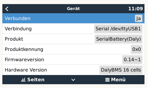
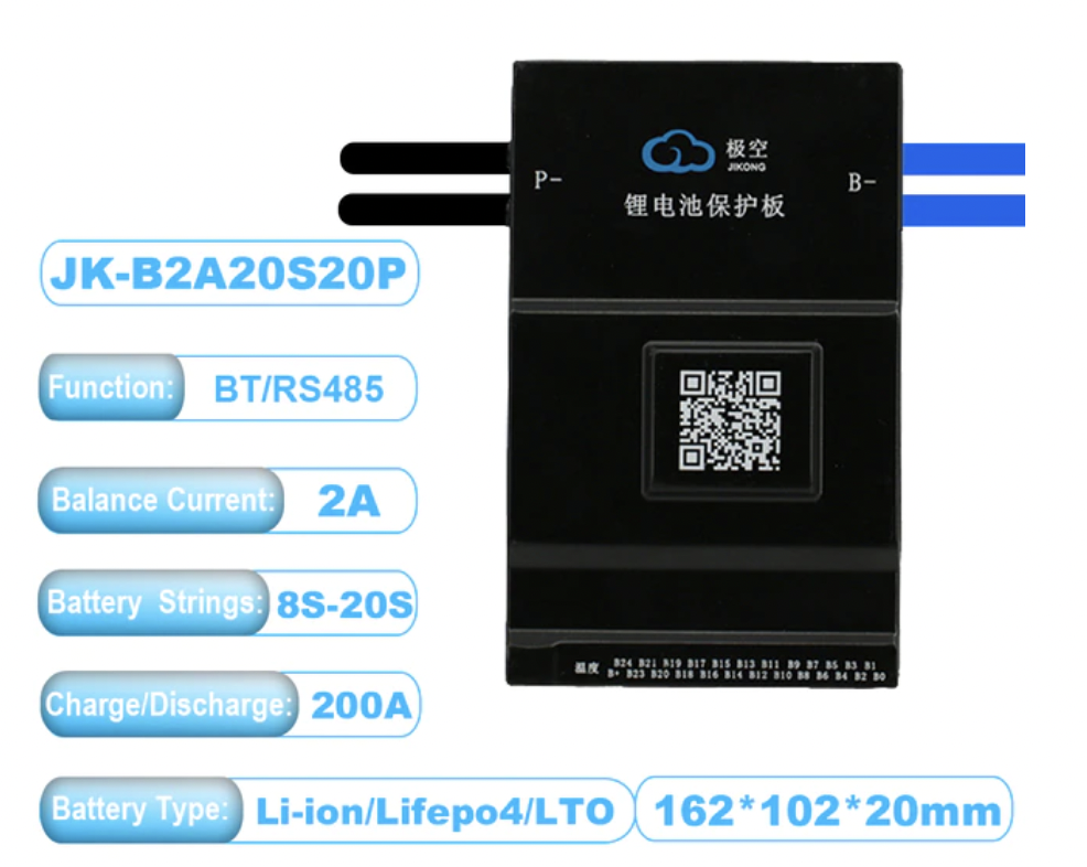
I have created a VenusOS driver that can talk to BMS/Batteries that has serial communications (instead of the normal CANbus). RS485/RS232/TTL/UART and Venus 2.80+ have been tested.

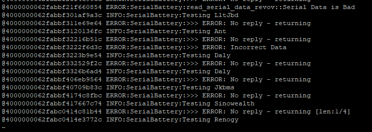
Currently it works with

  • JBD BMS (LLT Power / Overkill Solar)
  • Daly BMS (Daly Smart BMS / Daly Sinowealth based BMS)
  • ANT BMS
  • MNB spi BMS - disabled by default as it requires extra libraries installed to work. Contact @Mike Dorsett for information
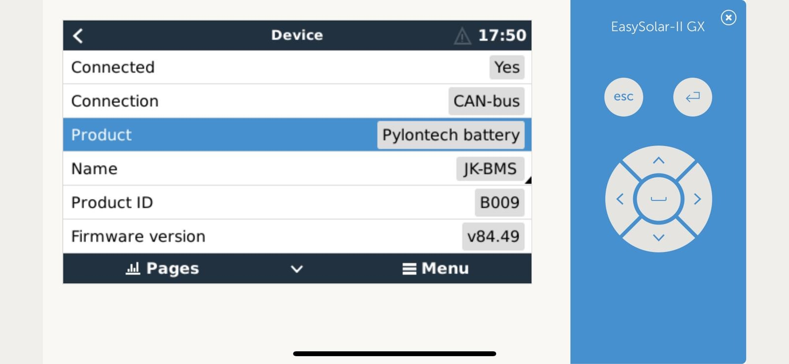
  • JKBMS / Heltec
  • Renogy
  • Tian Power BMS (Revov battery / LifePower)
  • ECS (GreenMeter)


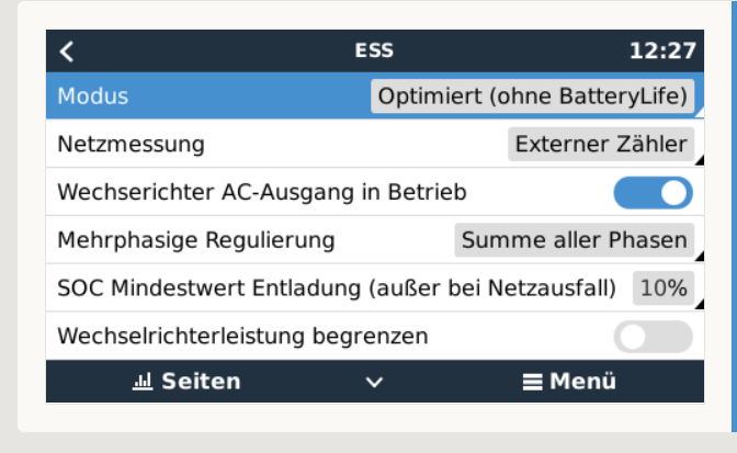
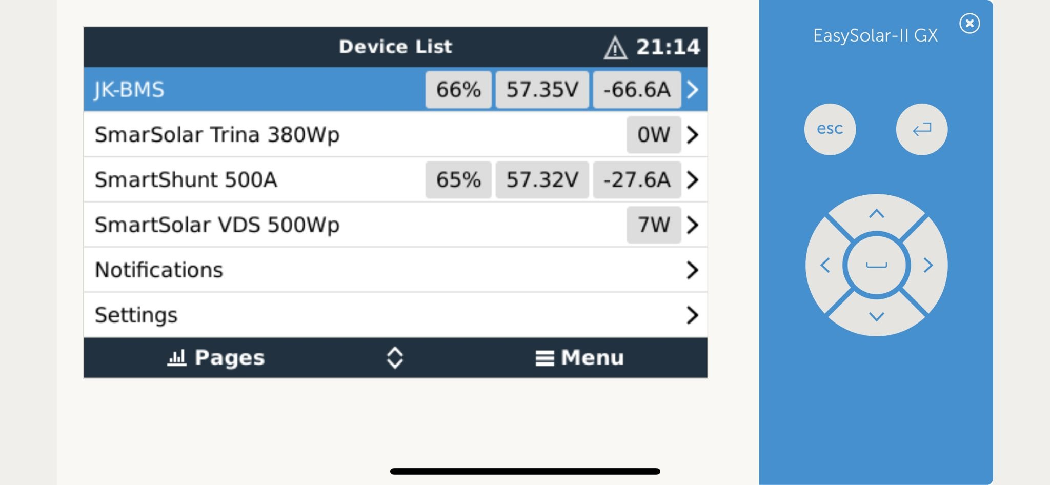
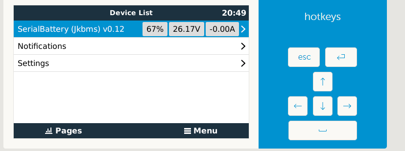
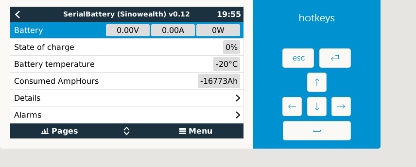
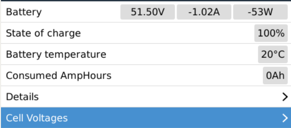
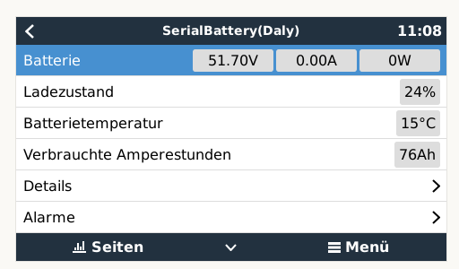
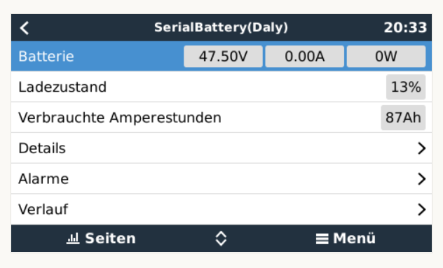
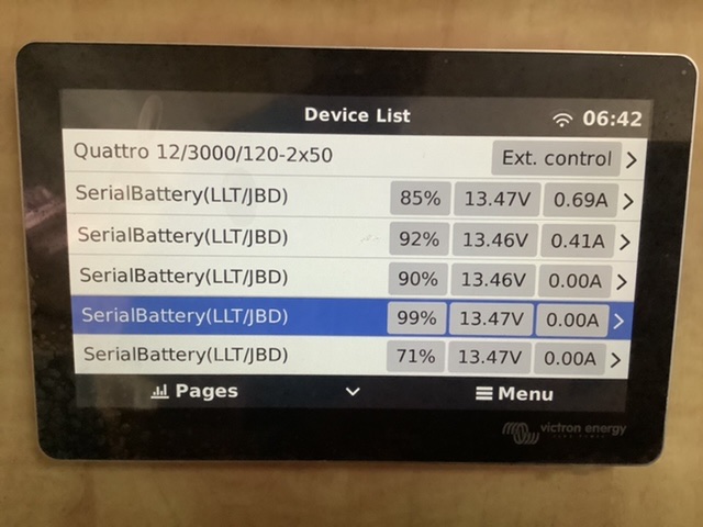
The driver will act as Battery Monitor inside VenusOS which will also publish the battery to your VRM.
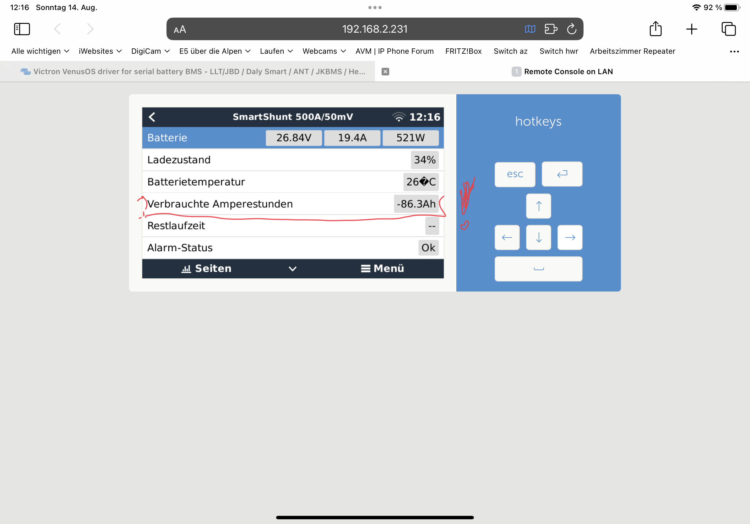
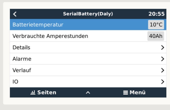
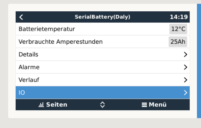
The following values are included:

  • State Of Charge
  • Voltage
  • Current
  • Power
  • Can handle batteries with from 3 - 32 cells
  • battery temperature
  • min/max cell voltages
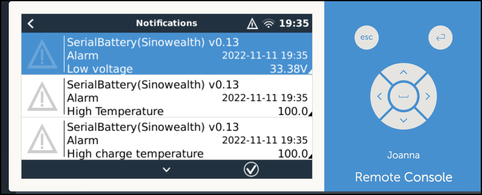
  • raise alarms from the BMS
  • available capacity
  • history of charge cycles

The current release is on GitHub if you want to check it out.
You can up-vote for your BMS to be added to the driver in the here on github.
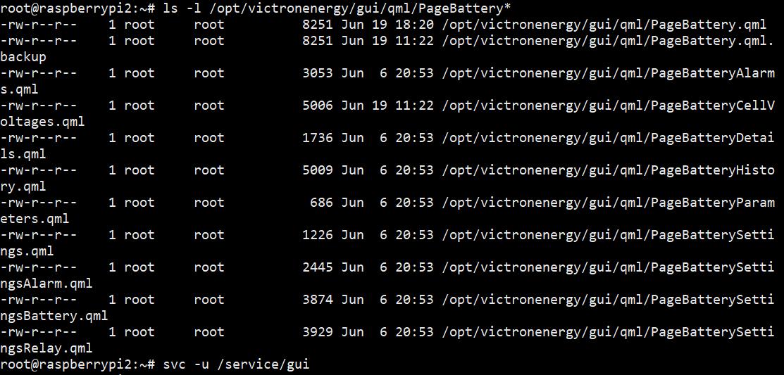
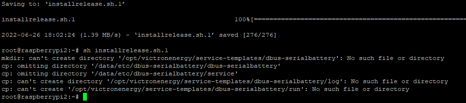
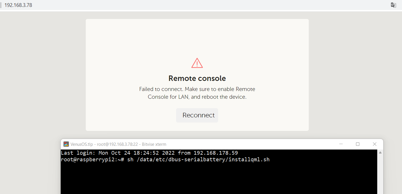
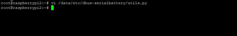
Documentation with install instructions and troubleshoot is available here


BMV Battery MonitorVenus OSBMSrs485
2 |3000

Up to 8 attachments (including images) can be used with a maximum of 190.8 MiB each and 286.6 MiB total.

126 Answers
Pedro Rampolla avatar image
Pedro Rampolla answered ·

I have 2 overkill solar (JBD) BMS and only one is seen on my RPI running 2.85. If I’m reading right, after 2.73, multiple BMS may not be recognized. Is that still the case?

1 comment
2 |3000

Up to 8 attachments (including images) can be used with a maximum of 190.8 MiB each and 286.6 MiB total.

Louis van der Walt avatar image Louis van der Walt commented ·

Yes if you want to see both then downgrade to the 2.73 firmware for now.

This is part of the reason that the multiple battery bank feature is taking so long as we need this sorted first :(

0 Likes 0 ·
elko avatar image
elko answered ·
Good evening, I use this driver with DalyBMS.
I noticed that the values of power and current jump very strongly. e.g. within one second between 400W -> 720W -> 1250W and back again.
Can you do something about that?
4 comments
2 |3000

Up to 8 attachments (including images) can be used with a maximum of 190.8 MiB each and 286.6 MiB total.

Louis van der Walt avatar image Louis van der Walt commented ·
@elko, the driver only publish the power draw that it gets from the BMS.

And in normal systems your inverter will draw what is needed from all the sources to power the currently need which constantly change.
Unless you have a fixed constant load, and no fluctuations in sources (changes in the MPPT from the sun), then the power from/to the battery will be changing all the time.


With that said the Daly's comms protocol is the slowest of all the BMS supported so it is very possible that you might see delayed values from a Daly BMS in you GX system. There is a bit of improvement coming for the Daly in the next release, but we have to work with the hardware that is there.

0 Likes 0 ·
elko avatar image elko Louis van der Walt commented ·

Hello,

Thank you for your answer.


Can you already estimate when you finished this version? :)

Or does a beta exist? I'm happy to test it.


I had to reinstall VenusOS (version 2.9:10). I noticed that after I added my BMS with your driver, my MP2 is set to "external control". Is it correct?

I mean it wasn't like that before.

1653646966587.png

1653647280073.png

1653647311865.png


0 Likes 0 ·
1653646966587.png (25.1 KiB)
1653647280073.png (58.4 KiB)
1653647311865.png (37.7 KiB)
Louis van der Walt avatar image Louis van der Walt elko commented ·
External Control is fine for 2.90 firmware. Victron changed it in there. You can read more details on that in their release notes.


Best would be to subscribe to the multi bank ticket in the github repository. Any changes and betas will be published there.

0 Likes 0 ·
samuel-brucksch avatar image samuel-brucksch commented ·
You need a fmw update for your Daly. I had the same.
0 Likes 0 ·
mjbou avatar image
mjbou answered ·

To: Louis van der Walt

Looks like a very good work! Can i use it without a Victron inverter? Raspberry Pi, 2x Victron 100-50 SCCs and a JK BMS 200A 8S 2A balance. I have a spare Victron USB to VE.Direct cable i can modify. ps. i was using DYKB 200A 10-24S ANT BMS, with inaccurate current sensor; was planning to get a Victron Smart Shunt, but looks like dont need it with the JK and this setup. Thanks. pps. the DYKB 200mA balance got too hot, burned a resistor. Later 3x 10⁴RONS MOSFETs on the charge side got blown, temperature reading fault first. Both charge and discharge current were severely limited.

3 comments
2 |3000

Up to 8 attachments (including images) can be used with a maximum of 190.8 MiB each and 286.6 MiB total.

Louis van der Walt avatar image Louis van der Walt commented ·

The inverter is not a requirement, but the driver on the GX (GX can also be running on the rPi) will not be able to limit the power use if a Victron inverter is not present.

So at the very least you need a GX device running VenusOS with the driver, and a BMS connected to the GX. All the rest just work nicely together but is not requirements.

0 Likes 0 ·
mjbou avatar image mjbou commented ·
anyone know which wire colours are tx & rx on the Victron USB to VE.Direct adaptor? i know it also needs power from both ends, being isolated.
0 Likes 0 ·
Louis van der Walt avatar image Louis van der Walt mjbou commented ·

I don't know the colors but this should help

0 Likes 0 ·
Nicholas Rotenko avatar image
Nicholas Rotenko answered ·

Louis, I can install your driver manually. But I tried it through KWindrem's SetupHelper and couldn't get it to work. I tried:

Package name: dbus-serialbattery

GitHub user: Louisvdw

GitHub branch or tag: latest (also tried v0.10)

Am I doing anything wrong? It would be really handy if this was to work.

1 comment
2 |3000

Up to 8 attachments (including images) can be used with a maximum of 190.8 MiB each and 286.6 MiB total.

Louis van der Walt avatar image Louis van der Walt commented ·
I have not created a setup to work with SetupHelper. There is a ticket open to do that.
0 Likes 0 ·
bertie-bezuidenhout avatar image
bertie-bezuidenhout answered ·

Hi Louis van der Walt, I am probably very late and to be honest, I am not looking forward of reading though all the comments and replies to find what I am looking for. So, let me het straight to the point. I have one of those batteries, a Victron Multiplus Inverter and a Victron CerboGX and wish to import the battery data into the CerboGX. However, I would prefer to use my Raspberry Pi with a 2-Channel RS485 HAT as the interface. So, perhaps you have the answers to help me, else I must spend time incorporating your scrips into what I have. I would therefore appreciate any assistance to mak life a lot easier for me.

5 comments
2 |3000

Up to 8 attachments (including images) can be used with a maximum of 190.8 MiB each and 286.6 MiB total.

Louis van der Walt avatar image Louis van der Walt commented ·

Hi @Bertie Bezuidenhout

If your hat is already set up with your PI on the VenusOS image, just follow this guide. https://github.com/Louisvdw/dbus-serialbattery/wiki/How-to-install

0 Likes 0 ·
bertie-bezuidenhout avatar image bertie-bezuidenhout commented ·

Good day Louis, in my previous posting I said that “I wish to import the battery data into the CerboGX”. I looked at the detail of the link you sent me and noticed that CerboGX users cannot use the Automatic installer. I also noticed that “the Cerbo GX currently has a known issue where this install method is not working. It should be fixed in future VenusOS releases.” So, now the question is: am I missing something because I want to use the Cerbo GX, but I don’t know how to get it onto that unit. If I download and flash the latest release venus-data.tar.gz to the root on a USB drive for the purpose of installing the software unto the Cerbo GX, I am confronted with another issue: which USB port do I have to plug the USB Drive into?

0 Likes 0 ·
Louis van der Walt avatar image Louis van der Walt bertie-bezuidenhout commented ·

Hi @Bertie Bezuidenhout

Just below the Auto Installer you will find the SSH installer script option. Just follow those steps. You will need to create root access (just follow the Victron guide linked in the steps and then run two commands in the SSH terminal.


PS. Not that you will be using it, but for the autoinstaller you can plug the flash drive into any usb port and it will pick it up.

0 Likes 0 ·
bertie-bezuidenhout avatar image bertie-bezuidenhout commented ·

Hi Louis, thanks for your patience with me and explaining what to do. I will try the SSH (Putty) route during the coming days. I am just very cautious. By the way, I posted a question for you on Power Forum hoping that you have perhaps done some work on getting the MicroCare MPPT data into the Victron Cerbo GX.

0 Likes 0 ·
bertie-bezuidenhout avatar image bertie-bezuidenhout commented ·

Hi Louis, it appears as if the revov.py was not installed as part of the “wget https://raw.githubusercontent.com/Louisvdw/dbus-serialbattery/master/etc/dbus-serialbattery/installrelease.sh” installation. Must I create a revov.py file in the /data/etc/dbus-serialbattery/ folder, or what must I do to get the system to work correctly?

0 Likes 0 ·
Louis van der Walt avatar image
Louis van der Walt answered ·

Release v0.12 is available

https://github.com/Louisvdw/dbus-serialbattery/releases/tag/v0.12

The big changes are for fixing issues experienced with the driver on 2.80/2.90 firmware interfering with other devices, Tian/Revov BMS support and fixes for Daly BMS values.

3 comments
2 |3000

Up to 8 attachments (including images) can be used with a maximum of 190.8 MiB each and 286.6 MiB total.

juf avatar image juf commented ·

Hi,

is this normal that with a jk-bms I don’t see the consumed Ah?

655f86d9-5826-4689-b227-f7d5a8d4578c.jpeg
I have run the 0.12b with Venus os 2.90~22.

but this will happens with all version Iˋv test.

My smart shunt will show this.

a035e04c-37b8-476d-abcd-effc4c162c81.jpeg

regards

0 Likes 0 ·
Louis van der Walt avatar image Louis van der Walt juf commented ·

Hi @Juf

Yes that is normal. Not all BMS publish everything that Victron has available in the GX. There are a few BMS that do not publish the remaining capacity (like the JKBMS for instance), but I have created a ticket that we can calculate it for those BMS using the SOC%.

https://github.com/Louisvdw/dbus-serialbattery/issues/181

1 Like 1 ·
juf avatar image juf Louis van der Walt commented ·
Thx for clarification. :-)
0 Likes 0 ·
beliffm avatar image
beliffm answered ·

Hi Louis,
i just installed V 0.12 and it is working flawlessly with two battery banks connected via two JK-BMS systems.

One question though: It says in the release notes that the single cell voltage feature was added, but it seems to me that the corresponding files did not make the cut into the building files list. Is there something that i overlooked?


14 comments
2 |3000

Up to 8 attachments (including images) can be used with a maximum of 190.8 MiB each and 286.6 MiB total.

Louis van der Walt avatar image Louis van der Walt commented ·

Hi @beliffm

Those cell values are in the build but there is a install script that you need to run to add it to the venus menu. I still need to update the Wiki with that info.

sh /data/etc/dbus-serialbattery/installqml.sh
0 Likes 0 ·
beliffm avatar image beliffm commented ·

Hi Louis

thank You for your quick reply, I did get the need of the shell script but i neither found the script nor the other files in the V 0.12 venus.tar.gz

0 Likes 0 ·
Louis van der Walt avatar image Louis van der Walt beliffm commented ·

Hmm. I see now they are not included in the build. I will add it to the next version, but for now if you want that you will need to manually download installqml.sh and the qml folder contents and copy them to your GX.

0 Likes 0 ·
elko avatar image elko Louis van der Walt commented ·


Hello, I added the files as described and executed the command. Now my graphical interface shows nothing. A restart could not fix the problem. What can I do now ?
1655475432619.png

0 Likes 0 ·
1655475432619.png (9.3 KiB)
Louis van der Walt avatar image Louis van der Walt elko commented ·

To reverse the UI changes run this command and and then reboot your GX

cp -f /opt/victronenergy/gui/qml/PageBattery.qml.backup /opt/victronenergy/gui/qml/PageBattery.qml 
0 Likes 0 ·
elko avatar image elko Louis van der Walt commented ·

Unfortunately that was noting. :/

1655662996117.png

0 Likes 0 ·
1655662996117.png (9.4 KiB)
Louis van der Walt avatar image Louis van der Walt elko commented ·

Upgrade to a new firmware or restore an previous one (and then upgrade again) to restore everything.

Settings -> Firmware -> Stored Backup Firmware

0 Likes 0 ·
elko avatar image elko Louis van der Walt commented ·

Unfortunately that is not possible. Since the complete graphic interface is not available.

0 Likes 0 ·
Louis van der Walt avatar image Louis van der Walt elko commented ·

Run this command in SSH and check that all the files are owned by root with at least read permission.

ls -l /opt/victronenergy/gui/qml/PageBattery*

Make sure the GUI is running but running this command

svc -u /service/gui


0 Likes 0 ·
elko avatar image elko Louis van der Walt commented ·

I have now reinstalled VenusOS and am waiting for the next version of your driver. :)

1 Like 1 ·
elko avatar image elko Louis van der Walt commented ·

1655757098011.png

1655757134958.png

:/

0 Likes 0 ·
1655757098011.png (62.2 KiB)
1655757134958.png (14.9 KiB)
Paul Test avatar image Paul Test elko commented ·

@Louis van der Walt

same issue here.

RPI3b venus OS v2.90~14

get UI back with

mv /opt/victronenergy/gui/qml/PageBattery.qml.backup /opt/victronenergy/gui/qml/PageBattery.qml

0 Likes 0 ·
olafd avatar image olafd Paul Test commented ·

@Louis van der Walt , Thank you very much for this driver.

Same issue here.

RPI3b venus OS v2.90~14

but with the 'title' commended out the GUI with the additional 'Cell Voltages' is working again.

- title: qsTr("Details")
+ /* title: qsTr("Details") */
1 Like 1 ·
Paul Test avatar image Paul Test Louis van der Walt commented ·

@Louis van der Walt

same issue here.

RPI3b venus OS v2.90~14

get UI back with

mv /opt/victronenergy/gui/qml/PageBattery.qml.backup /opt/victronenergy/gui/qml/PageBattery.qml

0 Likes 0 ·
Juraj Nikolov avatar image
Juraj Nikolov answered ·

Hello,

I have a few questions:

1) In the discussion, I noticed that so far GX cannot display two or more batteries controlled by BMS (JK or other) ... but displays one according to the given some principle :) it is possible for GX to display it as one calculated battery in the sum of total capacity ??? For me it's OK :P

2) I also noticed in the discussion that the charging and discharging voltage / current of a specific battery pack should be seen via VRM ... that is, if I read it correctly :) If it's true then 1) it's simply OK

3) if I have 3 pcs of mppt blue solar (not smart) I will be able to behave as one, resp. will I have the same functionality as smartMppts thought: master; slave; slave?

I got ordered 2x JK-B2A24S20P (CAN) and have 2ps of 16cells battery lifepo4 packs...
I hope it will work without battery graphic monitoring properly :)

thank you very much.

5 comments
2 |3000

Up to 8 attachments (including images) can be used with a maximum of 190.8 MiB each and 286.6 MiB total.

Louis van der Walt avatar image Louis van der Walt commented ·
1) The driver will display it as 1 battery with multiple battery banks.


2) you can enable the BMS Charge and Discharge Limits graph in the Advance section in VRM. This will show those limits.


3) Bluesolar will behave the same as Smartsolar inside the GX with ESS. The one just have bluetooth and the other not but the features are the same (mostly). You will see each MPPT in the detail, but just one total for PV.

0 Likes 0 ·
Juraj Nikolov avatar image Juraj Nikolov Louis van der Walt commented ·

What am I doing wrong when I try to connect JK-B2A24S20P hw v. 10.xv via CAN commnucation . I installed your driver to GX , and the question is whether it is support (this driver) or is possible connect thanks to him directly via CAN...?

I feel that I read on GitHub that it is not, or I am doing something wrong :)

If I connected the RJ45 connector as follows pin 3 - GND, pin 7 - CANH, pin 8 - CANL, I also tried switching canH and canL... but the BMS didn't communicate. I read that Pylon komunicate on address to 100 somehting and JK from 0x79 higher...
Maybe BMS module for CAN communication is fault, or is missed in BMS, or I absolutely did not understand the connection :)

If I wanted to connect two BMS, I would connect them to each other via RS485: A to A, B to B and gnd to gnd, but what kind of coverter should I use, for the connection data to GX from BMSs, if the BMS doesn't do it (which should do the BMS, at least I think so) or if the converter was not installed in the BMS, what to use instead :) Or it is not so ? or it is my thinking wrong ?

If it will work the CAN communication:
and if the victron GX would display both battery packs as one in GX od VRM, I don't mind, as 32 cells.

For me is this mainly important, if an error occurs from one of BMS's, would be notified GX that the error come from bms1 or bms2, bms3, bms-x ... ??? :)

Alternatively, if it does not work via CAN, it is possible to read data from the BMS via RS485 and process the data ??? Have you some inspiration ?
Sorry for the elaboration : ))

Thanks

0 Likes 0 ·
Louis van der Walt avatar image Louis van der Walt Juraj Nikolov commented ·

CAN will not work. You need to use the RS485 port on the JKBMS. Each BMS must use it's own USB connector.


The JK BMS RS485 port is actually a TTL UART that gets turned into RS-485 with an optional converter. You can also directly connect a TTL to USB converter to the TTL UART port. The pin-out on the connector is GND, RX, TX, Vbat(don't use this - it's too high for most devices)

0 Likes 0 ·
Juraj Nikolov avatar image Juraj Nikolov Louis van der Walt commented ·

Can I ask about connection?


I used UART to USB (PL2303HX) in the GX to connect the SmartShunt, and it works in the GX, but from the point of view of the drivers, it could theoretically also work with the BMS, but it doesn't :)

Since I only have the USB - UART's on hand, I tried to connect it via RX TX (and switch them also), I mean the output from the JK-RS485 module to UART-USB A to RX, B to TX, gnd.

I can still use the connector of the JK-RS485 module which goes to BMS and connect it via USB-UART, I have not tried this connection, I will try it :))).


In two days I will have a "USB 2.0 to TTL RS485 Serial Converter Adapter FTDI Module FT232RL", I hope it will be possible to connect it via the JK-RS485 module...


And next magic for me, will be connect two BMSs in parallel and give them to GX or Pi2, what will be the outputs :P


0 Likes 0 ·
Louis van der Walt avatar image Louis van der Walt Juraj Nikolov commented ·
You either need to connect a TTL converter to the BMS directly (but not the Vbat !), or you need a RS485 converter that you connect the the output of the JKBMS RS485 module. That module converts the TTL signals and the Vbat to RS485 with a normal 5V on the V+.


When you have the RS485 converter is should work with your setup.

When you have 2x BMS the details will show in the GX but only the total of one of them will be on the Dashboard and in VRM. This will change in future.

0 Likes 0 ·
Elimac avatar image
Elimac answered ·

I'm having trouble installing v12

With script, I have these errors:

1656266795044.png

And via USB flash drive, nothing happens too..

I also lost v10 that was working nicely.

Could it be because I'm running Venus OS 2.72 large?


1656266795044.png (25.1 KiB)
3 comments
2 |3000

Up to 8 attachments (including images) can be used with a maximum of 190.8 MiB each and 286.6 MiB total.

Elimac avatar image Elimac commented ·
Info: maybe some issue with older Venus versions. After upgrading Raspberry pi 3B+ to 2.83 it works ok.
1 Like 1 ·
Louis van der Walt avatar image Louis van der Walt Elimac commented ·
There was a few issues fixed that is only compatible with the firmware V2.80 and newer. I'll update the documentation
0 Likes 0 ·
Juraj Nikolov avatar image Juraj Nikolov Louis van der Walt commented ·

@Louis van der Walt It is making the same on pi2 v2.66, I was test it drivers from 0.9 to 12b2

0 Likes 0 ·
Elimac avatar image
Elimac answered ·

About the Multi Battery development...

For those of us who just use the driver for monitoring purposes (in my case, I monitor my 2 DIY Battery banks with a Pi 3B+) and don't actually use the Multi and Driver to change anything, the only real existing limitation is the Instance ID that is always the same for all banks/BMSs. This prevents VRM to show record values and show history of all but one Battery/ BMS, which is a pitty. For me, that's the most important thing missing - being able to monitor in VRM all banks.

But, for all other features, I'm perfectly happy as it is. It doesn't matter which bank SOC is shown on the venus OS gui.

If any development is being made to change this, can we have the option of not doing anything regarding SOC average and so on? Maybe just a selection of which bank is shown on gui?

2 |3000

Up to 8 attachments (including images) can be used with a maximum of 190.8 MiB each and 286.6 MiB total.

micha854 avatar image
micha854 answered ·

Hello Louis,

i use your serial battery driver. great thing thanks!
I have a problem that my lifepo4 only charges with 80 watts for hours...

If I remove the RS485 connection to the raspberry, the mppt charge controller is no longer controlled externally and the charging power increases considerably.

settings of the parameters are:

CVL: 28.4V
CCL: 50A
DCL: 100A

these are also the settings of my daly bms, i limited my end-of-charge voltage to 26.8V in the dvcc menu.

I can't explain where the problem is. do you have any idea?

2 |3000

Up to 8 attachments (including images) can be used with a maximum of 190.8 MiB each and 286.6 MiB total.

sgrigor1 avatar image
sgrigor1 answered ·

Hi,

I developed an adapter with ESP32 that read the data from JKBMS and send some info over CANbus to MultiPlus II GX invertor. I used the SMA/Pylontech CAN frames specifications.

Everything is Ok with only exception that GX limits the charge voltage on MPPT to 52.4V. My battery is Li-Ion 15S with 61.3V Absorption/Float. Due to 52.4V limit, the MPPT is stuck and not charging the battery that need from 52.5V to 61.3V.

How I can I change the charge voltage limit on MPPT when it is controlled by BMS? I attached the pictures.


1657526470923.png

1657526519017.png

1657526542598.png

Also, I configured ESS with CAN BUS BMS

1657526615010.png


1657526470923.png (418.3 KiB)
1657526519017.png (270.2 KiB)
1657526542598.png (401.2 KiB)
1657526615010.png (153.3 KiB)
1 comment
2 |3000

Up to 8 attachments (including images) can be used with a maximum of 190.8 MiB each and 286.6 MiB total.

Louis van der Walt avatar image Louis van der Walt commented ·
Your 3rd screen show the Charge Voltage as 52.4V

My guess would be is that you are setting this from the CANbus? The rest of your setup will listen to the GX and charge at that voltage. All the other settings in your Multiplus and MPPT will only be used if they are used in stand alone and not with the GX.

There are also some settings that is had coded into the GX firmware for some battery brands. If you identify yourself as Pylontech then those battery settings will be used.

0 Likes 0 ·
sgrigor1 avatar image
sgrigor1 answered ·

I did more tries with CAN frames for manufacturer and data and somehow I triggered a LG Resu battery that changed the charger voltage on MPPT to 57.4V. I bit better but still not enough got my 61.3V needs.

It seams that Victron hardcoded the charge voltages in case of BMS controlled as per Battery vendor. I found out that for instance BMZ ESS 7.0 use the same SMA Can protocol and it has a high charge voltage value. The question is how can I trigger this model from BMZ? What kind of info should I send over CAN to have in VRM a BMZ ESS battery? Probably I need to add specific info for 0x35E and 0x35F frames but I don't know the values.

Do you know how Victron Venus OS driver identifies the product ID from those CAN frames? For example, Pylontech has 0xB009 and LG Resu has 0xB004. I didn't send those ID explicitly over CAN, so somehow VE.Can driver identified BMS from what I sent over CAN, al frames from the attached picture.


1657626606406.png


1657626606406.png (38.5 KiB)
1 comment
2 |3000

Up to 8 attachments (including images) can be used with a maximum of 190.8 MiB each and 286.6 MiB total.

klaus0 avatar image
klaus0 answered ·

I am now trying to connect, 16S Li Ion 3.7V batterybank with multiple ANT 16S BMS.

I want to achieve 64V charging (4V per cell). I need 18 banks all with different MAC adresses in total of 250kWh.

Did anyone make something simmilar here ? Any success doing so ?

Can anyone help with such a project ?

I will be very gratefull for any help.

2 |3000

Up to 8 attachments (including images) can be used with a maximum of 190.8 MiB each and 286.6 MiB total.

matsoglou avatar image
matsoglou answered ·

Hello @Louis van der Walt ,

great work and thank you for the effort.
I ve installed it on my raspberry (with venusOS 2.89) and i have an issue.
I have a JKBMS on my battery and the system recognise it as Sinowealth.
Is there any way to bypass this cause the battery stats are all over the place.

Thank you in advance

2 comments
2 |3000

Up to 8 attachments (including images) can be used with a maximum of 190.8 MiB each and 286.6 MiB total.

Louis van der Walt avatar image Louis van der Walt commented ·
Hi @matsoglou

The JKBMS is tested before we test for a Sinowealth, which means that your BMS did not respond to the JKBMS commands. I suggest you check your cable connection. Make sure you have a secure connection and try another USB UART converter if you can to see if it helps.

You can also try and commend out all the other battery types if you want to test if that helps, but I would think it would not make a difference. Just prefex each line between L47 - L54 with a # except the JKBMS one in dbus-serialbattery.py

0 Likes 0 ·
roald-koger avatar image roald-koger commented ·
I noticed something similar on my Pi3B+. On start-up my BMV712, connected via genuine Victron VE.direct cable, is also identified as a Sinowealth BMS, which leads to a number of false alarms concerning voltage and battery temperature. Disconnecting and re-connecting the USB will solve the issue, but that it will only work if you have easy access to the device of course.
0 Likes 0 ·
Juraj Nikolov avatar image
Juraj Nikolov answered ·

dev.list.PNGdvcc.PNGservices.PNGvnus os.PNG


@ @all

Hi, what I make wrong ?


I have pi2, on it installed venus 2.89 and I try to concect at them via RS485 JKBMS... i have two BMS JK-B2A24S20P... but I cant conneto with them :(

I try to use USB to UART PL2303HX (this is working with ve.direct comunication) , now I try to use USB to RS485 with recomended FTDI FT232R I try to change RX - A ; TX - A | TX - B ; RX - B ... nothing, connectet without Vcc... there it is battery voltage :o


Rx - Tx on converter blink every 15s.


What I make wrong ? I can belive that two pieces of BMS sould be bad... one OK but two :D It is necessary set baud rate in configs or some else ? whats the name of config file it is this "vi /data/etc/dbus-serialbattery/utils.py"


I will be endlessly happy if I find a bug and it starts to communicate and I will finally be able to monitor the batteries...

If anyone has had similar problems and has experience, pls. advise what helped you? Thank you.


pi2_setup.PNGpi2_setup serialdbutils.PNGlog.PNGlog2.PNG


pi2-setup.png (69.7 KiB)
log.png (29.6 KiB)
log2.png (29.6 KiB)
devlist.png (14.2 KiB)
dvcc.png (25.8 KiB)
services.png (23.1 KiB)
vnus-os.png (24.1 KiB)
9 comments
2 |3000

Up to 8 attachments (including images) can be used with a maximum of 190.8 MiB each and 286.6 MiB total.

Louis van der Walt avatar image Louis van der Walt commented ·
How did you connect your devices?

Can you show your wiring between the BMS and the convert that is plugged into the Pi2.
I am assuming you were able to connect to your BMS using the app installed on your phone?

In most cases if there is no connection shown in the logs it is because the wiring is either wrong, or it does not make a good connection so the signals cannot reach.

0 Likes 0 ·
Juraj Nikolov avatar image Juraj Nikolov Louis van der Walt commented ·

I got try also changed the connection of the yellow cable instead of the white one (a-b to b-a)

1660633586255.png

0 Likes 0 ·
1660633586255.png (3.5 MiB)
Louis van der Walt avatar image Louis van der Walt Juraj Nikolov commented ·

Your problem is that you are using the TTL UART output from the BMS with a RS485 converter. This will not work. You need the JKBMS RS485 module and then you can connect it's output to the RS485 converter.

Even though the plug is labeled RS485 on the BMS that is an TTL output. It is the plug where you need to plug in the JKBMS RS485 module. I know - the labling is confusing.

This is the JKBMS RS485 module https://www.alibaba.com/product-detail/Jk-Bms-module-RS485_1600445076403.html

If you don't have that you need to use a TTL-USB converter


0 Likes 0 ·
Juraj Nikolov avatar image Juraj Nikolov Louis van der Walt commented ·

OK I try with the modul BSM modul.

And with USB-UART PL2303HX it sould be work ? That is TTL-USB aslo. Smartshunt via GX works for me with this converter, but is is not a BMS.


I try the JKBMS-RS485 and let you know, it is working.

I would be perfect, if i can monitored via Pi2 every BMS via VRM : ) that would be great I got some unsed Pi2 and for this it is Nice Solution : )


0 Likes 0 ·
Louis van der Walt avatar image Louis van der Walt Juraj Nikolov commented ·

If the PL2303HX is picked up on your GX and works with the SmartShunt, then it should work for the BMS as well if it is TTL->USB.

1 Like 1 ·
Juraj Nikolov avatar image Juraj Nikolov Louis van der Walt commented ·

thanks to you and God

I finaly got it :D

1660683127401.png

1660683204771.png


it is not working rof me via JKBMS-RS485 convertor...

thanks for your patience with the noob as me :D

LoL I'm so happy :D Hahaaa :D


1 Like 1 ·
1660683127401.png (22.7 KiB)
Juraj Nikolov avatar image Juraj Nikolov Louis van der Walt commented ·

ok after work i should try it and let you know

Thanks


0 Likes 0 ·
Juraj Nikolov avatar image Juraj Nikolov Louis van der Walt commented ·

on USB - UART start mee this at once after restart nothing

1660672602446.png


0 Likes 0 ·
1660672602446.png (31.4 KiB)
1234enough avatar image 1234enough Louis van der Walt commented ·

For connecting victron multiplus ii gx to jkbms I have a victron ve direct to rs232 cable, is this suitable to connect to the JK rs485 dongle that plugs into the jkbms?

This will be for use with https://github.com/Louisvdw/dbus-serialbattery/wiki/How-to-install.

Multiplus-ii only has one usb port and this has usb to rs485 to et112 energy meter connected.

0 Likes 0 ·
PeterM avatar image
PeterM answered ·

Planning to upgrade my 3 DIY lithium batteries ( with JK BMS ) with the DBus Serial driver of yours ( Louis ) in the Venus . I currently have a BMV702 which I would like it to be the reference device for SOC/ DC voltage and current measurements and dashboard information. Do I have to ensure this is powered up first so that the VRM sees this as "master"? Is there anyone out there that can share a VRM advanced *.csv file from a system with Smartshunt/ BMV 70x and a JK BMS ( preferably 2 or more ) that would be greatly appreciated

2 |3000

Up to 8 attachments (including images) can be used with a maximum of 190.8 MiB each and 286.6 MiB total.

mysik avatar image
mysik answered ·

I'm using 2 jkbms in one system... unfortunately they both have the same VRM Instance number, which means only one can be logged in the VRM Portal. What is more annoying is that I can't choose which one I want to log. It is always the one that connects first to my VenusGX (regardless of which USB port I will use).

@Louis van der Walt is there any progress to get it fixed and have different VRM Instance numbers for multiple BMS's? Or is there any workaround to log the bms that I want, not the one that connects first? (for example to log the BMS that is connected to ttyUSB0 port even if the BMS from ttyUSB1 connects first)

2 |3000

Up to 8 attachments (including images) can be used with a maximum of 190.8 MiB each and 286.6 MiB total.

Guido Schneider avatar image
Guido Schneider answered ·

@Louis van der Walt

First of all thanks for the driver.

I have a Multiplus 2 48/5000 that can charge with 70A and discharge with 50A. Now I've read that your driver has a limit of 50A when loading. I have already changed the MAX_BATTERY_CURRENT setting to 70A in utility.py but nothing changes. Especially now that the sun is no longer shining through, it would be good if you could charge with higher power, i.e. faster. Or did I miss something?

1 comment
2 |3000

Up to 8 attachments (including images) can be used with a maximum of 190.8 MiB each and 286.6 MiB total.

Louis van der Walt avatar image Louis van der Walt commented ·

Just reboot your GX device and is should copy your changes from /data/etc/dbus-serialbattery to the working location.

1 Like 1 ·
over-and-under-victron avatar image
over-and-under-victron answered ·

Really excited to get this working with my new setup....thanks for making it possible. Any progress towards multiple BMSs?

2 |3000

Up to 8 attachments (including images) can be used with a maximum of 190.8 MiB each and 286.6 MiB total.

PeterM avatar image
PeterM answered ·

At last installed the ddbusdriver 0.13 to my Venus v2.91 and have found an interesting issue . I have the recommended Victron radiation sensor connected using Victron RS485-USB interface module . The JK BMS is connected via Waveshare RS485-USB interface unit. The issue is that it seems you have to start the radiation sensor first else it will not work with the JK-BMS. If you reboot the unit all connected - sometimes the radiation sensor will not work and other times it will. I also have an ET112 connected to Venus. Both the radiation sensor and JK BMS are given VRM instance of 1. Any ideas what the issue could be ?

4 comments
2 |3000

Up to 8 attachments (including images) can be used with a maximum of 190.8 MiB each and 286.6 MiB total.

Louis van der Walt avatar image Louis van der Walt commented ·

Hi @merle.peter@gmail.com

Can I ask that you open a issue ticket for this and supply the log files for both the serial battery, radiation sensor and also serial-starter.

I suspect that it might pick something up as a conflict.

https://github.com/Louisvdw/dbus-serialbattery/issues
https://github.com/Louisvdw/dbus-serialbattery/wiki/Troubleshoot#check-the-log-files-on-your-device

0 Likes 0 ·
PeterM avatar image PeterM commented ·

Currently its all running correctly ( will I see an issue in the current log file? the current serial-starter log file is , looks OK1665943871250.png 
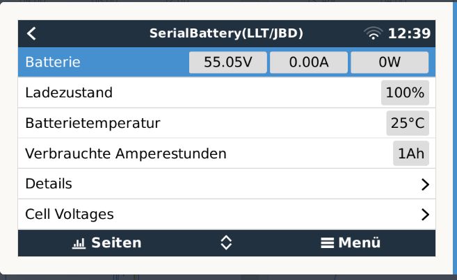
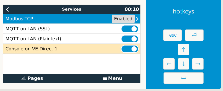
Serial Battery USB 0 current
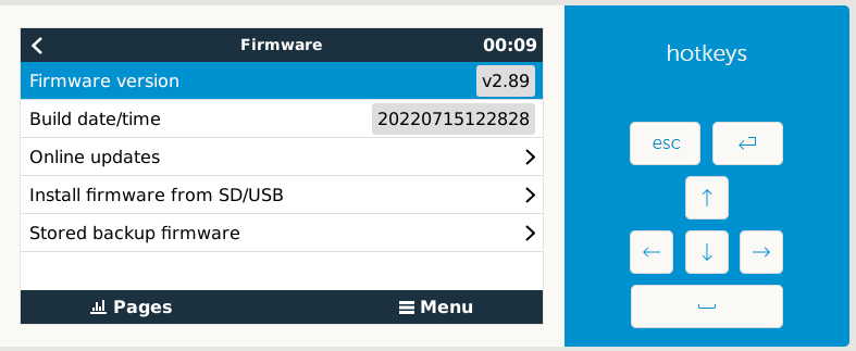
1665944160004.png

Serial battery USB1 current

1665944211738.png

USB 2 no JKBMS found ,

I'm new to linux but trying to learn quickly , - how do you tell which USBx is currently in use?

The radiation sensor is the imt-si-rs485tc


0 Likes 0 ·
1665943871250.png (125.8 KiB)
1665944160004.png (47.2 KiB)
1665944211738.png (70.7 KiB)
PeterM avatar image PeterM commented ·

repeated the VenusGX bootup and now cannot repeat the fault , although it can take up to 5 minutes for ration sensor to established connection

0 Likes 0 ·
Louis van der Walt avatar image Louis van der Walt PeterM commented ·
It seems that there was some port issue on USB1 at some stage. It could be an issue were the wiring did not make good contact or that one driver did not release the port fast enough. If that is solved now it should be fine. The GX device "learns" which driver works on each port and will test those first so the correct one can link up faster. So this should mitigate any further conflicts.


In Linux devices the tty ports and the phisical socket has no direct link. So when you add a new device the port used inside the linux instance could change from what it previously was.

If there is a new port activated, or if any driver exits from a port, then all the available drivers will be tested on that port to see which once works for the device that is connected there. So it is normal to see log files of drivers trying to connect, or connecting to a different port. From the log files this seems to be what happend here. Each device is now correctly connected to the 3 USB ports 0, 1 and 2

0 Likes 0 ·
elko avatar image
elko answered ·

Hello, everyone,

I use the current beta with my 16s Daly BMS.

How or where can I have the cell voltages displayed? The sol but recently go if I'm properly informed?

15 comments
2 |3000

Up to 8 attachments (including images) can be used with a maximum of 190.8 MiB each and 286.6 MiB total.

Louis van der Walt avatar image Louis van der Walt commented ·

If you have v0.14~1 then there is a Cell Voltages option under the battery details

1666509516621.png

0 Likes 0 ·
1666509516621.png (29.8 KiB)
elko avatar image elko Louis van der Walt commented ·

Leider nicht für mich.

1666516134719.png1666516174659.png

0 Likes 0 ·
1666516134719.png (20.5 KiB)
1666516174659.png (22.8 KiB)
Louis van der Walt avatar image Louis van der Walt elko commented ·

Perhaps the gui install did not run correctly for you.

Try to run the following in SSH and then check again.

> sh /data/etc/dbus-serialbattery/installqml.sh

0 Likes 0 ·
elko avatar image elko Louis van der Walt commented ·

Hello,

I ran the command over SSH and rebooted.

Now the VenusOS interface is no longer accessible. I can access it via SSH.

What can I do?


1666636033460.png
EDIT:

I ran the command one more time and suddenly the interface was available. Unfortunately, I still don't see the cell voltage.


1666636402733.png

0 Likes 0 ·
1666636033460.png (34.3 KiB)
1666636402733.png (41.4 KiB)
Louis van der Walt avatar image Louis van der Walt elko commented ·
Make sure you are running VenusOS V2.91

It's been tested well to work on that firmware.

0 Likes 0 ·
elko avatar image elko Louis van der Walt commented ·

I use v.2.92 is that the problem?
Will the ad also run under 2.92?

0 Likes 0 ·
Louis van der Walt avatar image Louis van der Walt elko commented ·
If the GUI had changes in 2.92 then that might be the reason. I'll have to check
1 Like 1 ·
elko avatar image elko Louis van der Walt commented ·

Hello,


I just updated v14 as well.

Unfortunately, the cell voltages are still not displayed to me.

1670097339504.png

0 Likes 0 ·
1670097339504.png (36.8 KiB)
rbeudel avatar image rbeudel elko commented ·

Hello, same with me.(Venus OS 2.92/v14) The MQTT Explorer shows under

N/b827eXXXXXd/battery/1/Voltages only values=0

I hope it will help, thank vou for the work


0 Likes 0 ·
elko avatar image elko Louis van der Walt commented ·

Haben sie eine Idee?

0 Likes 0 ·
rbeudel avatar image rbeudel elko commented ·
Ich leider nicht
0 Likes 0 ·
elko avatar image elko Louis van der Walt commented ·

@Louis van der Walt

I downgraded to 1.91 today.

But also here no cell voltage is displayed, Gtestet with your v0.14 beta1 and v.0.14.2.

I also used your above command.
sh /data/etc/dbus-serialbattery/installqml.sh

DalyBMS 16A

1672233591729.png

0 Likes 0 ·
1672233591729.png (36.8 KiB)
rbeudel avatar image rbeudel elko commented ·
Hello,

is the your BMS connected via UART or RS485? I read, I dont now where, only UART will deliver the cell voltages. My UART USB cable will not recognized by venus os and windows. It may be crashed.

0 Likes 0 ·
rbeudel avatar image rbeudel elko commented ·
Hello, today I build a UART Connection with a ftdi usb converter. Now is the battery cell voltage displayed. With RS485 no way.
0 Likes 0 ·
towatai avatar image towatai rbeudel commented ·

Unfortunately, I also just had to find out. I bought a Daly with Can/RS485 port to be able to use the Bluetooth dongle at the same time. In principle, it runs yes and it is also the lowest voltage and the highest of the cells displayed... just not all voltages of all cells. Is there any hope that this feature will be added? @Louis van der Walt If you can be helped in any way, please let me know


EDIT: This solution fixed it for me!
https://github.com/Louisvdw/dbus-serialbattery/issues/397

1 Like 1 ·
adamr100 avatar image
adamr100 answered ·
Hi,

I have 2 x Renogy Lithium batteries. For both to read out with this do I need 2 x the Renogy USB cables? I have tried with a couple of USB to RS485 leads but I suspect the FDMI or RS485 magic bit was missing. Or, is there something I need to do to have both batteries display?

Thank you in advance and thanks for your driver.

1 comment
2 |3000

Up to 8 attachments (including images) can be used with a maximum of 190.8 MiB each and 286.6 MiB total.

Louis van der Walt avatar image Louis van der Walt commented ·
You need a USB device per battery/BMS.
0 Likes 0 ·
shingsam avatar image
shingsam answered ·

Hi @Louis van der Walt can u help me to connect my battery Huawei ESM 48100.

I can read all info battery use USB to TTL use software. But i dnt know command to call BMS.

If u can, i will send you this software. Thankyou

2 comments
2 |3000

Up to 8 attachments (including images) can be used with a maximum of 190.8 MiB each and 286.6 MiB total.

Louis van der Walt avatar image Louis van der Walt commented ·
If we don't have the communications protocol documents it will be hard to implement. You will have to use serial logger software to try and capture the commands to be able to figure it out. Best would be if the manufacturer publish it for download.
0 Likes 0 ·
shingsam avatar image shingsam Louis van der Walt commented ·

Hi @Louis van der Walt, i find protocol documents for Huawei ESM. You can see or download here

https://support.huawei.com/enterprise/en/doc/EDOC1100239296

This my log when i connect app.

[INFO]: WritePort:_dc_03_00_42_00_02_76_92
[INFO]: ReadPort:_dc_03_04_00_00_00_08
[INFO]: WritePort:_dc_03_00_0b_00_01_e7_45
[INFO]: ReadPort:_dc_03_02_00_00
[INFO]: Get LiBatt State
[INFO]: WritePort:_dc_03_00_00_00_06_d7_45
[INFO]: ReadPort:_dc_03_0c_13_80_13_7d_00_00_00_3c_00_64_00_1d
[INFO]: WritePort:_dc_03_00_0a_00_01_b6_85
[INFO]: ReadPort:_dc_03_02_00_01
[INFO]: WritePort:_dc_03_00_12_00_0f_b7_46
[INFO]: ReadPort:_dc_03_1e_00_1c_00_1c_00_1c_00_1d_00_1d_00_1d_00_1d_00_1d_00_1d_00_1d_00_1d_00_1c_00_1c_00_1c_00_1c
[INFO]: WritePort:_dc_03_01_0f_00_01_a7_78
[INFO]: ReadPort:_dc_03_02_00_0f
[INFO]: WritePort:_dc_03_00_31_00_01_c7_48
[INFO]: ReadPort:_dc_03_02_ff_ff
[INFO]: WritePort:_dc_03_00_22_00_0f_b7_49
[INFO]: ReadPort:_dc_03_1e_0c_ff_0c_fd_0c_fd_0c_fd_0c_fd_0c_fd_0c_fd_0c_ff_0c_fd_0c_ff_0c_fd_0c_fd_0c_ff_0c_fd_0c_fd
[INFO]: WritePort:_dc_03_00_44_00_02_96_93
[INFO]: ReadPort:_dc_03_04_00_00_00_09
[INFO]: WritePort:_dc_03_01_07_00_01_26_ba
[INFO]: ReadPort:_dc_03_02_00_64
[INFO]: WritePort:_dc_03_01_01_00_01_c6_bb
[INFO]: ReadPort:_dc_03_02_01_05
[INFO]: WritePort:_dc_03_02_06_00_01_77_3e
[INFO]: ReadPort:_dc_03_02_00_00
[INFO]: WritePort:_dc_03_01_11_00_01_c7_7e
[INFO]: ReadPort:_dc_03_02_00_01
[INFO]: WritePort:_dc_03_02_11_00_0a_86_fd
[INFO]: ReadPort:_dc_03_14_45_58_32_31_37_30_30_30_30_39_33_31_ff_ff_ff_ff_ff_ff_ff_ff
[INFO]: WritePort:_dc_03_10_00_00_06_d3_85
[INFO]: ReadPort:_dc_03_0c_07_e6_00_0b_00_01_00_04_00_1b_00_37


0 Likes 0 ·
peregrines avatar image
peregrines answered ·

Hi!
Thank You so much for your great work!
I am replacing my JBD BMS now and want to buy JK BMS.

Is the following version (BT/RS485) working with Victron/ Serialbattery?
Or do I need the version with CANBUS also?

Thank You!


bildschirmfoto-2022-11-07-um-151544.png


2 comments
2 |3000

Up to 8 attachments (including images) can be used with a maximum of 190.8 MiB each and 286.6 MiB total.

Louis van der Walt avatar image Louis van der Walt commented ·

This JKBMS will work fine. You will use the port marked GPS either with the JKBMS 485 module and a 485 to USB converter, or just using a TTL to USB converter directly. [GND, Rx, Tx, Vbat]
(Don't connect Vbat unless you are using the JKBMS 485 module - it runs at the voltage from the battery)

PS. If you ask me I would not swop the JBD for a JKBMS. They are much the same.


1 Like 1 ·
peregrines avatar image peregrines Louis van der Walt commented ·
THANK YOU for your help Louis!

The reason I want to swap is the fact that one of my three JBD BMS failed on me today. Seems like the 300A Relais does not work anymore :(
Therefore I dont trust it anymore.

1 Like 1 ·
rambodk avatar image
rambodk answered ·

Hi Louis, first of all thank you for your excellent work on this driver.

I have installed driver on RPi4 Rev 1.5 Venus OS (Large v. 2.92) , having one Victron BMV-712and two 12V250A Daly BMS's connected. Everything worked great as a start, but after some hours the Victron BMV-712 suddenly started using the wrong driver causing below errors.

Is it possible to lock the Victron BMV-712 to NOT use the SerialBattery Sinowealth driver?

1668193377131.png

Thanks in advance.


1668193377131.png (188.3 KiB)
2 comments
2 |3000

Up to 8 attachments (including images) can be used with a maximum of 190.8 MiB each and 286.6 MiB total.

Louis van der Walt avatar image Louis van der Walt commented ·
Hi

At the moment the only way would be to edit the source of dbus-serialbattery.py and comment out the line for the Sinowealth with a # in front.

The next version will have an easier way as we moved the battery list to the utils.py and I am also working on a GUI to be able to edit the settings.

2 Likes 2 ·
rambodk avatar image rambodk Louis van der Walt commented ·
Hi Luis, thanks a lot for your fast answer. I will try to comment out thei Sinoealth Line in the dbus-serialbattery.py file.

Sounds great with new version including GUI to edit settings :-)

Thanks again.

1 Like 1 ·
PeterM avatar image
PeterM answered ·

Now have my 3 JK-BMS running beautifully and am finding tricky to work out which of the 3 BMS's is the Active one controlling DVCC ? Is there direct method to determine that ( that is without analysing the VRM portal for changes in charge current limits ) ? Well done to great battery driver Louis.

2 |3000

Up to 8 attachments (including images) can be used with a maximum of 190.8 MiB each and 286.6 MiB total.

towatai avatar image
towatai answered ·

Hi all, is there a way to use the driver on a Raspberry Pi to have a relay switch when a certain cell voltage is reached? About the total voltage I could realize it via the load output of my Victron Smartsolar charge controller, but this is rather suboptimal. I want to activate or deactivate one of the well-known active balancers automatically when a certain cell voltage is reached and not have it running permanently. Andy from Off-Grid Garage has recently published an interesting video about a JBD-BMS on steroids that can do exactly this.

1 comment
2 |3000

Up to 8 attachments (including images) can be used with a maximum of 190.8 MiB each and 286.6 MiB total.

PeterM avatar image PeterM commented ·
Lastest version 14.1 can do this
0 Likes 0 ·
Justin Tierney avatar image
Justin Tierney answered ·

Edit:

Found the answer

2 |3000

Up to 8 attachments (including images) can be used with a maximum of 190.8 MiB each and 286.6 MiB total.

luphi avatar image
luphi answered ·

Hello Louis,


the linear current limitation is really a great feature. I tested it today and noticed big jumps in the current due to jumps in the cell voltages. Is it possible to define a damping?

Lets say, using an average of the last n seconds for cell voltages.


Cheers,

luphi

2 |3000

Up to 8 attachments (including images) can be used with a maximum of 190.8 MiB each and 286.6 MiB total.

Justin Tierney avatar image
Justin Tierney answered ·

Anyone here have this working with EG4 LifePower4 12v/400ah batteries? (Cerbo, v2.92, usb provided by signature solar) I've run into a few issues, mostly user error which Louis was kind enough to point out and help resolve. Still having some issues, however. Was interested to see what others with this setup have seen to see what I could still be doing wrong. Thanks.

2 comments
2 |3000

Up to 8 attachments (including images) can be used with a maximum of 190.8 MiB each and 286.6 MiB total.

Eric Peetoom avatar image Eric Peetoom commented ·

Yes I got it working but I still can't use self consumption mode in the GX as soon as it sees grid voltage it turns off the invert mode.

0 Likes 0 ·
Justin Tierney avatar image Justin Tierney Eric Peetoom commented ·
Mind sharing your configuration? (What you did to make it work) I've tried and can't get mine to communicate. It seems like the BMS is different from the 24v/200ah battery, which the eg4 code seems to be based off of. Thanks.
0 Likes 0 ·
jacke avatar image
jacke answered ·

Hi I wanted to adjust the charge and discharge currents. For this I have adjusted utils.py unfortunately the default values are still displayed in Venus os. Does anyone have an idea?

# -*- coding: utf-8 -*-
import logging
import serial
from time import sleep
from struct import *
import bisect

# Logging
logging.basicConfig()
logger = logging.getLogger("SerialBattery")
logger.setLevel(logging.INFO)

# battery types
# if not specified: baud = 9600
battery_types = [
    {'bms' : "LltJbd"},
    {'bms' : "Ant", "baud" : 19200},
    {"bms" : "Daly", "address" : b"\x40"},
    {"bms" : "Daly", "address" : b"\x80"},
    {"bms" : "Jkbms", "baud" : 115200},
#    {"bms" : "Sinowealth"},
    {"bms" : "Lifepower"},
    {"bms" : "Renogy", "address": b"\x30"},
    {"bms" : "Renogy", "address": b"\xF7"},
    {"bms" : "Ecs", "baud" : 19200},
#    {"bms" : "MNB"},
]

# Constants - Need to dynamically get them in future
DRIVER_VERSION = 0.14
DRIVER_SUBVERSION = '.3' 
zero_char = chr(48)
degree_sign = u'\N{DEGREE SIGN}'

# Choose the mode for voltage / current limitations (True / False)
# False is a Step mode. This is the default with limitations on hard boundary steps
# True "Linear"    # New linear limitations by WaldemarFech for smoother values
LINEAR_LIMITATION_ENABLE = False

######### Cell Voltage limitation #########
# Description:
# Maximal charge / discharge current will be in-/decreased depending on min- and max-cell-voltages
# Example: 18cells * 3.55V/cell = 63.9V max charge voltage. 18 * 2.7V = 48,6V min discharge voltage
#          ... but the (dis)charge current will be (in-/)decreased, if even ONE SINGLE BATTERY CELL reaches the limits

# Charge current control management referring to cell-voltage enable (True/False).
CCCM_CV_ENABLE = True
# Discharge current control management referring to cell-voltage enable (True/False).
DCCM_CV_ENABLE = True

# Set Steps to reduce battery current. The current will be changed linear between those steps
CELL_VOLTAGES_WHILE_CHARGING         = [3.55, 3.50, 3.45, 3.30]
MAX_CHARGE_CURRENT_CV                = [   0,    2,  30,  60]

CELL_VOLTAGES_WHILE_DISCHARGING      = [2.70, 2.80, 2.90, 3.10]
MAX_DISCHARGE_CURRENT_CV             = [   0,    5,  30,  60]

######### Temperature limitation #########
# Description:
# Maximal charge / discharge current will be in-/decreased depending on temperature
# Example: The temperature limit will be monitored to control the currents. If there are two temperature senors,
#          then the worst case will be calculated and the more secure lower current will be set.
# Charge current control management referring to temperature enable (True/False).
CCCM_T_ENABLE = True
# Charge current control management referring to temperature enable (True/False).
DCCM_T_ENABLE = True

# Set Steps to reduce battery current. The current will be changed linear between those steps
TEMPERATURE_LIMITS_WHILE_CHARGING    = [55, 40,  35,   5,  2, 0]
MAX_CHARGE_CURRENT_T                 = [ 0, 28, 60, 60, 28, 0]

TEMPERATURE_LIMITS_WHILE_DISCHARGING = [55, 40,  35,   5,  0, -20]
MAX_DISCHARGE_CURRENT_T              = [ 0, 28, 60, 60, 28,   0]

# if the cell voltage reaches 3.55V, then reduce current battery-voltage by 0.01V
# if the cell voltage goes over 3.6V, then the maximum penalty will not be exceeded
# there will be a sum of all penalties for each cell, which exceeds the limits
PENALTY_AT_CELL_VOLTAGE  = [3.45, 3.55, 3.6]
PENALTY_BATTERY_VOLTAGE  = [0.01, 1.0, 2.0]  # this voltage will be subtracted


######### SOC limitation #########
# Description:
# Maximal charge / discharge current will be increased / decreased depending on State of Charge, see CC_SOC_LIMIT1 etc.
# The State of Charge (SoC) charge / discharge current will be in-/decreased depending on SOC.
# Example: 16cells * 3.45V/cell = 55,2V max charge voltage. 16*2.9V = 46,4V min discharge voltage
# Cell min/max voltages - used with the cell count to get the min/max battery voltage
MIN_CELL_VOLTAGE = 2.9
MAX_CELL_VOLTAGE = 3.45
FLOAT_CELL_VOLTAGE = 3.35
MAX_VOLTAGE_TIME_SEC = 15*60
SOC_LEVEL_TO_RESET_VOLTAGE_LIMIT = 90

# battery Current limits
MAX_BATTERY_CHARGE_CURRENT = 80
MAX_BATTERY_DISCHARGE_CURRENT = 100

# Charge current control management enable (True/False).
CCCM_SOC_ENABLE = True
# Discharge current control management enable (True/False).
DCCM_SOC_ENABLE = True

#charge current soc limits
CC_SOC_LIMIT1 = 98
CC_SOC_LIMIT2 = 95
CC_SOC_LIMIT3 = 91

#charge current limits
CC_CURRENT_LIMIT1 = 5
CC_CURRENT_LIMIT2 = MAX_BATTERY_CHARGE_CURRENT/4
CC_CURRENT_LIMIT3 = MAX_BATTERY_CHARGE_CURRENT/2

#discharge current soc limits
DC_SOC_LIMIT1 = 10
DC_SOC_LIMIT2 = 20
DC_SOC_LIMIT3 = 30

#discharge current limits
DC_CURRENT_LIMIT1 = 5
DC_CURRENT_LIMIT2 = MAX_BATTERY_DISCHARGE_CURRENT/4
DC_CURRENT_LIMIT3 = MAX_BATTERY_DISCHARGE_CURRENT/2

# Charge voltage control management enable (True/False).
CVCM_ENABLE = False

# Simulate Midpoint graph (True/False).
MIDPOINT_ENABLE = False

#soc low levels
SOC_LOW_WARNING = 20
SOC_LOW_ALARM = 10

# Daly settings
# Battery capacity (amps) if the BMS does not support reading it 
BATTERY_CAPACITY = 50
# Invert Battery Current. Default non-inverted. Set to -1 to invert
INVERT_CURRENT_MEASUREMENT = 1

# TIME TO SOC settings [Valid values 0-100, but I don't recommend more that 20 intervals]
# Set of SoC percentages to report on dbus. The more you specify the more it will impact system performance.
# TIME_TO_SOC_POINTS = [100, 95, 90, 85, 80, 75, 70, 65, 60, 55, 50, 45, 40, 35, 30, 25, 20, 15, 10, 5, 0]# Every 5% SoC
# TIME_TO_SOC_POINTS = [100, 95, 90, 85, 75, 50, 25, 20, 10, 0]
TIME_TO_SOC_POINTS = []# No data set to disable
# Specify TimeToSoc value type: [Valid values 1,2,3]
# TIME_TO_SOC_VALUE_TYPE = 1      # Seconds
# TIME_TO_SOC_VALUE_TYPE = 2      # Time string HH:MN:SC
TIME_TO_SOC_VALUE_TYPE = 3        # Both Seconds and time str "<seconds> [days, HR:MN:SC]"
# Specify how many loop cycles between each TimeToSoc updates
TIME_TO_SOC_LOOP_CYCLES = 5
# Include TimeToSoC points when moving away from the SoC point. [Valid values True,False] 
# These will be as negative time. Disabling this improves performance slightly.
TIME_TO_SOC_INC_FROM = False


# Select the format of cell data presented on dbus. [Valid values 0,1,2,3]
# 0 Do not publish all the cells (only the min/max cell data as used by the default GX)
# 1 Format: /Voltages/Cell# (also available for display on Remote Console)
# 2 Format: /Cell/#/Volts
# 3 Both formats 1 and 2
BATTERY_CELL_DATA_FORMAT = 1

# Settings for ESC GreenMeter and Lipro devices
GREENMETER_ADDRESS = 1
LIPRO_START_ADDRESS = 2
LIPRO_END_ADDRESS = 4
LIPRO_CELL_COUNT = 15

def constrain(val, min_val, max_val):
    if min_val > max_val:
        min_val, max_val = max_val, min_val
    return min(max_val, max(min_val, val))

def mapRange(inValue, inMin, inMax, outMin, outMax):
    return outMin + (((inValue - inMin) / (inMax - inMin)) * (outMax - outMin))

def mapRangeConstrain(inValue, inMin, inMax, outMin, outMax):
    return constrain(mapRange(inValue, inMin, inMax, outMin, outMax), outMin, outMax)

def calcLinearRelationship(inValue, inArray, outArray):
    if inArray[0] > inArray[-1]:    # change compare-direction in array
        return calcLinearRelationship(inValue, inArray[::-1], outArray[::-1])
    else:
 
        # Handle out of bounds
        if inValue <= inArray[0]:
            return outArray[0]
        if inValue >= inArray[-1]:
            return outArray[-1]
        
        # else calculate linear current between the setpoints
        idx = bisect.bisect(inArray, inValue)
        upperIN  = inArray[idx - 1]  # begin with idx 0 as max value
        upperOUT = outArray[idx - 1]
        lowerIN  = inArray[idx]
        lowerOUT = outArray[idx]            
        return  mapRangeConstrain(inValue, lowerIN, upperIN, lowerOUT, upperOUT)

def calcStepRelationship(inValue, inArray, outArray, returnLower):
    if inArray[0] > inArray[-1]:    # change compare-direction in array
        return calcStepRelationship(inValue, inArray[::-1], outArray[::-1], returnLower)
    
    # Handle out of bounds
    if inValue <= inArray[0]:
        return outArray[0]
    if inValue >= inArray[-1]:
        return outArray[-1]
    
    # else get index between the setpoints
    idx = bisect.bisect(inArray, inValue)
        
    return outArray[idx] if returnLower else outArray[idx-1]

def is_bit_set(tmp):
    return False if tmp == zero_char else True

def kelvin_to_celsius(kelvin_temp):
    return kelvin_temp - 273.1

def format_value(value, prefix, suffix):
    return None if value is None else ('' if prefix is None else prefix) + \
                                      str(value) + \
                                      ('' if suffix is None else suffix)

def read_serial_data(command, port, baud, length_pos, length_check, length_fixed=None, length_size=None):
    try:
        with serial.Serial(port, baudrate=baud, timeout=0.1) as ser:
            return read_serialport_data(ser, command, length_pos, length_check, length_fixed, length_size)

    except serial.SerialException as e:
        logger.error(e)
        return False


# Open the serial port
# Return variable for the openned port 
def open_serial_port(port, baud):
    ser = None
    tries = 3
    while tries > 0:
        try:
            ser = serial.Serial(port, baudrate=baud, timeout=0.1)
            tries = 0
        except serial.SerialException as e:
            logger.error(e)
            tries -= 1
            
    return ser

# Read data from previously openned serial port
def read_serialport_data(ser, command, length_pos, length_check, length_fixed=None, length_size=None):
    try:
        ser.flushOutput()
        ser.flushInput()
        ser.write(command)

        length_byte_size = 1
        if length_size is not None: 
            if length_size.upper() == 'H':
                length_byte_size = 2
            elif length_size.upper() == 'I' or length_size.upper() == 'L':
                length_byte_size = 4

        count = 0
        toread = ser.inWaiting()

        while toread < (length_pos+length_byte_size):
            sleep(0.005)
            toread = ser.inWaiting()
            count += 1
            if count > 50:
                logger.error(">>> ERROR: No reply - returning")
                return False
                
        #logger.info('serial data toread ' + str(toread))
        res = ser.read(toread)
        if length_fixed is not None:
            length = length_fixed
        else:
            if len(res) < (length_pos+length_byte_size):
                logger.error(">>> ERROR: No reply - returning [len:" + str(len(res)) + "]")
                return False
            length_size = length_size if length_size is not None else 'B'
            length = unpack_from('>'+length_size, res,length_pos)[0]
            
        #logger.info('serial data length ' + str(length))

        count = 0
        data = bytearray(res)
        while len(data) <= length + length_check:
            res = ser.read(length + length_check)
            data.extend(res)
            #logger.info('serial data length ' + str(len(data)))
            sleep(0.005)
            count += 1
            if count > 150:
                logger.error(">>> ERROR: No reply - returning [len:" + str(len(data)) + "/" + str(length + length_check) + "]")
                return False

        return data

    except serial.SerialException as e:
        logger.error(e)
        return False

211414820-38f255d8-2e64-47d0-9188-59162d9011f7.png


3 comments
2 |3000

Up to 8 attachments (including images) can be used with a maximum of 190.8 MiB each and 286.6 MiB total.

Mike avatar image Mike commented ·
Have you rebooted the device after editing the code?

That should fix it.

0 Likes 0 ·
Mike avatar image Mike Mike commented ·

Changes to code don‘t take effect until the system is rebooted

0 Likes 0 ·
larsea-dk avatar image larsea-dk commented ·
Hi

When I change the MAX_BATTERY_CHARGE_CURRENT to 80A it also doesn't work. I have to adjust the Current limits in the active sections i.e. if I have activated the Cell Voltage section, I also have to adjust the highest MAX_CHARGE_CURRENT CV to 80A to get it to work.

It might be a bug. I run the 14.3. Also the FLOAT_CELL_VOLTAGE is used as the max pack Voltage instead of the MAX_CELL_VOLTAGE. I don't know if this "bug" affect other areas.


BR, Lars

0 Likes 0 ·
Mike avatar image
Mike answered ·

a5715e1f-302e-4335-adbd-308da4830ed8.jpeg

Hi,

first of all thanks. Awesome work.

My installation is in my boat.

I have 5 batteries, each is 4 * 200ah CALB cells in series.

The 5 batteries are connected in parallel.

Out of the 20 cells, there are 2 cells that are lazy. Slow to change and fast to discharge. I will be replacing them.


However, the system works really well.

As it is a boat, usage varies. When it’s Not being used, the solar keeps the batteries full. When it is being used, the batteries cycle.

I have changed the utils code a little. I have put a storage max voltage and a storage float voltage that I can hash in or out. I don’t like keeping lifepo4 batteries at 100% when not being used.

Could you take a quick look, and let me know if you think this is a reasonable idea.


Secondly, as there are 5 bms, but only one is controlling, should I change the charge and discharge amps to 500?
they are 120a bms. Each bms will still limit the current to its own battery to 120a


here is my change to the code..


# -------- SOC limitation ---------

# Description:

# Maximal charge / discharge current will be increased / decreased depending on State of Charge, see CC_SOC_LIMIT1 etc.

# The State of Charge (SoC) charge / discharge current will be in-/decreased depending on SOC.

# Example: 16cells * 3.45V/cell = 55,2V max charge voltage. 16*2.9V = 46,4V min discharge voltage

# Cell min/max voltages - used with the cell count to get the min/max battery voltage

MIN_CELL_VOLTAGE = 2.9


######NORMAL
#MAX_CELL_VOLTAGE = 3.45

#FLOAT_CELL_VOLTAGE = 3.35

#####STORAGE
MAX_CELL_VOLTAGE = 3.40
FLOAT_CELL_VOLTAGE = 3.32


MAX_VOLTAGE_TIME_SEC = 15 * 60

SOC_LEVEL_TO_RESET_VOLTAGE_LIMIT = 90


# battery Current limits

MAX_BATTERY_CHARGE_CURRENT = 500.0

MAX_BATTERY_DISCHARGE_CURRENT = 500.


# Charge current control management enable (


2 |3000

Up to 8 attachments (including images) can be used with a maximum of 190.8 MiB each and 286.6 MiB total.

Mike avatar image
Mike answered ·

852692d0-5e70-45ba-be16-73d8e65dda58.jpeg

Hi,

first of all thanks. Awesome work.

My installation is in my boat.

I have 5 batteries, each is 4 * 200ah CALB cells in series.

The 5 batteries are connected in parallel.

Out of the 20 cells, there are 2 cells that are lazy. Slow to change and fast to discharge. I will be replacing them.


However, the system works really well.

As it is a boat, usage varies. When it’s Not being used, the solar keeps the batteries full. When it is being used, the batteries cycle.

I have changed the utils code a little. I have put a storage max voltage and a storage float voltage that I can hash in or out. I don’t like keeping lifepo4 batteries at 100% when not being used.

Could you take a quick look, and let me know if you think this is a reasonable idea.


Secondly, as there are 5 bms, but only one is controlling, should I change the charge and discharge amps to 500?
they are 120a bms. Each bms will still limit the current to its own battery to 120a


here is my change to the code..


# -------- SOC limitation ---------

# Description:

# Maximal charge / discharge current will be increased / decreased depending on State of Charge, see CC_SOC_LIMIT1 etc.

# The State of Charge (SoC) charge / discharge current will be in-/decreased depending on SOC.

# Example: 16cells * 3.45V/cell = 55,2V max charge voltage. 16*2.9V = 46,4V min discharge voltage

# Cell min/max voltages - used with the cell count to get the min/max battery voltage

MIN_CELL_VOLTAGE = 2.9


######NORMAL
#MAX_CELL_VOLTAGE = 3.45

#FLOAT_CELL_VOLTAGE = 3.35

#####STORAGE
MAX_CELL_VOLTAGE = 3.40
FLOAT_CELL_VOLTAGE = 3.32


MAX_VOLTAGE_TIME_SEC = 15 * 60

SOC_LEVEL_TO_RESET_VOLTAGE_LIMIT = 90


# battery Current limits

MAX_BATTERY_CHARGE_CURRENT = 500.0

MAX_BATTERY_DISCHARGE_CURRENT = 500.


# Charge current control management enable (

2 comments
2 |3000

Up to 8 attachments (including images) can be used with a maximum of 190.8 MiB each and 286.6 MiB total.

Louis van der Walt avatar image Louis van der Walt commented ·
the float settings is actually doing much of your storage stuff. If the battery is fully charged it will lower the battery voltage until it has been depleted a bit and then reset it.

If you manually want to lower the voltages like you have this is perfectly fine. Any cell that misbehave will still be balanced when it go over the balace threashold of the BMS.

0 Likes 0 ·
Mike avatar image Mike Louis van der Walt commented ·
Thanks!

what do you think I should put for the max charge and discharge current?

The bms is 120a, but there are 5 in parallel…

I have set the max charge and discharge to 500a.

My thinking was the bms would limit the current at 120a per battery and the Victron would then have an overall limit to 500 amps…


is this correct?


thanks

0 Likes 0 ·
sballhausen avatar image
sballhausen answered ·

Hello,

I also use these drivers on my Pi with an 8s Daly BMS. Thanks for that! Currently I only operate a Smart MPPT and a China inverter.

However, Venus OS does not show me if the battery is only charged with 50w. The MPPT states 50W in Venus, but according to the display nothing goes into the battery. I don´t knwo where it goes... The China Inverter is switched off.


If the battery is being discharged, charging will be displayed.

So exactly the wrong way around.


Is that because of a setting? Or is it the Daly? Or on Venus?


Best regards

Sebastian

1 comment
2 |3000

Up to 8 attachments (including images) can be used with a maximum of 190.8 MiB each and 286.6 MiB total.

rbeudel avatar image rbeudel commented ·

Hello,

do vou have in "/data/etc/dbus-serialbattery/utils.py" following line "# Invert Battery Current. Default non-inverted. Set to -1 to invert
INVERT_CURRENT_MEASUREMENT = -1" ? Take a look to the minus.

"Venus OS does not show me if the battery is only charged with 50w " In the pcmaster software of daly is a "current wave" field. There it is possible to change the minimum current. But in some firmware version this function is dead.

Best regards,

Ralf


0 Likes 0 ·
wolfgang-arndt avatar image
wolfgang-arndt answered ·

I have a big problem to get this to work stable.

I use a multiplus II gx. Venus os 2.92

I use this adapter with a jk bms

https://www.amazon.de/dp/B07RQ8TVRJ?ref=ppx_yo2ov_dt_b_product_details&th=1


In idle mode there is no problem, but when i start to charge the driver fails


n 30 21:36:11 nanopi user.info kernel: [ 3665.493167] usb 3-1: FTDI USB Serial Device converter now attached to ttyUSB0
Jan 30 21:36:14 nanopi user.err kernel: [ 3668.033304] usb usb3-port1: disabled by hub (EMI?), re-enabling...
Jan 30 21:36:14 nanopi user.info kernel: [ 3668.040062] usb 3-1: USB disconnect, device number 110
Jan 30 21:36:14 nanopi user.info kernel: [ 3668.054007] ftdi_sio ttyUSB0: FTDI USB Serial Device converter now disconnected from ttyUSB0
Jan 30 21:36:14 nanopi user.info kernel: [ 3668.062974] ftdi_sio 3-1:1.0: device disconnected
Jan 30 21:36:14 nanopi user.info kernel: [ 3668.499668] usb 3-1: new full-speed USB device number 111 using ohci-platform
Jan 30 21:36:14 nanopi user.info kernel: [ 3668.781684] usb 3-1: New USB device found, idVendor=0403, idProduct=6001, bcdDevice= 6.00
Jan 30 21:36:14 nanopi user.info kernel: [ 3668.790076] usb 3-1: New USB device strings: Mfr=1, Product=2, SerialNumber=3
Jan 30 21:36:14 nanopi user.info kernel: [ 3668.797388] usb 3-1: Product: FT232R USB UART
Jan 30 21:36:14 nanopi user.info kernel: [ 3668.801943] usb 3-1: Manufacturer: FTDI
Jan 30 21:36:14 nanopi user.info kernel: [ 3668.805790] usb 3-1: SerialNumber: AB0OH9VB
Jan 30 21:36:14 nanopi user.info kernel: [ 3668.815769] ftdi_sio 3-1:1.0: FTDI USB Serial Device converter detected
Jan 30 21:36:14 nanopi user.info kernel: [ 3668.822842] usb 3-1: Detected FT232RL
Jan 30 21:36:14 nanopi user.info kernel: [ 3668.832309] usb 3-1: FTDI USB Serial Device converter now attached to ttyUSB0
Jan 30 21:36:18 nanopi user.err kernel: [ 3672.468275] usb usb3-port1: disabled by hub (EMI?), re-enabling...
[ 3049.484634] ftdi_sio ttyUSB0: Unable to write latency timer: -62
[ 3049.491606] ftdi_sio 3-1:1.0: GPIO initialisation failed: -62
[ 3049.497664] usb 3-1: FTDI USB Serial Device converter now attached to ttyUSB0
[ 3049.505482] usb usb3-port1: disabled by hub (EMI?), re-enabling...
[ 3049.511737] usb 3-1: USB disconnect, device number 124
[ 3049.517392] ftdi_sio ttyUSB0: FTDI USB Serial Device converter now disconnected from ttyUSB0
[ 3049.526312] ftdi_sio 3-1:1.0: device disconnected
[ 3049.959866] usb 3-1: new full-speed USB device number 125 using ohci-platform
[ 3050.241689] usb 3-1: New USB device found, idVendor=0403, idProduct=6001, bcdDevice= 6.00
[ 3050.250001] usb 3-1: New USB device strings: Mfr=1, Product=2, SerialNumber=3
[ 3050.257180] usb 3-1: Product: FT232R USB UART
[ 3050.261619] usb 3-1: Manufacturer: FTDI
[ 3050.265463] usb 3-1: SerialNumber: AB0OH9VB
[ 3050.274767] ftdi_sio 3-1:1.0: FTDI USB Serial Device converter detected
[ 3050.281627] usb 3-1: Detected FT232RL
[ 3050.290461] usb 3-1: FTDI USB Serial Device converter now attached to ttyUSB0
[ 3051.866334] usb usb3-port1: disabled by hub (EMI?), re-enabling...
[ 3051.873108] usb 3-1: USB disconnect, device number 125
[ 3051.882878] ftdi_sio ttyUSB0: FTDI USB Serial Device converter now disconnected from ttyUSB0
[ 3051.891804] ftdi_sio 3-1:1.0: device disconnected
[ 3052.309645] usb 3-1: new full-speed USB device number 126 using ohci-platform
[ 3052.591634] usb 3-1: New USB device found, idVendor=0403, idProduct=6001, bcdDevice= 6.00
[ 3052.600111] usb 3-1: New USB device strings: Mfr=1, Product=2, SerialNumber=3
[ 3052.607349] usb 3-1: Product: FT232R USB UART
[ 3052.612432] usb 3-1: Manufacturer: FTDI
[ 3052.616343] usb 3-1: SerialNumber: AB0OH9VB
[ 3052.625819] ftdi_sio 3-1:1.0: FTDI USB Serial Device converter detected
[ 3052.632666] usb 3-1: Detected FT232RL
[ 3052.641121] usb 3-1: FTDI USB Serial Device converter now attached to ttyUSB0
2 |3000

Up to 8 attachments (including images) can be used with a maximum of 190.8 MiB each and 286.6 MiB total.

towatai avatar image
towatai answered ·

How does it behave in the meantime with the charging of two batteries that are connected in parallel, each with its own BMS, to the Victron? In my case, an Easysolar II GX.
I currently have a 24V/230Ah battery (connected to Daly BMS via RS485) installed which also works wonderfully. I now unexpectedly, an almost identical, came into the hands (This time CALB cells instead of EVE), same capacity, same BMS. Should now, for whatever reason, one battery is full earlier, the other does not continue to charge, because the charging voltage is reduced, right? How did you solve this most elegantly? A smartshunt is also available.

2 |3000

Up to 8 attachments (including images) can be used with a maximum of 190.8 MiB each and 286.6 MiB total.

derrick thomas avatar image
derrick thomas answered ·

@Louis van der Walt I am getting ready to replace my drop in LifePo4 batteries with 2 diy banks with Daly smart bms x2. Is this driver able to communicate to both Daly bms and combine them into one "virtual" battery bank? Or would I need to use the virtual battery bank thru node red?

2 |3000

Up to 8 attachments (including images) can be used with a maximum of 190.8 MiB each and 286.6 MiB total.

rickpickle avatar image
rickpickle answered ·

JBD BMS blocking charger from charging

Setting up a new system with 3,7v Lith Ion 18650 charged via Victron MPPT
I have a
Victron 30/100 MPPT
JBD BMS 60a
DIY battery 18650 lithium ion 7x3.7v 180ah 24v
RPI Venus OS large v2.9 with node red enabled
SerialBattery 0.14.3

I have changed Victron 100/30 MPPT settings using the Victron Connect
29.05v Absorption
29.05V Float
29.05v Equalization

I have changed the SerialBattery utils.py to

utils.py
MIN_CELL_VOLTAGE = 3.6
MAX_CELL_VOLTAGE = 4.1
FLOAT_CELL_VOLTAGE = 4.1
MAX_VOLTAGE_TIME_SEC = 15*60
SOC_LEVEL_TO_RESET_VOLTAGE_LIMIT = 90

I have set the JBD BMS to

FullChargeVol 4150
ChargeEndVol 3000
BalanceStartVoltage 4000

In Remote Console
DVCC set

sshot2.pngand REBOOTed

But there is something not allowing it to charge.

Victron Connect shows no reason, only showing

Status ON

When i look at the Remote Console Devicelist>SerialBattery JBD> IO

> Parameters
sshot3.png
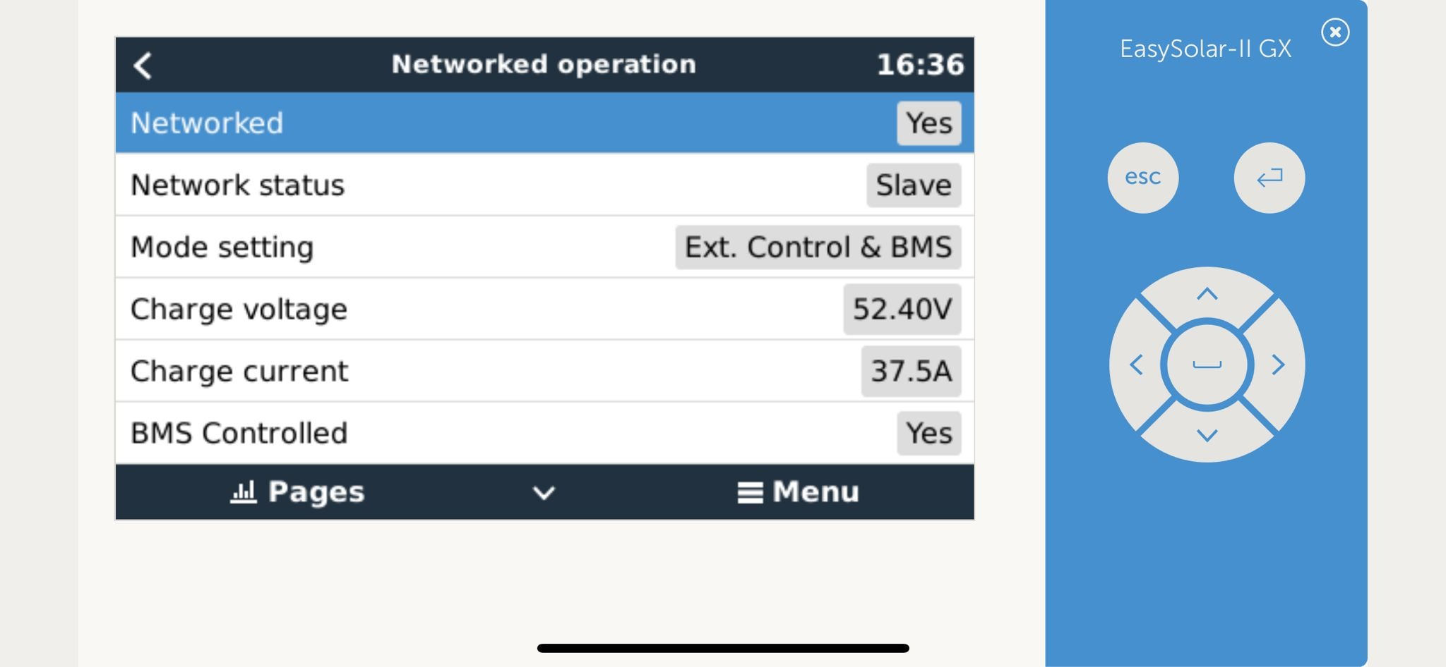
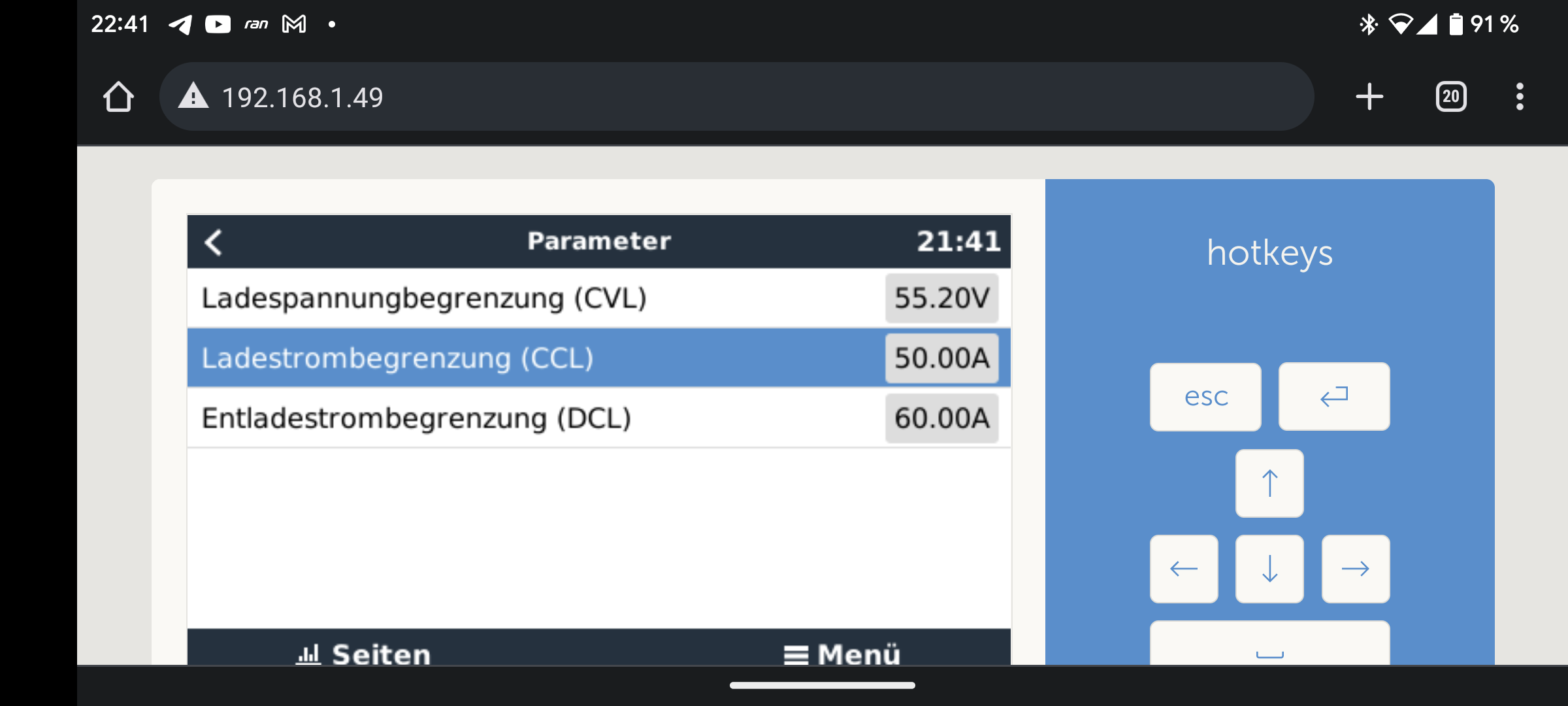
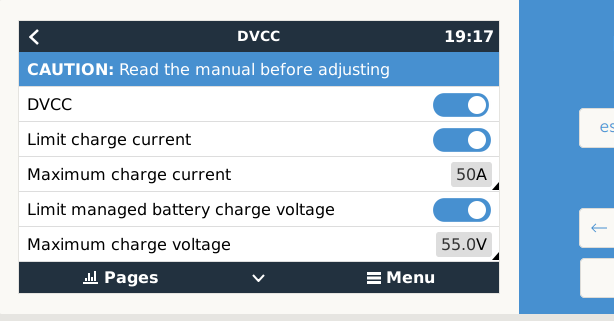
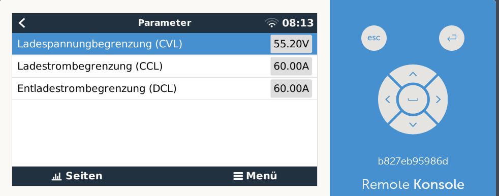
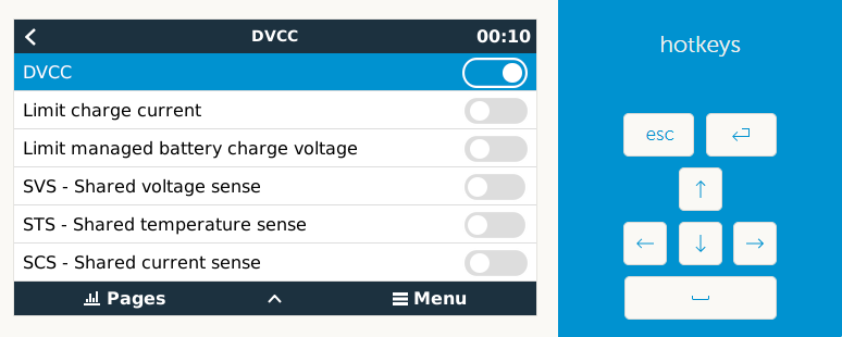
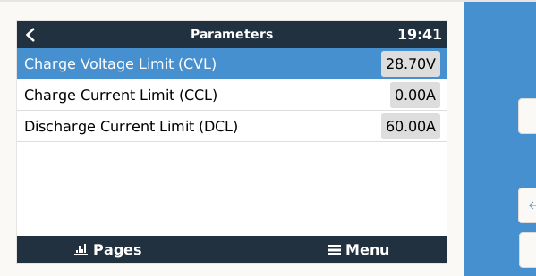
It shows the Allow to charge set to NO and ChargeCurrentLimit to 0.00A

If I disconnect the JBD BMS from the RPI it all charges up nicely. Its been taxing me on an off for over a week now so any ideas as to where i have gone wrong or what i could try would be gratefully appreciated.


sshot3.png (28.5 KiB)
sshot2.png (38.8 KiB)
1 comment
2 |3000

Up to 8 attachments (including images) can be used with a maximum of 190.8 MiB each and 286.6 MiB total.

rickpickle avatar image rickpickle commented ·

I have since changed the CCCM and DCCM in utils.py and the charge controller is now allowing charge.

######### Cell Voltage limitation #########
# Description:
# Maximal charge / discharge current will be in-/decreased depending on min- an>
# Example: 18cells * 3.55V/cell = 63.9V max charge voltage. 18 * 2.7V = 48,6V m>
# ... but the (dis)charge current will be (in-/)decreased, if even ONE>

# Charge current control management referring to cell-voltage enable (True/Fals>
CCCM_CV_ENABLE = False
# Discharge current control management referring to cell-voltage enable (True/F>
DCCM_CV_ENABLE = False


0 Likes 0 ·
Ulf Schneider avatar image
Ulf Schneider answered ·

Hello, Luis,

please call out the name and directory where i can find the config file inside installed package of the BMS driver at Venus V2.93 for raspberry Pi2 !

I have to change the current limits ! I need 75A charging current and 150A discharging current!

But Your driver allows only 50/ 60A!

Best regards, Ulf Schneider


2 |3000

Up to 8 attachments (including images) can be used with a maximum of 190.8 MiB each and 286.6 MiB total.

Ulf Schneider avatar image
Ulf Schneider answered ·

Hello, Louis,

i installed Your driver at Venus OS V2.93 at raspberry Pi3. It works well, but I have to change the current limits. Your driver allows only 50A charging current and 60A discharging current. But i need 75A charging current and 150A discharging current!

Ist there anywhere a config file to find and to change it by ssh?

Best regards and thanks for effort.

Ulf Schneider

anlage.jpg


anlage.jpg (5.1 MiB)
2 |3000

Up to 8 attachments (including images) can be used with a maximum of 190.8 MiB each and 286.6 MiB total.

Ulf Schneider avatar image
Ulf Schneider answered ·

Hello, Louis,

i installed Your serial driver at RaspberryPi3 under Venus OSV2.93. It works well. But I have to change the current limit values to 75A charging and 150A discharging. How can i do this? Is there anywhere a config file that can be edited by ssh with nano? anlage.jpg

Thanks for effort, best regards, Ulf Schneider


anlage.jpg (5.1 MiB)
2 |3000

Up to 8 attachments (including images) can be used with a maximum of 190.8 MiB each and 286.6 MiB total.

bonzai avatar image
bonzai answered ·

Hallo, Sie müssen die utils.py bearbeiten


sorry, it is new. You must edit the default_config.ini

2 |3000

Up to 8 attachments (including images) can be used with a maximum of 190.8 MiB each and 286.6 MiB total.

Ulf Schneider avatar image
Ulf Schneider answered ·

Recht vielen Dank!

Die utils.py konnte ich nämlich auch nicht finden!

Werde mich heute Abbend mit dem nano Editor daran versuchen und morgen hoffentlich über den Erfolg berichten können.

2 |3000

Up to 8 attachments (including images) can be used with a maximum of 190.8 MiB each and 286.6 MiB total.

bonzai avatar image
bonzai answered ·

Dit utils.py muss aber trotzdem vorhanden sein, sonst ist was falsch gelaufen. nur wird diese nicht mehr bearbeitet sondern die default_config.ini

2 |3000

Up to 8 attachments (including images) can be used with a maximum of 190.8 MiB each and 286.6 MiB total.

Ulf Schneider avatar image
Ulf Schneider answered ·

Ich finde die Verzeichnisse und files einfach nicht. Ich habe unter der letzten V2.93 mit diesem Kommando den Batterietreiber online nachinstalliert:

wget https://raw.githubusercontent.com/Louisvdw/dbus-serialbattery/master/etc/dbus-serialbattery/installrelease.sh

Der Treiber lief auf Anhieb: treiber-lauft.jpg

Aber im Setup Helper warr er weder unter aktiven noch unter inaktiven packages sichtbar:

im-install-helper-nicht.jpg

Dann habe ich im Verzeichnis /data/etc/

nach dbus-serialbattery/utils.py gesucht und nicht gefunden:


dbus-1.jpg

Wohl aber ein ähnlich klingendes Verzeichnis dbus-1.

Darunter befinden sich nur diese 3 files:

systemconf.jpg

Aber wenn ich mit dem nano editor auf die system.conf zugreifen will, bekomme ich diese Warnung:

nano-systemconf.jpg


Ich komme einfach als Linux Laie nicht weiter und bitte um Hilfe.

Wenn mir jemand per Team Viewer helfen könnte, das Konfigurationsverzeichnis zu finden, würde ich das auch gerne honorieren wollen.

Ulf Schneider


treiber-lauft.jpg (31.4 KiB)
dbus-1.jpg (48.8 KiB)
systemconf.jpg (54.1 KiB)
nano-systemconf.jpg (80.1 KiB)
2 |3000

Up to 8 attachments (including images) can be used with a maximum of 190.8 MiB each and 286.6 MiB total.

derrick thomas avatar image
derrick thomas answered ·

You will not find this under package manager, that has not been incorporated that way yet. The following typed into ssh terminal should get you there if everything was installed correctly

Vi /data/etc/dbus-serialbattery/utils.py

2 |3000

Up to 8 attachments (including images) can be used with a maximum of 190.8 MiB each and 286.6 MiB total.

Ulf Schneider avatar image
Ulf Schneider answered ·

Danke, ich war einfach im falschen /etc Verzeichnis. Es gibt mehrere gleichnamige in verschiedenen Oberverzeichnissen. Ich habe die utils.py gefunden, die Stromlimits mit nano auf 70A und 100A geändert, reboot gemacht, kontrolliert, daß die neuen Werte in utils.py auch drinstehen, aber es ändert sich Nichts.

Das sehe ich an diesem Limit Fenster im VRM Portal:

BMS Charge and Discharge Limits - SerialBattery(LLT/JBD) [1]

CVL - Charge Voltage Limit (V) CCL - Charge Current Limit (A) DCL - Discharge Current Limit (A)

Es zeigt die alten Limits 50 und 60A.

Bonzai gab mir diesen Hinweis:

1681410026690.png

bonzai beantwortet · Apr 02 2023 um 7:41 PM


Hallo, Sie müssen die utils.py bearbeiten

sorry, it is new. You must edit the default_config.ini

_______________________________________________________

Aber die default_config.ini finde ich nicht unter diesem Pfad.

Unter welchem kompletten Pfad kann ich die default_config.ini finden?

Danke für die Mühe mit einem DAU. (DAU = dümmster anzunehmender user).

Ulf


1681410026690.png (1.6 KiB)
2 |3000

Up to 8 attachments (including images) can be used with a maximum of 190.8 MiB each and 286.6 MiB total.

bonzai avatar image
bonzai answered ·

Schauen Sie mal in die Remote Console bei dem Treiber, ganz unten Parameter. Dort müßte die Änderung zu sehen sein.

empfehle ich https://github.com/Louisvdw/dbus-serialbattery/issues/421 .

Die ist momentan die neueste Weiterentwicklung


screenshot-20230413-213054-chrome.jpg


2 |3000

Up to 8 attachments (including images) can be used with a maximum of 190.8 MiB each and 286.6 MiB total.

Ulf Schneider avatar image
Ulf Schneider answered ·

Leider kein Erfolg. Ich habe mit dem Befehl "find" im ganzen Raspberry kein Configfile mit dem Namen "default_config.ini" gefunden:

keine-default-configini.jpg

Mit dem gleichen Befehl konnte ich die utils.py unter dem Pfad /data/etc/dbus-serialbatt/utils.py die utils.py finden und darin mit nano die Lade- und Entladelimits hochsetzten. Ich habe nach reboot auch nochmal kontrolliert, ob die Änderungen auch wirklich übernommen wurden:


utilspy-changed.jpg


Trotzdem sehe ich auf der GUI unter Parameter nicht die geänderten Limits:

gui-parameter.jpg 
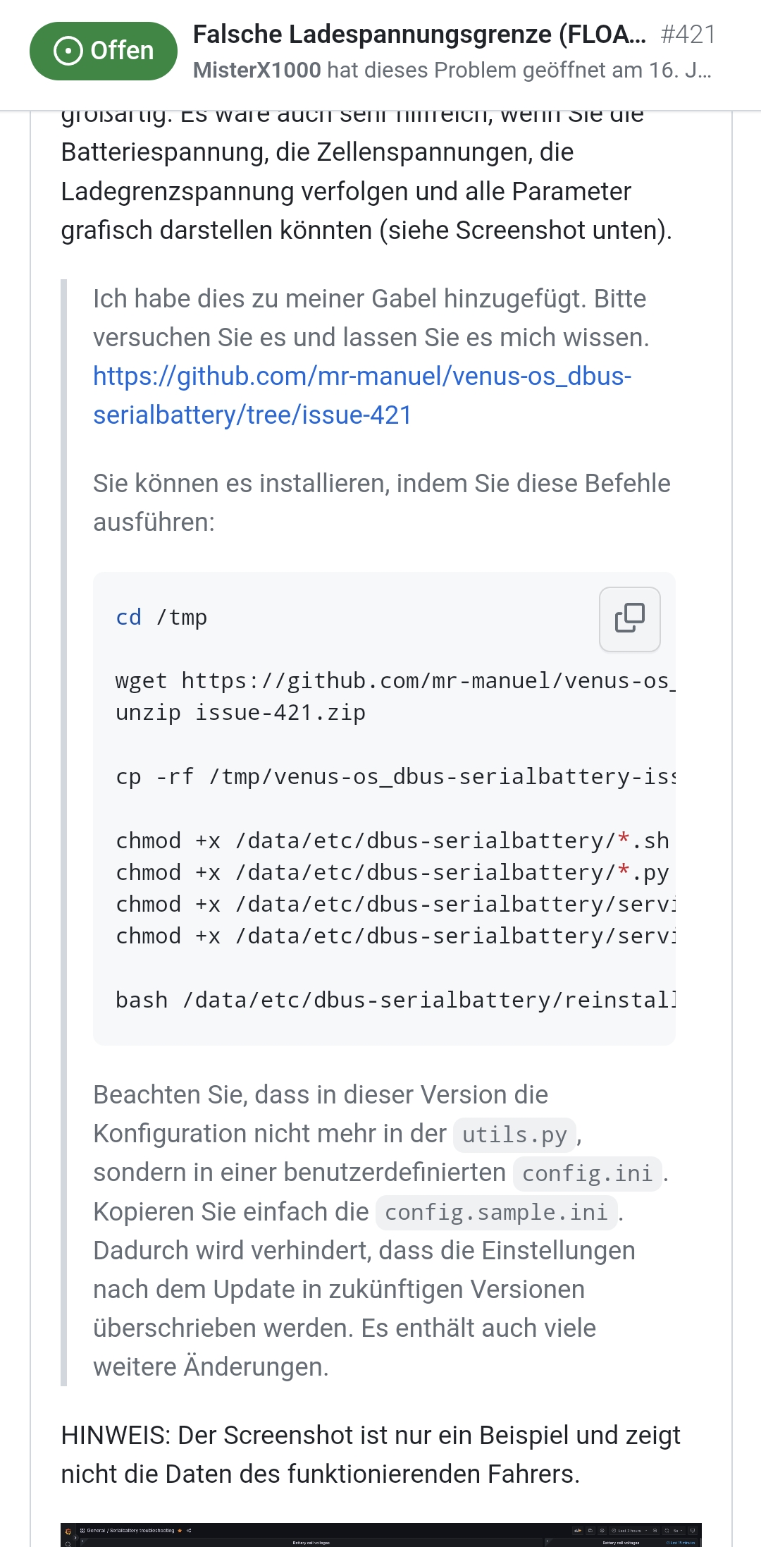
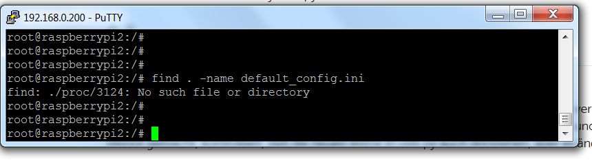
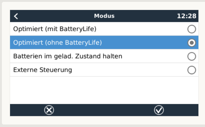
Was kann man als Linux Laie mit nur rudimentalen Programmierkenntnissen noch tun?
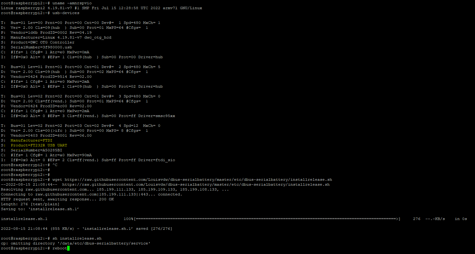
Ulf


2 |3000

Up to 8 attachments (including images) can be used with a maximum of 190.8 MiB each and 286.6 MiB total.

Related Resources