question

jw1971 avatar image
jw1971 asked

How to disconnect battery in an emergency when using Lynx power system?

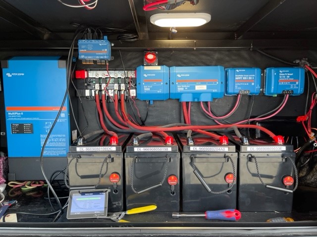
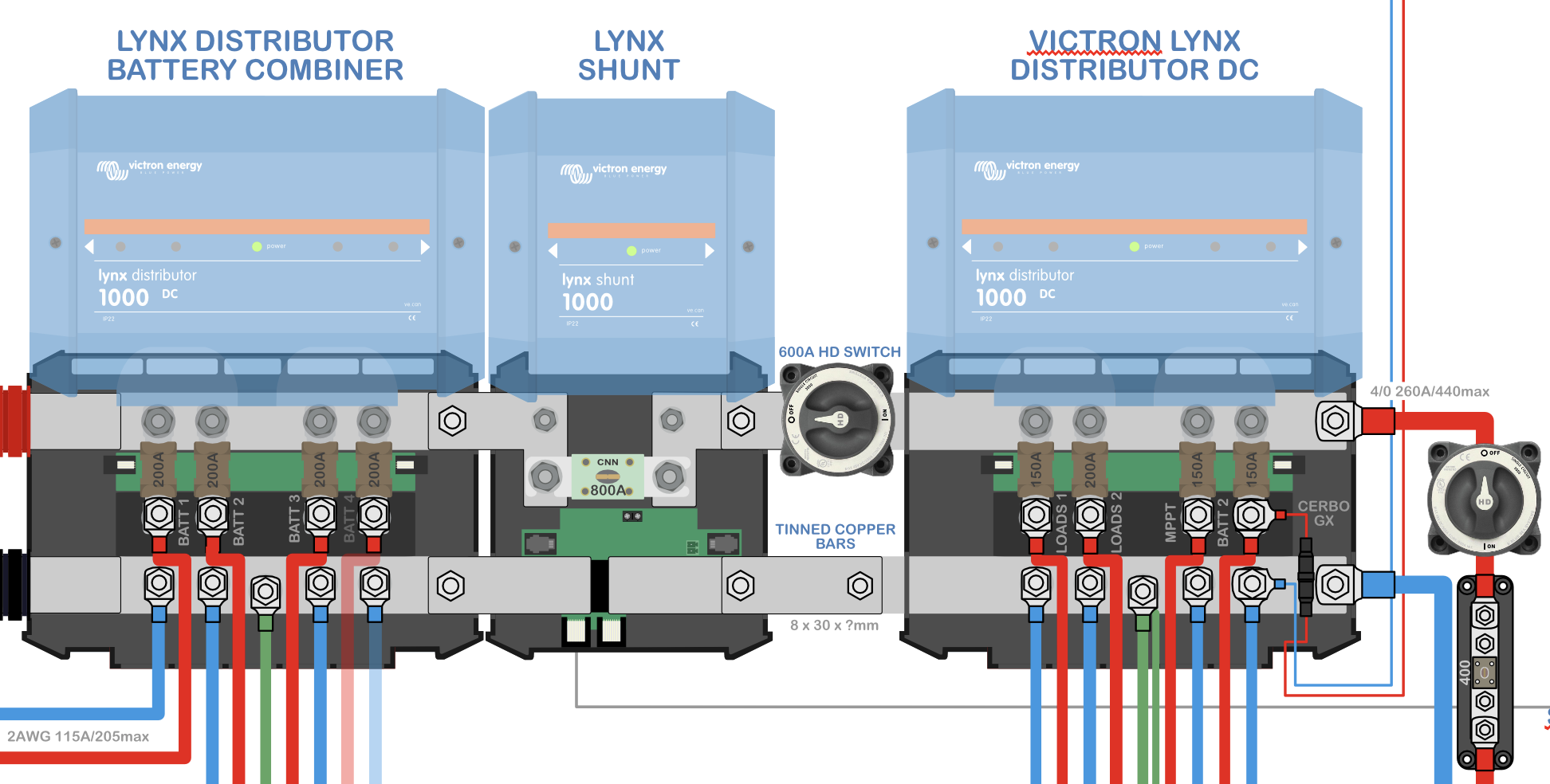
I am planning a setup to use a Lynx Distributor for batter input, then Lynx Shunt, and another Lynx Distributor to the loads. Management will be a Cerbo.

Question: In such a configuration what are people doing for emergency battery disconnect switching?

lynx shunt
1 comment
2 |3000

Up to 8 attachments (including images) can be used with a maximum of 190.8 MiB each and 286.6 MiB total.

duswami avatar image duswami commented ·

@jw1971 It's pretty simple, you have a bat disconnect on the positive wire running between the bat, to the pos bus bar on the Lynx Dist. You fuse the battery in the Lynx. The Shunt goes on the negative wire, between the bat and the lynx neg bus bar. If you need to disconnect the bats, you simply use the disconnect switch. However, as a rule of thumb, make sure you test for voltage on the at the Lynx before you work on it, voltage discharge can take a minute especially if the Mutli was previously running, and make sure you also have a PV disconnect between the Panels and the MPPT. I always check voltage at the bus bar as a matter of safety.

0 Likes 0 ·
10 Answers
Tony avatar image
Tony answered ·

Well I tried this and it seems to be working. I haven't installed it in my RV yet but it seems to work on the bench. Ill let everyone know how well it works when its installed.

Thanks

T


2 |3000

Up to 8 attachments (including images) can be used with a maximum of 190.8 MiB each and 286.6 MiB total.

Tony avatar image
Tony answered ·

Its installed and works fine!!

2 |3000

Up to 8 attachments (including images) can be used with a maximum of 190.8 MiB each and 286.6 MiB total.

seb71 avatar image
seb71 answered ·

I wrote a longer answer, but it was rejected (I had some links in it with examples).


Instead of Lynx Distributor, use a Lynx Power In (or nothing for a single battery).

Then use a NH switch fuse disconnector for the positive cable from the battery (with a short as possible cable from the battery to the NH fuse).


Also, you can skip the Lynx Shunt and use a cheaper SmartShunt instead (some DIY required).

3 comments
2 |3000

Up to 8 attachments (including images) can be used with a maximum of 190.8 MiB each and 286.6 MiB total.

jesseafuchs avatar image jesseafuchs commented ·

I was hoping on using the same system and had this same question!

Would the main difference between the smart shunt and the lynx shunt be the freedom to disconnect loads as you have described? John C suggested the Smart shunt to me as well and I was just going to weigh the pros and cons. Im a sucker for the clean install of the lynx system.

0 Likes 0 ·
seb71 avatar image seb71 jesseafuchs commented ·

Take a look here for details (if you haven't already).


Disconnecting loads have nothing to do with Lynx Shunt or SmartShunt.


Lynx Shunt would be installed between two Lynx Distributors or between a Lynx Distributor and a Lynx Power In or just with one Lynx Distributor when having a single battery.

Same with a SmartShunt, but in this case you would need to do some DIY work and won't look as nice. You can also DIY the entire busbar part (and no loger get a Lynx Disttributor/Lynx Power In).


SmartShunt uses VE.Direct for the connecting cable to the GX device and has Bluetooth.

Lynx Shunt uses VE.Can for the connecting cable to the GX device.


The SmartShunt is much cheaper than Lynx Shunt.

0 Likes 0 ·
jesseafuchs avatar image jesseafuchs seb71 commented ·

Thanks!

So far i am only in the planning stage so I have some freedom to make all the changes. I'm going to look into somehow using the lynx system but incorporating some custom buss work and battery protect or cyrix between the shunt and the distribution.

Cheers

0 Likes 0 ·
childcarepro avatar image
childcarepro answered ·

I'm puzzling this out too. I'm leaning away from busbars toward a Lynx system, not just for cleanness but for robustness (1000 amps!), minimizing cabling/joints and points of failure. In my system I'm going to use a Lynx Power In to connect 3 12V LiFePO4 batteries in parallel, connect that to a Lynx Shunt, then to a Lynx Distributor for the load side. While the Lynx Shunt covers the shunt function and the fusing nicely, I don't see a super clean way to add an emergency battery disconnect.

I may have to insert a battery disconnect switch between the Lynx Shunt and the Lynx Distributor using solid copper battery busbars to minimize cabling and joints. It will break up the clean lines but add minimal points of failure.

Any other thoughts are welcome. Thank you.

Just a feature request for Victron: Lynx Shunt 2.0 should have a battery disconnect function right on the outer case.

2 comments
2 |3000

Up to 8 attachments (including images) can be used with a maximum of 190.8 MiB each and 286.6 MiB total.

klim8skeptic avatar image klim8skeptic ♦ commented ·

NH1 hrc fuses/holders similar to THIS give fusing and disconnection for 3 poles at once.

0 Likes 0 ·
childcarepro avatar image childcarepro klim8skeptic ♦ commented ·

Thank you, that looks like just what I need, but a bit hard to source. I'll keep looking, as your link is from an Aussie company and I'm in the US. I think @seb71 mentioned something like it, but similarly hard to find, at least online.

The other problem: it's a whole new category of thing I have to figure out how to implement.

0 Likes 0 ·
Tony avatar image
Tony answered ·

I'm going to build my system exactly the same. Lynx Distro+Shunt+Distro All my batteies on the one side and the loads on the other.

Could you just add a Switch on the Shunt positive side instead of a Fuse? Mount a switch right above the shunt and cut away some of the plastic from the top. Then just run some cable to both sides to the Shunt Positive terminals. Still very clean and you can disconnect In Between. Anyone know weather this would work?

Thanks


lynxshunt.jpg


lynxshunt.jpg (121.9 KiB)
2 |3000

Up to 8 attachments (including images) can be used with a maximum of 190.8 MiB each and 286.6 MiB total.

Tony avatar image
Tony answered ·

lynx-shunt-2.jpg
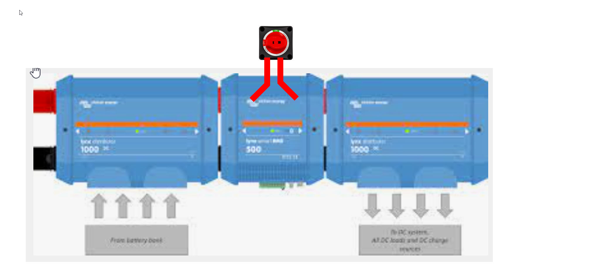
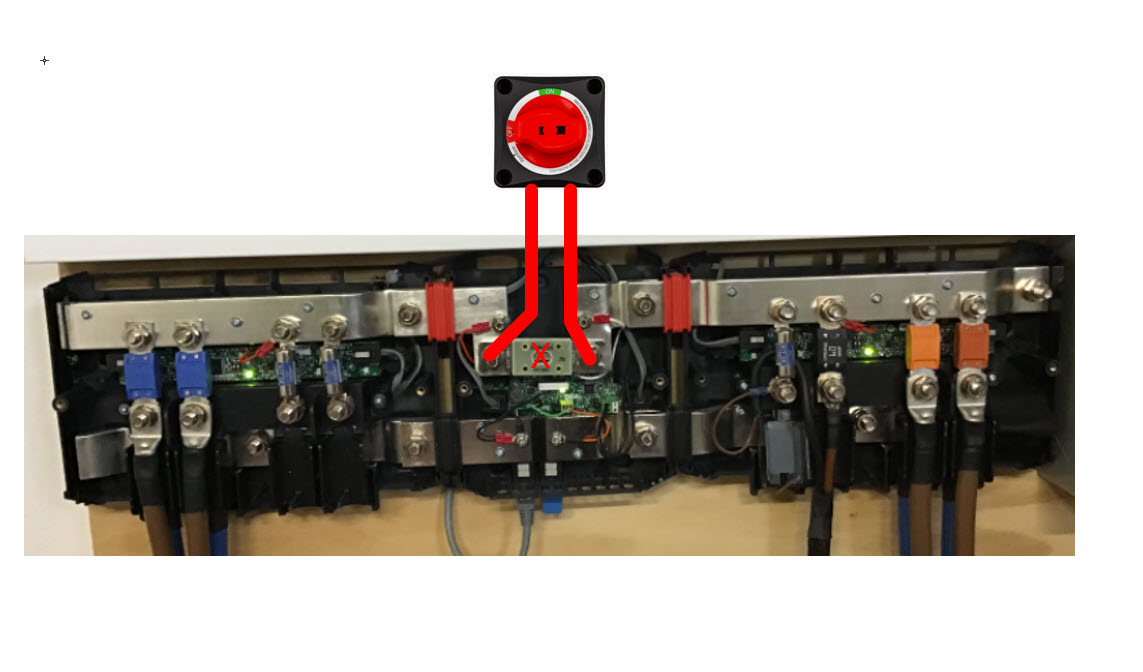
As long as the batteries are on the left side Distro the shunt would always have power. And shouldn't loose the SOC. It would just be like a blown fuse when you turn it off!!


lynx-shunt-2.jpg (82.2 KiB)
2 |3000

Up to 8 attachments (including images) can be used with a maximum of 190.8 MiB each and 286.6 MiB total.

Tony avatar image
Tony answered ·

tk-victron.jpg

My system with the Disconnect Installed.


tk-victron.jpg (87.3 KiB)
8 comments
2 |3000

Up to 8 attachments (including images) can be used with a maximum of 190.8 MiB each and 286.6 MiB total.

tongslee avatar image tongslee commented ·
wouldn't this setup bypass the fuse in the lynx shunt?
0 Likes 0 ·
ponzoa avatar image ponzoa tongslee commented ·
Nice set up there in the photo Tony. The main recomendation I would make is that your cables between the Lynx Distributor and the batteries should be the same lenghth to ensure even draw and charge and loss and voltage etc.


If you wanted to fuse this, you could add a fuse holder between one of the legs between the SHunt and the switch, and just a longer cable for the other leg.


1 Like 1 ·
tongslee avatar image tongslee tongslee commented ·
NVM, I just noticed you have fues with each battery. My bad.
0 Likes 0 ·
Jacob Stamm avatar image Jacob Stamm tongslee commented ·
Yes, Tony's is one of the cleanest solutions I've stumbled upon but you are correct in the current config this solution will forego the larger ANL fuse in the shunt. As you pointed out each battery still has an independent MEGA fuse at the distributor. I plan on modeling this for use on a boat. Electrical wiz I am not but I would like to attempt to expand on his design and retain the ANL somehow...
0 Likes 0 ·
childcarepro avatar image childcarepro commented ·

Nice solution! Seems to be the least non-ideal of the non-ideal solutions d/t the only (but major) flaw in the Lynx system.

IMHO the lynx shunt should have the option of either a shutoff switch or a fuse at the fuse holder location. I believe with a battery combiner having a fuse on each battery, seems to me the fuse in the shunt is redundant.

To keep the + and – paths the same length, this is another solution I am contemplating. Or the simplest solution is to just go with a Smart Shunt rather than the Lynx Shunt and a jumper cable for the negative leg.screen-shot-2022-05-15-at-13256-pm.png

0 Likes 0 ·
johnsmith avatar image johnsmith childcarepro commented ·

The fuse in the Shunt is not redundant, I presume Victron designed it this way for the following reason.


If you have a lynx power in or distributer used for battery strings you would need a main fuse for discrimination. The following is a real life example of what would happen.


Let’s say you have 4 batteries with 100A fuses on each battery string before your power in/ distributer . This gives a combined potential current draw of 400A before one of the fuses pops. I won’t get too technical and bring in fuse curves and let through currents ,let’s just say a 100a fuse blows at 100amps even though this is not true.

Now if we have a fault current of 410 amps on the lynx shunt one of the string 100a fuses will blow depending on the resistance path along the bus bar, then when this fuse blows the other three fuses can now only supply 300A in total, so sequentially all 3 fuses will immediate blow.


The reason for the main fuse in the shunt is to open when the potential continuous current draw and the possible over current in a branch circuit fault along with a short circuit fault current exceeds the combined string fuse total, while still protecting the bus bar off course.. Let’s ignore all the calcs and just say that your main fuse needs to be 75% of your combined string fuses. So 300A main fuse. This then allows the fault current of 410A to blow the 300A main fuse without blowing all your string fuses sequentially.

This is how we would design circuits for transformers and mains into distribution. It’s the same concept.

So if you have strings of batteries or more than one battery In Parallel on your incoming then you need a main fuse. On bigger installs you would have multiple main fuses in parallel, all summing to less that your incoming fuses from the battery strings.


Stay safe.

2 Likes 2 ·
rainer avatar image rainer childcarepro commented ·

This looks like a good solution for me because I am not using the Lynx shunt.
The 600 A HD switch shown in the drawing has M12 terminals,
which is larger than the M8 busbar terminals connecting the Lynx devices.
The 275A battery switch offered from Victron has 9.53mm terminal diameter,
which would fit better if the current rating is sufficient.
Can you connect the switch directly with nuts and screws with the busbar terminals from the Lynx devices?

0 Likes 0 ·
blindbadger avatar image blindbadger commented ·
Did you have to cut the cover to allow the cables out?
0 Likes 0 ·
jw1971 avatar image
jw1971 answered ·

The only remaining issue is the parasitic draw from the Lynx Shunt itself. It is very small but ideally you would have a disconnect in front of it to totally shut it down when you want the system off.

2 |3000

Up to 8 attachments (including images) can be used with a maximum of 190.8 MiB each and 286.6 MiB total.

Armel Peel avatar image
Armel Peel answered ·

Ahoy about a year later! Not all good news unfortunately.

Ok I have a problem with the "accepted answer." My first problem is "removing the fuse and putting a battery switch there" is incorrect, dangerous, and definitely not up to code. The fuses are there to protect your equipment and your life. You should not remove these for any reason, in fact doing so is a code violation (fines/confiscation) and could be in fact illegal considering this could cause death.

The second problem is in the accepted answer picture from Tony, he shouldnt be using a lynx distributer instead of a power in. I thought about this too when I first started studying the lynx distribution system, but the reason is because fuses belong on the battery terminals themselves. On the busbar is better than nothing I suppose. But this is not the correct solution, the real solution is to put a correctly sized MRBF (Marine Rated Battery Fuse) on the positive terminal of each battery.

ABYC code clearly states "The ABYC requirement is for a battery bank fuse to be within 7 wire inches of the battery bank." The reason is if you put fuses that far AWAY from the batteries, you arent using MRBF fuses on the terminal. And why the hell arent you using MRBF fuses on the terminal? If you didnt know take a hint. If something goes wrong you want the fuses to blow at the battery terminal so you dont have kill wires full of current whipping all around your battery compartment.

Those are my problems with the accepted answer. The closest solution I have found is this. You need to connect the lynx shunt to the CerboGX using the VE.can bus. Because Tony actually HAS a CerboGX in the picture I have no idea why he would not use it. Basically connect the lynx shunt to the CerboGX using the VE.can bus. Then you can connect to it from the mounted Touch 50 screen, a mobile phone, tablet, or computer. From the touch screen you can use the CerboGX as a soft switch and shut down the batteries (via the shunt I think), the inverter, and any other equipment connected. This solution was discussed here using a lynx BMS (instead of a lynx shunt) and I THINK it applies here.

https://community.victronenergy.com/questions/139340/main-battery-switch-before-lynx-distribution-syste.html

Can anyone with a CerboGX confirm this? If it works this would be much superior to a battery switch because you will need battery and device monitoring anyway.

The cost of a CerboGX and the Touch 50 is around half the cost of an iphone. I consider that cost reasonable. I dont believe anyone setting up a serious electrical system should cut that corner.


1 comment
2 |3000

Up to 8 attachments (including images) can be used with a maximum of 190.8 MiB each and 286.6 MiB total.

blindbadger avatar image blindbadger commented ·

Discussed here: https://community.victronenergy.com/questions/243332/battery-disconnect-switch.html


The lynx shunt doesn’t have a contractor to do a disconnect like the bms. Someone could use the bms as a VERY expensive shunt and disconnect and ignore the bms features, but that seems cost prohibitive.

In theory, someone could still do wiring out of the positive side of the lynx shunt and slide another fuse holder in line with the external battery disconnect though.

0 Likes 0 ·
Armel Peel avatar image
Armel Peel answered ·

Ahoy, excuse the crude diagram I couldnt get the victron diagram software to work right. It looks like this.

1698864672639.png

One of the big problems is each 8d agm battery is 220 amp hours, and most of those switches only can handle 200-250 amps. You would need a BIG switch, and you would need one on each battery. The above is a 250 amp hour switch, but make sure to use 220 amp MRBF fuses. The reason is if ONE battery in your battery bank goes bad, you would be able to cut it at the switch, drain it of power, disconnect it at the terminal, then remove and replace the battery with no current and no electrocution risk.

If the failing battery was connected directly to the busbar, you would have to power down EVERYTHING, make sure there was NO CURRENT, and everything was COMPLETELY OFF. Which turns an hour job into a days job I think, otherwise the wire connecting the battery to the busbar would still be live (electrocution risk).

If you wanted to completely disconnect ALL the batteries, disconnect each switch. The problem with my previous solution is the lynx BMS (lithium only) supports a remote port on/off switch, but the lynx SHUNT does NOT as far as I can tell (Ve.can bus only). BECAUSE the lynx SHUNT does not support a remote port on/off switch, you would need the above system. Especially when after maybe 5+ years one of your batteries fails and you need to replace it without killing and draining the power to the entire battery bank.

If everything were connected to ONE switch, the switch would have to be rated for nearly 1000 amps continuous power. Which is a lot. Also if ONE battery failed, you would have to make sure there was no electrocution risk from the other batteries.

I noticed it watching this victron install video

https://youtu.be/VC0NfHvEy50?t=640

They connect a huge BYD battery to a switch, then into the distributor. This would work in a series system (BLEH), but not in a proper parallel system.

1698866269770.png

I think this would be the correct system without cutting corners. You need a little more cable work, and 4 switches instead of 1. But it would work, and definitely be safer in the long run.


1698864672639.png (728.0 KiB)
1698866269770.png (3.2 MiB)
2 |3000

Up to 8 attachments (including images) can be used with a maximum of 190.8 MiB each and 286.6 MiB total.

Related Resources

Lynx Shunt VE Can online manual


Additional resources still need to be added for this topic