question

amidships avatar image
amidships asked

Replacing/Coexisting Sargent campervan components with Victron

Good evening,

We are looking into upgrading the battery and solar panel system of our campervan and for that purpose, we think we will need to replace some Sargent components with Victron components.

Currently, we have an 80W solar panel, connected to PWM Regulator (https://sargentltd.co.uk/shop/product/10amp_solar_regulator/122)
The regulator is connected to a EC500 Power Supply Unit (https://sargentltd.co.uk/shop/product/ec500_power_supply_unit/179)
The EC500 PSU can be controlled with EC480 Control Panel (https://sargentltd.co.uk/shop/product/ec480_control_panel/180). The control panel can be used to monitor the solar input for the solar panel, the status of the vehicle battery and the leisure battery. It can also be used to switch the charging from leisure battery to vehicle battery.
Finally, the EC500 PSU is connected to the PX300 charger (https://sargentltd.co.uk/shop/product/px300_charger/152) that is connected to the battery (Lithium LiFeP04 Professional 12 V 110 AH)

We would like to know the following replacement/installation is doable and what product should we aim for?
1) A new Victron MPPT solar charge controller that can handle up to 2 x 100/120W solar panel
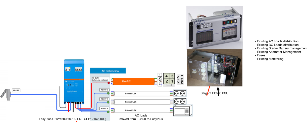
2) The output of the Victon MPPT should be fed into the EC500 so that it can be monitored by the EC480
3) A new Victron battery charger that can support up to 2 x Lithium LiFeP04 Professional 12 V 110 AH in parallel (or the vehicle battery). The output should be managed by the EC480 so that it can be switched to charge the 2 Lithium batteries or the vehicle battery as it does today)
4) A new Victron 1200W pure sinus inverter where the output is connected to the EC500 in such a way that the existing 220V sockets in the van can be used with normal appliances (in the same way as connected to the mains)

Any good suggestion is most welcome.

Thank you!

MPPT ControllersLithium BatterychargerPhoenix Inverter
2 |3000

Up to 8 attachments (including images) can be used with a maximum of 190.8 MiB each and 286.6 MiB total.

7 Answers
Trina avatar image
Trina answered ·

Well I don't know all your gear but replacing with even the most basic Smartsolar MPPT 75-15 will work. I'd get that first. If you are 12v dc it can handle the 2 PV's -possibly 4 100-120w if you are 24vdc (check the calculator app) which would get you started.

Also the Smart BLUE IP67 AC charger goes up to 25a -and- you can chain them for more amps into your LifePo4's (the limiting factor being your mains input to the BLUE IP67 and how much amps your lifepo4 set can handle max -probably at least 100a). Do that 2nd. You can ad more BLUE ip67's if needed to get faster charging to your lifepo4's -again the limiting factor being the amps they can handle and their BMS's.

You can also add more MPPT 75-15 if you get more solar (I have a spare for adding portables into my setup when I'm parked) which is a cheaper solution if you could have more solar but do not have more panels YET (vs a 150/30 MPPT which allows a lot more PV's down the road and not yet needed as the 75-15 will be fine) and the 75-15 and 100-15 are quite small (vs the 150-30 and up sizes) which is nicer in my opinion for tiny spaces and possible upgrades down the road!

I would aim for the "smart" (Bluetooth) versions and consider the BMV712 as well when you can. It's no more difficult to set up than any other monitor and comes with the shumt and all the cables needed (ad last if money is tight as you can go without by using the Bluetooth monitoring on the phones and tablets really)!

I started with the 75-15 smartsolar MPPT and the BMV712 and added the BLUE ip67 25a and then 2x more of each and another 100/20 smartsolar MPPT for my various systems.I don't have their inverter but hear it's also Bluetooth and quite a lot of features (i have samlex inverters). The Smartsolar MPPT's in the smaller sizes also have a irect-oit

Everything works together (shunt included for the BMV712 by the way) and can network and "talk" to each other and iphones and android phones/tablets and many laptops which is really nice for setting everything up to the same charging parameters and minitoring the system.

Make sure you get the 220vac versions if that is what you need for the AC side.

Super easy. I' so glad I did the upgrades.

1 comment
2 |3000

Up to 8 attachments (including images) can be used with a maximum of 190.8 MiB each and 286.6 MiB total.

amidships avatar image amidships commented ·

Hello Trina,

thanks a lot for your reply, somehow I did not get a notification and I am reading it now since I posted another question.

Your input is great and I will consider it to the alternative of going for an easy solar (that i am considering now)

Cheers

0 Likes 0 ·
Steve avatar image
Steve answered ·

Amidships, did you manage to do what your were hoping replacing sargent kit with victron? I have the same sargent setup in our Autotrail v line V600 and am looking to do exactly the same as your post set out.

1 comment
2 |3000

Up to 8 attachments (including images) can be used with a maximum of 190.8 MiB each and 286.6 MiB total.

amidships avatar image amidships commented ·

Hello Steve,

the solution is not implemented yet but I have made the design and ordered the parts.

The central concept is to put and EasyPlus C 12/1600/70-16 (PN: CEP121620000) in front of the EC500. This is an Inverter/Charger unit with built-in MCBs

https://www.victronenergy.com/inverters-chargers/easyplus-12v-1600va

So the 230 V input goes into the Easy Plus.

The EasyPlus AC Out 0 is connected to the EC500 230 V input. In this way when the van is connected to 230V the EC500 is powered transparently through the EasyPlus

Then some of the cables attached behind the EC500 that are used to feed existing 230V socket in the van are moved from the EC500 to the EasyPlus AC Out 1, AC Out 2 and AC out 3. These are also powered transparently when the EasyPlus is connected to the AC input 230V, but they also get powered by the inverter when the EasyPlus is disconnected from 230V.

In this way, I have the existing 230V sockets (of my choice) working with shore power or from the inverter.

The rest of the system depends on your battery and solar panel but the tricky part was integrating the EC500 and the above solution seems doable.

1619891040731.png


0 Likes 0 ·
1619891040731.png (283.6 KiB)
cockers avatar image
cockers answered ·

Sorry for joining the conversation so late, just wondering how the install went. I’m yet another Sargent EC 500 owner wanting to change to Victron. I have the MTTP smart charge controller BMV 712 installed and want to add a DC to DC Charger and IP22 Bartery Charger. I’m told I need to fit an Isolation relay from the D+ signal wire to the DC to DC charger. Not quite sure where to connect the Wire to on the DC to DC Charger. Does it connect to the remote on of bridge.

sorry if its a stupid question but I’m a bit new to all this tech. Or does anyone know a knowledgeable Motorhome auto electrician that can install the update in the Cambridgeshire Suffolk area.

2 |3000

Up to 8 attachments (including images) can be used with a maximum of 190.8 MiB each and 286.6 MiB total.

amidships avatar image
amidships answered ·

If you want to have a look at our modification, check out this thread:

https://www.autosleeper-ownersforum.com/t36957-warwick-xl-off-grid-modifications

Unfortunately, we have not implemented and DC to DC Orion solution (Yet?). The way the EC500 is able to charge the leisure battery seems to work.

2 comments
2 |3000

Up to 8 attachments (including images) can be used with a maximum of 190.8 MiB each and 286.6 MiB total.

David avatar image David commented ·
just to let you know, it would seem only registered users of that forum can see the thread (I know I can't), so you may want to post the actual info here to share if you feel it would be useful?
0 Likes 0 ·
amidships avatar image amidships David commented ·
I was not aware that the forum access did not allow "guest" access, anyways, I will post at the bottom of this question some info from the forum thread


1 Like 1 ·
David avatar image
David answered ·

This is an interesting thread for me as it touches on a lot of the things I have done on my own Motorhome. I won't address any specific questions but post what I did and why, which may be of interest to those who wish to have a better setup ....

For those who are not familiar with them (only UK, New Zealand and Australian folk may have come across Sargent?), Sargent is a British Company that make Power Distribution Units for Caravans (Travel Trailers) and that also get used in Motor Homes and Campervans. These provide all-in-one AC Distribution, DC Distribution, Battery Charging from Alternator and Mains, switch control for things like water pumps, outside lights, overall Habitation power, selection of DC supply, etc. So similar in many ways to many other brands such as the Schault Electroblocks and the like.

Overall they are quite a nice range of units, and some have more features than others but a fairly common thing for the great majority is their charging capabilities are mediocre and limited in capability and capacity.

The following is the additions and changes to my own Motorhome which is fitted with a Sargent EC325 PDU.

  1. Installed EasyPlus 12/1600/70. (Could have used a standard Multiplus as well). This adds much more capable Mains Charging in both current and configurability
  2. The Shore IN was changed to go to the EP rather than direct to the Sargent, and then from one of the EP Breaker outs on to the Sargent. This lets all AC sockets to work on both Grid or Inverter.
  3. Installed 60A Battery to Battery Charger. This adds much more capable Charging via Alternator (configurable Smart Charger compared to a basic relay)
  4. Installed Victron MPPT 100/20 Solar Controller. My Sargent did not have the optional solar, but if it did , it would have been a basic low -power PWM unit, so I would use the Victron unit anyway
  5. Installed BMV-712 to monitor Battery
  6. All the above are connected to the Leisure Battery as if the Sargent was not present, using sutable gauge cabling, etc.
  7. I turned off the Sargents Built-in Mains Charger (just a simple switch on the panel).
  8. I disabled the Sargents Built-in Split-Charge System so only the new B2B would operate. There are a few ways to do this. I did it by disconnecting the D+ Signal into the Sargent.

Obviously I have done other things in addition (I have a Cerbo GX, Additonal controls, etc) but the above list is essentially a way to bring a Sargent-equipped Motorhome or Campervan into the 21st Century, removing the limitiations it has, but keeping the nice (IMO) features it does have. I needed to make improvements as I wanted greater Battery capacity than the Sargent supports - I have 300Ah of Lead Carbon Battery fitted permanently, plus a Lithium Bank of between 100-200Ah depending of what I am doing.


In my Motorhome, I repurposed one of the lockers to house the Victron Kit.

victronlocker.jpg


victronlocker.jpg (595.8 KiB)
2 |3000

Up to 8 attachments (including images) can be used with a maximum of 190.8 MiB each and 286.6 MiB total.

amidships avatar image
amidships answered ·

Our van is equipped with Sargent EC500 Power System, EC480 Control Panel, PX300 Charger, 10amp Solar Regulator, 90W solar panels


These products are not suitable for our needs, so we decided for the following products as replacements/modifications:


Connections:

New battery +/- connected to the battery terminal of the DC distribution board

+ Cable connected to Terminal Fuse block on + pole

EasyPlus +/- cables connected to +/- of the DC Distribution Board (+ Fused with MRBF)

EC500 +/- battery connection connected to +/- of the DC Distribution Board (+ Fused with MRBF)

EasySolar +/- battery connection connected to +/- of the DC Distribution Board (+ Fused with MRBF)

SmartDongle glued on top of the battery and connected to EasyPlus with RJ45

Temperature Sensor connected to battery + pole and to SmartShunt on DC Distribution Board

AC IN (orange cable) Disconnected from the back of EC500 and connected to AC IN into EasyPlus

AC OUT 0 from easy plus into AC IN of EC500

AC OUT (microwave/plugs/and so on) disconnected from the back of EC500 and distributed among AC OUT 1,2,3 of EasyPlus

Ground wire from EasyPlus to DC Distribution board -

Ground wire from DC Distribution board - to chassis of the VAN

Replacement of solar panel with 2 x 10⁵W semiflexible glued on the roof

New solar panel wire from roof to the solar controller

2 |3000

Up to 8 attachments (including images) can be used with a maximum of 190.8 MiB each and 286.6 MiB total.

dougle03 avatar image
dougle03 answered ·

A note to all people looking to upgrade their Sargent based system.

The existing wiring and circuits are limited in their DC current rating. They are designed for the installation as it comes out of the factory (i.e not very high capacity), adding additional equipment such as more solar and higher capacity chargers that increases the current could well cause overload problems, particularly the existing wiring and circuit board tracks on the main board.

I've linked below a copy of the schematic that highlights the current handling limitation warnings.
I understand the desire to retain the existing current metering and SOC features of the Sargent system, but in order to do this all current must pass through the system board and this is where the problems may come.

From the schematic "Maximum solar panel power is 120W as PSU PCB is limited to 6A"
Have a look through the system schematic for further information.

Sargent EC500 Schematic


3 comments
2 |3000

Up to 8 attachments (including images) can be used with a maximum of 190.8 MiB each and 286.6 MiB total.

amidships avatar image amidships commented ·
Hi @dougle03

Thanks for the comment. Somehow your linked schematics cannot be accessed.

Regarding your concerns, those were exactly mine as well, that is why I managed to completely isolate and keep the existing EC500 wiring installation as is while adding the extra components around it. Still respecting the existing wiring from/to the EC500

Everything works perfectly and transparently

0 Likes 0 ·
dougle03 avatar image dougle03 amidships commented ·

Hi, sorry you can't get to the linked pdf. Try this link.

https://www.dropbox.com/s/ip104o3gopdsqw3/EC500%20Dealer%20Installation%20Guide%202%20Schematic.pdf?dl=0

How did you deal with the EC500 monitoring both batteries as they do by default. I know there is a shunt across the leisure battery feed, it's this element that's causing me some concern since it's counting amps out into the van but not amps back as my chargers are outside it's circuit.

0 Likes 0 ·
amidships avatar image amidships dougle03 commented ·

Thanks for the file. I can see that it's the one I already had and based my decisions upon.

Short answer is that I use a distribution bus.

I'll try to give you here an explanation of my setup without drawings, I hope I succeed.
1) I have disconnected the Sargent Solar Controller from EC500 and Solar Panel
2) I have disconnected the Sargent 3 Stage Switching Mode Battery Charger from EC500 and Battery
3) I have disconnected all 230V connections from behind the EC500 that were powering 230V wall sockets. Bolier and so fort stays connected to the EC500
4) I have disconnected the 230V input from behind the EC500
5) On top of the wooden box, housing the EC500 I have installed this DC distribution board (to save space), you can also go for a LynxDistribution. Thy both have a preinstalled Victron Shunt
https://www.outbackmarine.com.au/power-distribution/dc-distribution-boards/outback-m-series-dc-distribution-boards/
6) Negative pole of Shunt is connected to the Negative of a new LifeP04 200AH battery
7) Battery positive on Distribution connected (and fused) to Battery positive on Battery
8) I have removed the existing solar panel and replaced with 2 of 105 W making proper calculation to ensure that the max Amp will be OK with the existing wire going from the roof to the EC500
9) Victron MPPT Connected to distribution bus to charge the battery and to solar panels (with two poles switch in the middle)
10) The EC500 battery connection moved to negative/postive of the distribution bus with fuse
11) EasyPlus DC connections to negative/postive with fuse
12) Old EC500 230V IN patched into EasyPlus 230V IN
13) EasyPluls AC0 OUT (Boiler, only active on shore power) patched into EC500 230 V IN
14) Old EC500 AC OUT (for sokets, Microwave, etc) patched into EasyPlus AC OUT 1,2,3
15) Added a battery master connected on DC distribution bus and to cable that gå from EC500 to vehicle battery
16) Commected Shunt Aux to cable that gå from EC500 to vehicle battery

Result:
On shore power:
EasyPlus and MPPT keeps LifeP04 topped up
Battery master keeps vehicle battery topped up
On victron app I can see both leisure and vehicle batteries
On Sargent control panel I can both Leisure and Vehicle batteries

All 230V loads work transparently either from the EasyPlus (sockets/microwave) or through EC500 (boiler/fridge...)

On engine:
Alternator charge vehicle battery and leisure battery
Solar charges leisure battery
On victron app I can see both leisure and vehicle batteries

On solar:
Solar charges leisure battery
Battery master keeps vehicle battery topped up
On victron app I can see both leisure and vehicle batteries
EasyPlus transparently kicks in if I start a 230V load (sockets, microwave, ...)

Hope it make sense

0 Likes 0 ·