question

mvader (Victron Energy) avatar image
mvader (Victron Energy) asked

Looking for input - 4 to 20mA and 0 to 10V senders

Hello Community!

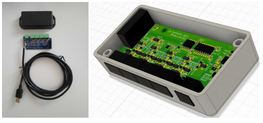
We’re considering to add a USB accessory to our GX product range, to add 0 to 10V, as well 4 to 20mA inputs.

But since all of us have very limited experience with 4 to 20mA tank senders, we're looking for some input:

  1. Is it always 4mA = tank empty, and 20mA is tank is full? Or do the empty and full levels need to be configurable in a software setting on the GX Device?
  2. And how important is it that the transducer can be powered by our device?
  3. Anything else we should keep in mind when designing a 4 to 20mA input? Good features you have seen else where?

Also, if you are using 4 to 20 mA senders, please post a link to a datasheet or specs below. And if you have an opinion on the sender, what you like/don't like, welcome to add that.

Lastly, most questions above are for 4 to 20mA, not for 0 to 10V - but if you have special comments about 0 to 10V, welcome as well - obviously. The product we have in mind will have inputs that can be used for both types.


Note, that this is quite early in the product development, I can’t say anything for now with regards to availability dates.


All the best and thank you! Matthijs


ps. just to prevent any question about this: we'll soon launch a new Venus OS version that can work with irregular tank shapes, as well as naming tanks and some more features: all those features will also available for the 0 to 10V and 4 to 20mA inputs. Details here.

Venus OSgx devicetank monitor
1 comment
2 |3000

Up to 8 attachments (including images) can be used with a maximum of 190.8 MiB each and 286.6 MiB total.

Rob Duthie avatar image Rob Duthie commented ·

Hi

Re 4-20ma senders yes that is the way to go as most industrial sensors are 4-20ma just reliable and most engineers and electricians understand and know how to use them and wire them in.

Also the 4.20ma sensor might need to software configure s in note 1. Also to be powered from the device. note 2.

You need to have sensor selection as they could be current, voltage, temp, levels, pressure,flow

Your will need a 24v DC supply is the only criteria from the CCGX as most 4-20ma require 24vdc.

Brands used high quality types IFM from Germany has a very good range of sensors.

Regards
Rob D

NZ

0 Likes 0 ·
13 Answers
mvader (Victron Energy) avatar image
mvader (Victron Energy) answered ·

Dear all, first of all many thanks for all your comments and input. Super useful & motivating.


Using that input we have come to a design and are currently awaiting the first prototypes. Here is an overview of the specifications and an image showing how its connected.


Welcome to put in comments. Have a good weekend. Matthijs


Specifications

  • A total of 4 analog input channels.
  • All channels are configurable in software to measure either 0-10V or 4-20mA.
  • Channel 1 and 2 include a built-in 24V power supply to power the sender. This power supply is an (isolated) boost converter, boosting the 5V from the USB to 24V.
  • Channel 3 and 4 do not. But there is an extra connector to facilitate easy wiring of a power supply to senders connected to those inputs.
  • All channels feature an internal 20mA self-resetting fuse
  • All channels are protected: accidentally selecting the wrong input type will not break the analog input module nor the sensor.
  • The USB is galvanically isolated from the analog side.


And the reason to power two sensors with a built-in power supply and two with an external one are cost (powering more than two sensors would significantly increase the cost), as well as offer maximum flexibility.

Note that when needed, a customer is free to not use the built-in power supply at all and power all four inputs from another source.

To minimize power draw, one *could* look into powering the senders on an interval, for example only once a minute. Which could reduce power draw significantly. But we decided against such feature. It would add complexity & more integration with the tank senders: who knows on which that will work OK, and which not.


Channel labelling:

  • Vout - Power supply to sensor
  • In - Analog input. For current sensors this is the return path, and for voltage sensors this is the analog input.
  • GND - Ground. Use for Voltage sensors only.


Configuration options:

  • Select between 0 to 10V and 4 to 20mA
  • Min & max levels are configurable (to accomodate a 0 to 5V sender, or 2 to 8V senders, for example)
  • For 4-20mA sensors, an alarm will sound when the loop is broken


Connection overview

Note that the connected sensors are just examples. One can ofcourse also use 4-20mA senders only, or only voltage outputting senders.


1591367287073.png (103.7 KiB)
6 comments
2 |3000

Up to 8 attachments (including images) can be used with a maximum of 190.8 MiB each and 286.6 MiB total.

raymiller avatar image raymiller commented ·

Great work and a great outcome, your prototype is shaping up nicely.

re power consumption: on 4-20ma sensors. You are correct the power can add up, I currently use two pressure sensors, one for water tank level and the other controlling a water pump attached to a pressure tank. In theory, your device venus etc could control the water pump power on/off without the need for other controllers.

-The water tank level only needs to be polled just before reading and then off again. Saving energy on a battery system, energy efficiency as you know is important. So this option would add value to the project though not essential.

Just a suggestion for measuring water tank levels: to give the most accurate measurement many samples need to be taken and then averaged. This method allows for small or large pressure variations which can occur when pumps send pressure pulses, which causes fluctuation in the readings, also a movement of the tank can cause pressure variations. If sufficient averaging is used the pressure sensor can even be attached to the pump inlet hose though not ideal, it does make installation much easier and cheaper. No one likes to see the likes of tank levels vary widely as this reduces confidence the system is giving a reliable reading. Just a "simple" software selection of the level of averaging depending on the application.

- having an external power supply for lower voltage is a good solution, but maybe having an onboard voltage selection?

- For the water pump pressure sensor, in this application, it needs to be on continuously.

- I like your 20ma current protection, to get information from any sensor that it is not working within expected parameters (short circuit or open circuit) is then the next level of professionalism.

- in your software, consider a maintenance display showing all the sensor current, voltages and 0-100% of full-scale reading. This is help full in fault finding monitoring sensor without the need to try to calculate back from whatever the sensor is calibrated to. This can be important if the wrong sensor is used for the application, this would show clearly a sensor fault or incorrect selection.

- any chance of adding more digital counter inputs into this product? I use flow sensors which produce pulses for each 1-litre flow. So the combination of pulses on flow meters (count) and pressure sensors with calculations of time could give; time to empty or days of supply etc and allow for volume calibration of complex tank shapes.


Look forward to seeing your production model.

Greetings from Australia

0 Likes 0 ·
mvader (Victron Energy) avatar image mvader (Victron Energy) ♦♦ raymiller commented ·

Hi @RayMiller, sorry I saw your reply several months ago - but then forgot to answer it.


Thank you for the detailed feedback. Very useful. To answer some of your questions / suggestions:

- pulse counting / digital inputs: no sorry. we can't add that. Currently, the only way to have pulse counting is to use a Venus GX (not a Cerbo GX unfortunately). The Venus GX has pulse counting capability.

- filtering: yes that will be user selectable most likely. It will take a reading every second, and you can select over how many seconds it needs to average.

- the extra option to be able to only measure for a moment, and then power down the sender, is something we end the end chose not too add. Basically the reason behind that was that we had to stop somewhere on this, to get it done and over with as well as move on to another project / product.

Here is a screenshot of the prototype & a render, quite a small unit:

Parts for the first production batch have been ordered and all other processes started as well to get to mass production. Meaning 4 to 6 months approximately, and then there will be stock.

All the best, Matthijs

0 Likes 0 ·
1599855625623.png (575.4 KiB)
Kevin Windrem avatar image Kevin Windrem mvader (Victron Energy) ♦♦ commented ·

Great work!!

Any guess as to cost?

A number of people are looking at tank sensors with voltage output with the maximum voltage in the 1 volt range. Some of these are stick-on sensors which would be great if they could interface directly to you new analog input.

As you've done with the resistance settings in 2.60, making the voltage range adjustable for these voltage inputs would be very useful. Hopefully that can be added to the software and user interface.

Will you be able to add multiple analog input units to the same GX?

0 Likes 0 ·
mvader (Victron Energy) avatar image mvader (Victron Energy) ♦♦ Kevin Windrem commented ·

Hi Kevin, thank you!


yes, min/max levels configurable.


cost, no not yet.

Multiple of these on one GX: yes


Have a good weekend!


0 Likes 0 ·
raymiller avatar image raymiller mvader (Victron Energy) ♦♦ commented ·

thanks for the reply, designing things is always a challenge especially to do it well, and the designer always needs that ring-fence otherwise nothing gets done.

Look forward to purchasing the finished product.

Cheers From Australia

0 Likes 0 ·
modian avatar image modian mvader (Victron Energy) ♦♦ commented ·

Hi Matthijs,

is there already a possibility to buy this converter box?

Cheers


Dirk

0 Likes 0 ·
Mark avatar image
Mark answered ·

0-10 V Input related

Just wondering how many input channels the analog input device your considering has and if multiple units could be connected to the GX device?

Also, is each input channel isolated from each other? (as that would be required for my proposed usage)

I have been looking for a way to monitor/log the voltage of the each individual 6v battery in my system (8 batteries in total) and a Venus OS integrated analog input device with multiple 0-10V input channels may be perfect for this.

I'm not really looking for any type of complex integration for this usage purpose, just for the voltages to be logged and available.

I recall that you were considering a USB DAQ from LucidControl some months ago, but don't know if that is still the case. https://www.lucid-control.com/product/lucidcontrol-ai4-4-channel-analog-input-usb-module/

2 |3000

Up to 8 attachments (including images) can be used with a maximum of 190.8 MiB each and 286.6 MiB total.

Daniël Boekel (Victron Energy Staff) avatar image
Daniël Boekel (Victron Energy Staff) answered ·

My fuel tank has a 4-20 mA sender...

questions:

  1. Is it always 4mA = tank empty, and 20mA is tank is full? Or do the empty and full levels need to be configurable in a software setting on the GX Device?
  2. And how important is it that the transducer can be powered by our device?
  3. Anything else we should keep in mind when designing a 4 to 20mA input? Good features you have seen else where?

answers (imho):

  1. need to be configurable (sync empty and full?).
  2. very: having to add an external power source makes things extra complicated.
  3. wire break / short circuit alarm is pretty standard

for odd-shaped (or even for every shape) tanks: ideal is some sort of 'teach in' mode: start empty, calibrate 0 - fill x liter, calibrate - fill x liter, calibrate, etc.

a configurable alarm is probably already implemented? (empty / full) (sorry haven't looked at that yet)

2 |3000

Up to 8 attachments (including images) can be used with a maximum of 190.8 MiB each and 286.6 MiB total.

raymiller avatar image
raymiller answered ·

Re 4-20ma senders or transmitters;

For pressure transmitters, they usually have high accuracy (and reliability) of the order of +/- 0.5% and have an extremely wide range of industrial applications. For pressure transmitters, the 4ma lowest pressure may not always equate to empty, for it depends where the sensor is mounted, as it could be below the storage tank in a lower pipe. The same goes for the 20ma full scale, as the transducers are of fixed pressures, the transducers will need to be selected for greater than the full hight of liquid. Software or hardware adjustments will always be needed to adjust the top 100% and bottom 0% pressures and equivalent fluid volume.

A couple of practical points; The supply voltage is commonly 24V but can be as low as 10V depending on the sensor specifications. Supply as low a voltage as you can; reduces the self-heating of the sensor and lowers the corrosion risk in hostile, moist environments. Use ideally a current limited power source i.e. to 20ma as if a short in the senor or cable does not burn out the precision 100 ohm sense resistor.

Sensors are usually two-wire (third may be a cable screen earth to reduce interference) and have a source voltage +10-24V and the return going to a precision sense resistor to ground. Precision sense resistors of 125ohms are frequently used as this gives a voltage of 2.5V = 20ma, 0.5V=4ma and a 2 Volt range.

A typical 4-20ma pressure transducer.

https://www.wika.com.au/a_10_en_co.WIKA

I did find at least one reference to a circuit.

https://www.fierceelectronics.com/components/implementing-a-4-ma-to-20-ma-sensor-interface


2 |3000

Up to 8 attachments (including images) can be used with a maximum of 190.8 MiB each and 286.6 MiB total.

Rob Howdle avatar image
Rob Howdle answered ·

Yay! Definitely interested in a 4-20mA interface. Our background is industrial automation/process control, in particular oil & gas and petrochemical. These industries are basically built on 4-20mA loops. Obviously with a 4-20mA you have built in open circuit detection (anything <4mA you can use to trigger an alarm/error state (not so easy with 0-10V as 0V could be process 0% or open circuit). What resolution are you proposing to use (10-bit, 12-bit etc)?

Very interested!


Rob.

2 |3000

Up to 8 attachments (including images) can be used with a maximum of 190.8 MiB each and 286.6 MiB total.

ripper avatar image
ripper answered ·

Almost all Diesel engines (so when talking auto start generators) should be stopped before the tank is empty to not suck air and need work for a successful next start.

Some designs of diesel engine high pressure pumps pressurize unused fuel unusually high. Their fuel in the tank gets very hot and they require a quite high "low level" for enough fuel to go around as hot fuel does not lubricate as well. They need like 50 litres left when they should be shut off.

Hence it makes sense to me to make it configurable to first have a generator shut off by tank level and this level be adjustable all the range. People use them in conjuction with heating, here an antifreeze level or temperature reading might be more interesting. Therefor being able to adjust the old under, from, between and over reading to do whatever with digital outputs would certainly be a great addition and also starting rules.

The auto start should also be forbidden to start under the same level so not to start stop cycle. Some engines will start in any case give it ten seconds to read the sensors and then decide something is wrong and stop again.

My refernce PV panel sensor is giving out 0-10V. If it wouldnt need to read liters instead of watts that would be nice. The more metrics available the more possibility to play around with.

Cheers


1 comment
2 |3000

Up to 8 attachments (including images) can be used with a maximum of 190.8 MiB each and 286.6 MiB total.

mvader (Victron Energy) avatar image mvader (Victron Energy) ♦♦ commented ·

Hi @ripper, thanks. Stopping the generator on low fuel is a nice idea - but a different project ;o), it would be an extension to our generator start/stop system. I'll keep it in mind.

PV Panel sensor: understood, thanks for the suggestion. Note that I can't make any promises there.

0 Likes 0 ·
svtti123 avatar image
svtti123 answered ·

Use the formula Pressure (P) = 0.433 × height of water in feet (h) to calculate the psi for elevated water storage tanks. The pressure at any point in the tank is given by 0.433 multiplied by the height of water above it in feet.

Convert the measurements into feet. If the measurement needs to use inches as well, convert the inches into a proportion of a foot. For example, if the tank is 2 feet and 7 inches, convert the 7 inches by using: Measurement in feet = measurement in inches ÷ 12. In the example, 7 inches ÷ 12 = 0.583 feet, 2 feet and 7 inches equals 2.583 feet.


My tank measures 1 foot so I would select a transducer that measures 0 to 1 psi or units of measurement you choose

1 foot x .433 = .084 psi or convert to other unit of measurement


then take that value and scale it to match the value you wish to display on your monitor. for example gallons or percentage. there is a wealth of information on scaling a transducer to match your analog conversion counts of your analog to digital converter on the internet just lookup scaling a tranducer .


there is a endless selection of transducers to choose from I prefer one scaled from 0 psi to max psi not using vacuum here. use the one that match's your requirements

also stick with 4ma to 20 ma because of noise immunity


1 comment
2 |3000

Up to 8 attachments (including images) can be used with a maximum of 190.8 MiB each and 286.6 MiB total.

svtti123 avatar image svtti123 commented ·

Water Pressure Depends Only on Depth, Not Container Shape

by the way .084 psi measures 30 gallon full for my tank so ,042 psi would be 1/2 tank and so on of course that values would be in ma from the transducer. that's where the scaling comes in. basically I would scale ma to match gallons of water to value in ma for a full tank of water. 0 ma empty

match transducer to psi for a little less than 20ma full tank of water

example 18 ma may represent a full tank of water keeping us below full scale on transducer but still displaying 100 percent of full value on display after scaling display.


0 ma empty

then scale ADC to match the display value you wish to use be it percent of full or gallons your choice or some other unit of measurement

for regular shaped tanks I could use gallons for irregular tanks I would use percent of full


0 Likes 0 ·
mvader (Victron Energy) avatar image
mvader (Victron Energy) answered ·

Hi all, thank you for the feedback!

hereby some answers / conclusions so far.

1) the channels will be isolated from the USB port - not from each other. For the (small percentage) of applications that needs each input isolated they'll have to install multiple of these devices.

2) resolution 8 or 12 bits - not sure yet. Probably 12 bit or more. (though more does seem overkill, I don't see how it would be necessary to go below 1% of tank level precision.

3) teach mode for the calibration: yes that would be nice, but no we're not going to make that now. Configuring odd shapes will be part of the feature set - see v2.60 for how that works. (I think there are screenshots in one of my last posts about v2.60)

4) alarms: not available yet, but coming.

5) < 4 mA open circuit alarm: yes coming.

6) top & bottom will be configurable, just like its now in v2.60 (available as beta only for now!) on the resistance tank sender inputs.

7) we're looking into powering the device. Preferably at 10 or maybe 12V. Please shout if you think it must be 24V. One reason not to make it that high is power draw from the battery, 4 full tanks at 24 Volt is a continuous 2 watts of power draw from your batteries. Half that at 12 Volt.

8 comments
2 |3000

Up to 8 attachments (including images) can be used with a maximum of 190.8 MiB each and 286.6 MiB total.

ripper avatar image ripper commented ·

Not sure I understand, I thought it plugs into the USB port and from there it goes to the sensors. The 5W to 15W available from a USB plug should be plenty? If the device needs extra power I vote for wide range input similar to Venus GX. Big camper vans and pleasure crafts go 24 to 48 Volts. Industrial is minimum 24V. Having an Orion solely to power this device I would find bothersome as one thing more to buy/ break/ install in tight places.

0 Likes 0 ·
mvader (Victron Energy) avatar image mvader (Victron Energy) ♦♦ ripper commented ·

Hi, the whole device will be powered from usb (at least thats the idea at the moment).

And it will be a boost converter, to increase voltage from usb to the required voltage for the transducers - either 12 or 24V.

Note that the usb ports on our GX Devices are not 5 to 15W; they are lower powered. 2.5W, I thought. And ccgx less. I’d need to check.

0 Likes 0 ·
ripper avatar image ripper mvader (Victron Energy) ♦♦ commented ·

Hi, alright, then I have no opinion on the matter. Cheers.

0 Likes 0 ·
Rob Duthie avatar image Rob Duthie commented ·

Hi Mvader


Should be 24v as the industrial standard world wide.

Regards

Rob D

NZ

0 Likes 0 ·
laurenceh avatar image laurenceh commented ·

Matthijs

I know I’m coming to this a bit late but on the voltage input question I have built something that works for me.

MCS in the UK have tank sensors with voltage output which is either 4.5->7.5v or 4.5->8.5v I have built adaptors like this. They need no external power and work off the voltage supplied by the sender to control the resistance presented to a GX tank input.

They fit in tube like this for potting.


They are basically a voltage divider with a virtual earth, provided by a Vref device, at around 3v. They draw about 1ma from the sender. The voltage is then used to drive a Mossfet in its linear region to present 240-30 ohm input to a standard GX tank input.
the release of Venus OS 2.6 made this possible as slight variations in the actual resistance can be configured in the UI. Liniarity appears to be very good.

It’s a nice easy solution to productise for a voltage input if you find there is a standard sender product range out there that produces voltage output ( However the idea probably won’t work if the sender output goes below around 2.5v)

Regards Laurence

0 Likes 0 ·
clinton4086 avatar image clinton4086 laurenceh commented ·

Hi Laurence, I know this is some time ago now, but I have recently got myself a Cerbo GX and was trying to find a way to connect our MCS water and fuel tank sensors when I came across this post. I have tried to revers engineer your design from the photos but unable to work it out. Is there any way you could post a circuit diagram?

1 Like 1 ·
mvader (Victron Energy) avatar image mvader (Victron Energy) ♦♦ laurenceh commented ·

Thank you Laurence, thats a clever solution. The coming GX Tank 140 accessory would be the commercial alternative to your adapter, taking up to four voltage inputs, 0-10 but also 4.5 - 7.5 and others between 0-10.


best, Matthijs

0 Likes 0 ·
pwfarnell avatar image pwfarnell laurenceh commented ·

Any chance of adding a circuit diagram for this.

0 Likes 0 ·
Bob (Victron Energy Staff) avatar image
Bob (Victron Energy Staff) answered ·

Sounds perfect! Every now and then I also get questions for ultrasonic sensors that have 0...5V... but if 0..10V will work it would be software to have 0..5V work also. https://www.svb.de/de/bepmarine-universal-tankgeber-ts1.html (the specs of this one give 0..180Ohm as well, but this is not a reall impandance so reading it on our GX devices doesn't work at this time)

2 |3000

Up to 8 attachments (including images) can be used with a maximum of 190.8 MiB each and 286.6 MiB total.

modian avatar image
modian answered ·

Hi Matthijs,

is there already a possibility to buy this converter box?

Cheers


Dirk

2 |3000

Up to 8 attachments (including images) can be used with a maximum of 190.8 MiB each and 286.6 MiB total.

danielw avatar image
danielw answered ·

Hi Victron team,

how's the development doing? Any ideas about marketing dates?

Thanks

Daniel

4 comments
2 |3000

Up to 8 attachments (including images) can be used with a maximum of 190.8 MiB each and 286.6 MiB total.

mvader (Victron Energy) avatar image mvader (Victron Energy) ♦♦ commented ·

Hi Daniel and others - production is running an some in transit even. A few more weeks, maybe a month, only.

0 Likes 0 ·
colins avatar image colins mvader (Victron Energy) ♦♦ commented ·

Hi Matthijs, Great news! Is there a part number for it? We have customers queueing up for this and would like to get orders on asap!

Thanks,

Colin

0 Likes 0 ·
mvader (Victron Energy) avatar image mvader (Victron Energy) ♦♦ colins commented ·

Hi yes, but I don’t know it right now; sorry. It will show up on E-Order soon

0 Likes 0 ·
colins avatar image colins mvader (Victron Energy) ♦♦ commented ·

Thanks Matthijs, will keep a look-out for it!

0 Likes 0 ·
tilo avatar image
tilo answered ·

Hi,

Unfortunately I just saw this thread now... so here my suggestion for the next hardware update:

Add a 4-20mA (0-10V?) OUTPUT as well.

As specific purpose in mind: to allow for more precise surplus PV energy usage, with water heaters, pumps etc. through a variable frequency drive who have 4-20mA inputs.

And as a universal purpose device for small automation projects with remote control.


2 comments
2 |3000

Up to 8 attachments (including images) can be used with a maximum of 190.8 MiB each and 286.6 MiB total.

mvader (Victron Energy) avatar image mvader (Victron Energy) ♦♦ commented ·

Good evening/morning Tilo, yes I understand the idea. That would be a separate development/another product. The issue there is that the challenge will be software, to properly control that excess solar power usage.


noted!

0 Likes 0 ·
danielw avatar image danielw mvader (Victron Energy) ♦♦ commented ·

Good morning,

that would be really great.
Usually, the PV-inverter does that by itself, together with the grid meter. Ohm-pilot etc...
I was trying to find a way to get a suitable signal from the Victron devices (Venus, Multiplus2, with EM24 as grid and ET340 as solar meter), but couldn't find one. 0-10V or 4-20mA.

Most home systems need that, because it doesn't make sense to feed-in in Germany (cost for smart meter is higher than the revenue), so instead of ramping down the PV-inverter, it would be great to regulate water heaters along the rate of solar surplus.

Is there another way to do? By using the signal from the EM24 directly, in parallel to the VenusGX? (I have the ethernet version).

Thanks

Daniel


0 Likes 0 ·
leverg avatar image
leverg answered ·

Hi @mvader (Victron Energy)

Is the sensor box already in development and for sale ?

Greetings Leverg


2 |3000

Up to 8 attachments (including images) can be used with a maximum of 190.8 MiB each and 286.6 MiB total.

Related Resources

Victron Venus OS Open Source intro page

Venus OS GitHub (please do not post to this)

Additional resources still need to be added for this topic

GX Tank 140 product page

Connecting tank monitoring to Cerbo GX