question

Ben Pearson avatar image
Ben Pearson asked

Van Installation Diagram Questions

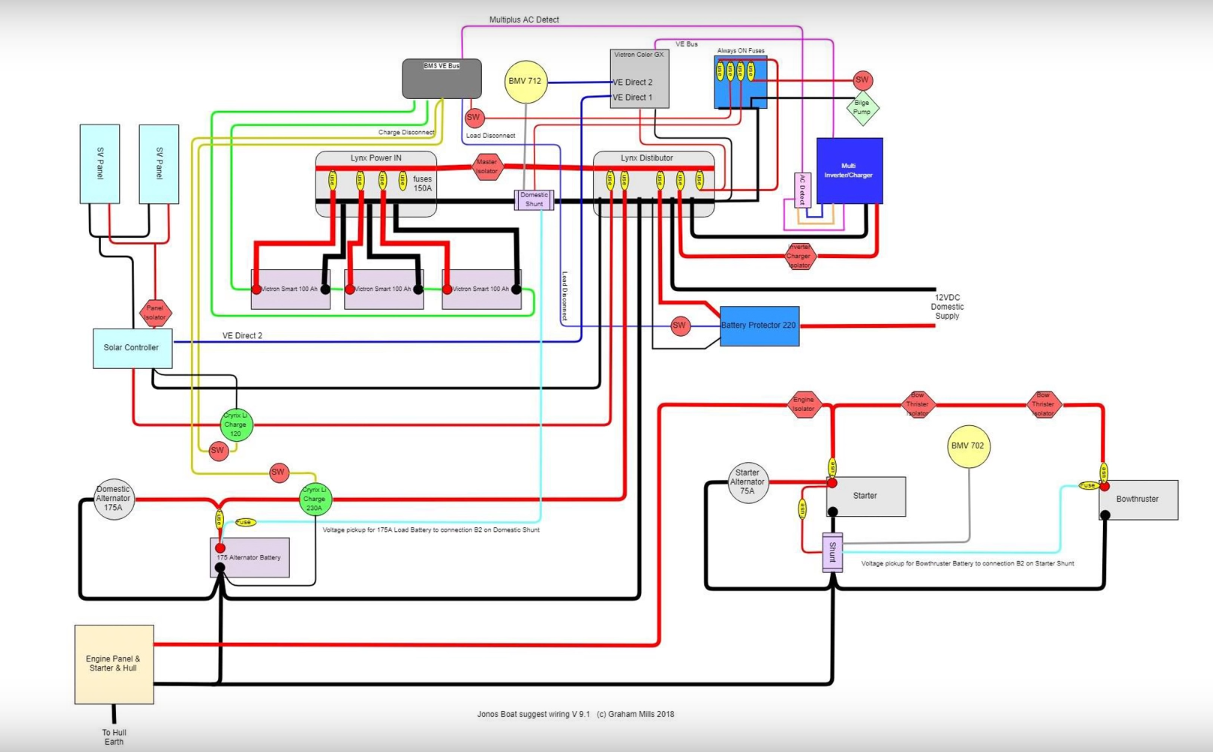
I was wondering if I could post the wiring diagram I have made in preparation for an installation in a 2018 Mercedes Sprinter Motorhome conversion with nearly all Victron equipment. I wanted to check before ordering everything that I hadn't gone overboard nor missed anything out and would really appreciate passing it by someone/s here if anybdy had any time/interest?

Thanks, Ben

MPPT ControllersLithium Batteryvictron productsschematics
2 |3000

Up to 8 attachments (including images) can be used with a maximum of 190.8 MiB each and 286.6 MiB total.

3 Answers
christyler avatar image
christyler answered ·

Post it Ben.

There's plenty of well informed people here to advise you.

2 |3000

Up to 8 attachments (including images) can be used with a maximum of 190.8 MiB each and 286.6 MiB total.

Ben Pearson avatar image
Ben Pearson answered ·

Thank you, please find attached my evolving wiring diagram for a system I am installing in a a Mercedes Sprinter 316 2018.

I just wanted to run it by people here and have a couple of points that I wanted to raise as questions as well.

I have omitted a Cyrix-Li-ct, following on from the Careful - Alternator Charging Lithium video where the buckboost would be the all encompassing solution if I am correct?

At the same time I have put a battery protect in between distribution and the buckboost in order to offer further protection to the battery, is this unnecessary?

And finally just if I have missed anything that comes to mind when looking over the drawing, I would be very appreciative of any feedback.

I hope it makes sense and is clear, if there are any explanations needed I would be quick to answer.

Thank you in advance and thanks again to this forum, I find the support and advice invaluable for my learning and when putting in these systems and is one of the reasons I suggest Victron to anyone that asks me.

Thanks

Ben


sprinter-diagram.jpg (137.2 KiB)
2 comments
2 |3000

Up to 8 attachments (including images) can be used with a maximum of 190.8 MiB each and 286.6 MiB total.

Justin Cook avatar image Justin Cook ♦♦ commented ·

@Ben Pearson, the attachment seems to have failed to attach... give it another try?

0 Likes 0 ·
Ben Pearson avatar image Ben Pearson Justin Cook ♦♦ commented ·

Thanks for the heads up Justin

0 Likes 0 ·
Justin Cook avatar image
Justin Cook answered ·

@Ben Pearson, I'll give this a more thorough looking-over as I get time, but the one thing that immediately jumps out at me is the drawn location of the BMV shunt; if you put it there, you won't be getting accurate readings. The shunt needs to be first in line on the NEG line before everything else... literally everything else. It should go batt NEG>shunt>everything else. So, in this drawing, the shunt will be on the battery side before the NEG side of the Lynx (I'm assuming you're using just one Lynx, but drew two to detail the NEG vs POS connections?).

The shunt needs to measure all current in and out of the batteries, thus why literally the only thing connected to the batt NEG should be the "battery" side of the shunt, and every other system NEG goes on the "loads and chargers" side of the shunt.

1 comment
2 |3000

Up to 8 attachments (including images) can be used with a maximum of 190.8 MiB each and 286.6 MiB total.

Ben Pearson avatar image Ben Pearson commented ·

Hey Justin,

Thank you for looking at it and for your reply.

I don't know if the diagram is clear enough but that Lynx power in (with added megafuses) would only hold POS & NEG from the 2x100AH Lifepo4s. The next door Lynx power in (with added megafuses) would then receive and distribute from/to the DC distro, MPPT, Multiplus & Buckboost. They are separated by way of isolator on the POS between them, and the shunt sits on the neg between them ensuring that it is indeed on the neg line after the batteries and before anything else, does that make sense from the drawing as it is my intention to do exactly as you say...

To explain a bit clearer perhaps, I add screenshots from Jono's video from which I have taken inspiration...

Thanks again for checking it all out,

Ben

0 Likes 0 ·
jono-distro.png (1.1 MiB)
jono-diagram.png (468.9 KiB)

Related Resources

Additional resources still need to be added for this topic

Additional resources still need to be added for this topic

Battery Compatibility

Did You Know - How to create a battery profile for non-Victron batteries?

MPPT Product Page

MPPT Error codes

MPPT 150/60 up to 250/70 Manual