question

danielk avatar image
danielk asked

Danger Reverse Current when using Battery Protect for charging

Hi together,

I have a question concerning using a BatteryProtect (BP) to disconnect the charge source in a Lithium Battery System with VE.bus bms.

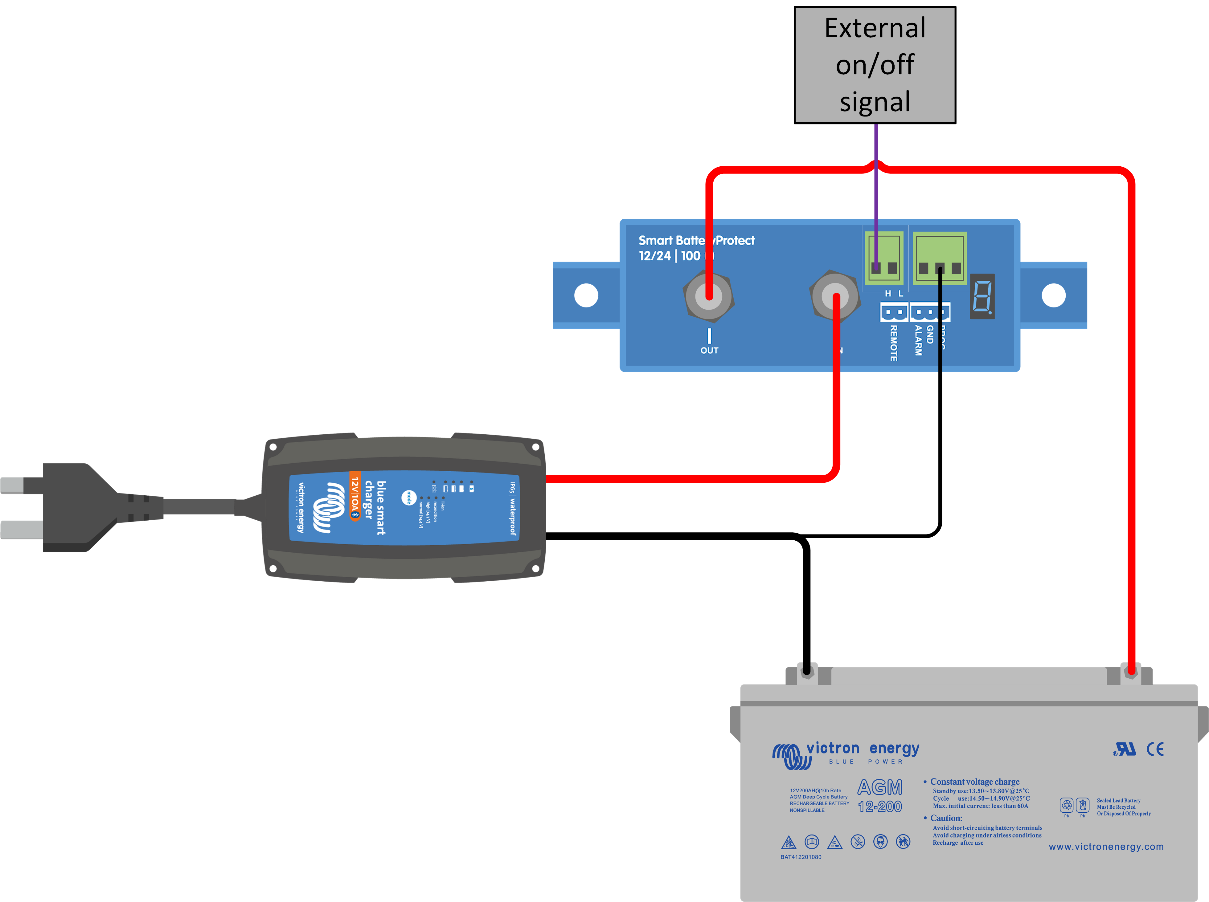
In the BP manual Figure 5 illustrates how to connect the BP for charging situation and it states that "uncontrolled reverse current will flow through a Battery Protect if Vout > Vin."

Now I wonder what happens, when the Voltage of the charger (Vin) drops, i.e. Solar charger when there is no sun or any other charging source that is swithched of. Wouldn't then the Voltage of the Battery (Vout) be higher and thus reverse current flow causing danger?

THanks a lot for your comments, I am abit affraid of burning down my RV...

cheers, Daniel

Lithium BatteryBMSchargerBattery Protect
2 |3000

Up to 8 attachments (including images) can be used with a maximum of 190.8 MiB each and 286.6 MiB total.

6 Answers
Guy Stewart (Victron Community Manager) avatar image
Guy Stewart (Victron Community Manager) answered ·

Hi @DanielK,

You are correct that the BP is designed to allow current to flow from IN to OUT terminals only.

Normally, reverse currents from OUT to IN terminals are strictly forbidden, and will damage the device.

However it is permitted to use the BP as a disconnection device for our MPPTs that do not have a load terminal. You must orient the unit in the system so that the current is flowing in the intended direction, IN to OUT.

There is virtually no current demanded by the MPPT alone when there is no PV available and it is in standby. Only mA, so this heat is easily dissipated by the BP without a risk of fire.

alt text


3 comments
2 |3000

Up to 8 attachments (including images) can be used with a maximum of 190.8 MiB each and 286.6 MiB total.

danielk avatar image danielk commented ·

Hi Guy,

thanks a lot for your answer! Now I feel much better and know that the BP is installed the correct way.

However, there is one more thing I don't understand. If I use the battery main + switch to switch of the complete system and then switch it on again, the BP gives error E1 (short circuit detected).

I then need to disconnect the VE.Bus BMS from BP's pin 2-1 and reconnect it, to make it work again.

Do you have an idea why this could be?

Thanks alot, I really appreciate Victron's support.

best,

daniel
0 Likes 0 ·
rpetrovski-forum avatar image rpetrovski-forum danielk commented ·

When BP relay is open, the voltage difference between MPPT and battery can become quite large. In particular, if remote voltage sensing is used (with smart networking over bluetooth or over Cerbo GX and such), MPPT ignores its own voltage measurements and can raise the battery voltage to above 16V on 12V system. When BP attempts to close the relay, the inrush current creates an impression of short circuit and causes the relay to open. I believe this is design fault on Victron side. It can easily be fixed with MPPT software update to ignore remote voltage sense when charge current is 0.

0 Likes 0 ·
Justin Cook avatar image Justin Cook ♦♦ rpetrovski-forum commented ·

A properly connected and configured MPPT will never output 16v to a 12v bank. Perhaps you were thinking of a PWM controller?

Example: an MPPT configured to output 14.4v (common for a 12v nominal bank) will not output over 14.4v (give or take a few mV) regardless of whether a battery is connected to it or not, unless of course it has been programmed to do so.

0 Likes 0 ·
fantail avatar image
fantail answered ·

the E1 error is caused by the inrush currents on the loads ( multi ,solar chargers , colour GX etc.

I added a current limiting circuit for powering on systems. ( bypass current to allow the system to power up slowly before the 3 automatic reset attempts are completed. with a drop out relay - so BP can still be used to disconnect the battery

2 |3000

Up to 8 attachments (including images) can be used with a maximum of 190.8 MiB each and 286.6 MiB total.

fantail avatar image
fantail answered ·

As far as reverse currents are concerned these happen all the time otherwise you would not be able to both charge and discharge your batteries.

On the other hand reverse voltages are bad.

1 comment
2 |3000

Up to 8 attachments (including images) can be used with a maximum of 190.8 MiB each and 286.6 MiB total.

Justin Cook avatar image Justin Cook ♦♦ commented ·

@Fantail, this is why using a BatteryProtect inline with an inverter/charger is expressly forbidden, because the BatteryProtect is a unidirectional device and reverse current (that is, current flowing from the "out" to the "in") will instantly and irreparably damage it.

See dot point 3 of the battery protect manual.

0 Likes 0 ·
fantail avatar image
fantail answered ·

have just compared the BP 48/100 manual I received with the one linked above. There is also nothing about reverse currents being an issue in the manual I was supplied with!! I also specifically tested to make sure that I could charge the batteries back through the BP disconnect and that only the discharge current to the load was being stopped. At the time of purchase as this was the behavior that I required.

dot point 3 is completely different in the manual that was supplied to me.

there is no date on my version so it most likely is the first released version -- but the linked one shows rev13.


I have been using it since it was released to act as a battery disconnect while allowing charging - and it has worked fine so far. ( on multiple systems)


I am aware that the BP48/100 is unable to limit or disconnect any charge current - if this is an issue the design should have included bypass diodes to allow the charge current to bypass the MOSFETs. or another set of MOSFETs for a charge disconnect and charge maximum current disconnect options. (same circuit reversed in parallel)

The charge current is controlled else-were on my systems and kept well below the 100A limit of the BP 40/100A ( anything close to or over this limit would definitely be a fire risk)


It would be nice to know exactly why victron have suddenly decided to say that reverse current is now not good from a design point of view. Just in case I have missed or overlooked something.

It also now means I have to now redesign these systems, as the BP48/100 may no longer be usable in these systems.

1 comment
2 |3000

Up to 8 attachments (including images) can be used with a maximum of 190.8 MiB each and 286.6 MiB total.

Hi @Fantail,

It was always forbidden by design, the product (old and new models) were never built for bi-directional current.

There is no change from Victron's perspective, but there HAS been a change in demand for battery protect, who is buying them, their level of Victron training, and how they are using them.

The manual was updated recently, and the original design intent is now explicit. It has also been mentioned for a long time (years) on the product the data sheet.

You will need to change the design and layout of your system so that no reverse currents are occurring to make it safe.

Very low currents are safer than large currents, and systems can seem to operate without issues when installed. All Battery Protect models should be corrected in line with the current advise in the manual.

The screen printing on the units themselves has also been updated to make this clearer (changed from Battery and Load, to In and Out).

0 Likes 0 ·
fantail avatar image
fantail answered ·

Looks like I'll have to design and build my own charge/discharge disconnect -- as the changes to manual now make it clear that the unit is unusable/ unsupported when used with hybrid inverter/charger systems. Despite the fact that in some victron approved situations reverse current is approved. The design should have had blocking diodes included to stop this confusion and prevent reverse currents. ( This would have also stopped it working with the victron MPPT charges as described above) These units as designed are at risk of failure in any system with significant capacitance.

2 comments
2 |3000

Up to 8 attachments (including images) can be used with a maximum of 190.8 MiB each and 286.6 MiB total.

Justin Cook avatar image Justin Cook ♦♦ commented ·

"...in some Victron approved situations reverse current is approved." This is incorrect. There are zero situations in which reverse current has ever been approved; the only change made to the manual is to make it clearer to the end-user that this is forbidden.

These units, when installed as designed, serve a very important purpose in a DC distribution system; the problem has only arisen when people started installing them in configurations other than as expressly approved. Incorrect assumptions of how a sensitive electronic device can be connected do not reflect a design flaw in the device itself, but only in the reasoning of the installer.

0 Likes 0 ·

I haven't heard of any issues yet when they are installed as described in the (updated) manual.

What do you mean by the "victron approved reverse current situations"?

If you mean the self-consumption of our MPPTs during night time, that is only milliamps, and well within the heat dissipation capacity of the battery protect, so no danger.

There is a good video tutorial of how battery protects can be safely used for charge and discharge in the Victron VW Van Electronics series.

0 Likes 0 ·
kiko avatar image
kiko answered ·

Hi, I have a system design very close to the Victron van install. Just instead of using a Buck Boost, I'm using an insulated Orion-Tr Smart. I connected the "Remote H" of the BP to the "Charge disconnect" of the VE.Bus BMS. Additionally, I also connected the "Remote H" of the Orion-Tr to the "Charge disconnect" of the VE.Bus BMS, to stop it from charging, if the BMS tells it to. I know, that this is a double protection.

Is this a correct way of using a BP on the charge side without the danger of a reverse current?

Tanks, Kilian

2 comments
2 |3000

Up to 8 attachments (including images) can be used with a maximum of 190.8 MiB each and 286.6 MiB total.

Matthias Lange - DE avatar image Matthias Lange - DE ♦ commented ·

The important thing is that you connect the output of the Orion to the input of the BP and the output of the BP to the battery.

0 Likes 0 ·
kiko avatar image kiko Matthias Lange - DE ♦ commented ·

OK, thank's, that was clear... The connectors on the BP 220 are called "Battery" and "Load". So in this case, the Orion is connected to "Battery" and the Battery to "Load", as usually current flows from the batteries to the load, right?

0 Likes 0 ·

Related Resources