question

Matias Käkelä avatar image
Matias Käkelä asked

Inconsistency between Victron manual and real life when using VE Bus BMS V2

Hello Victron Community,

I have an issue with my setup involving an EasySolar 24/1600, Cerbo GX, and BMS V2. Despite following the VE.Bus BMS installation manual from the Victron website, I couldn't get the remote on/off charge switch to work. The settings always indicated that the BMS was in control, preventing any mode changes using the GUI.
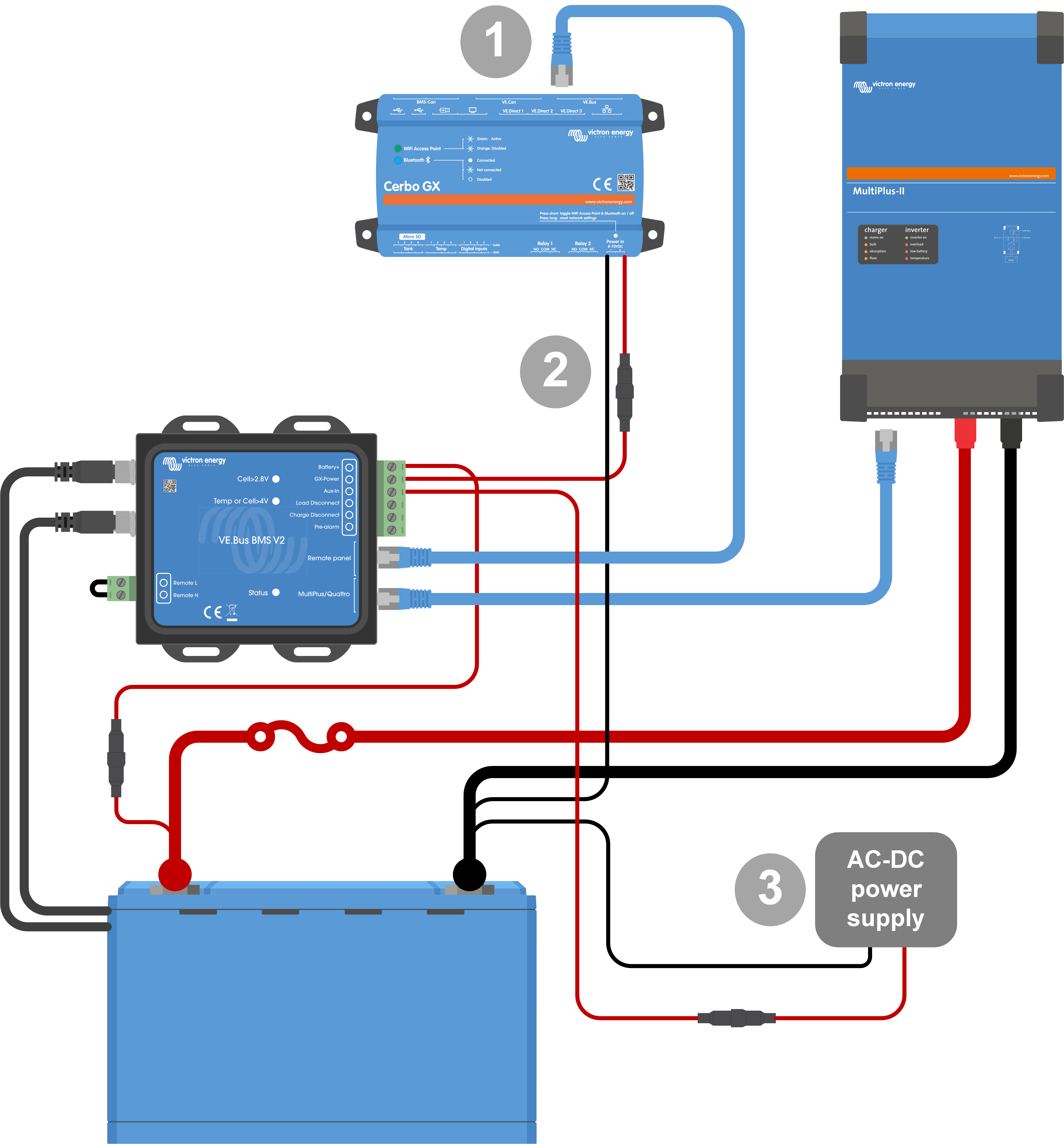
Here is my setup:

1. BMS is connected to the battery data ports

2. BMS is connected to Cerbo GX using the remote panel connector.

3. BMS is connected to EasySolar using the Multi/Quattro connector.

4. Cerbo GX is directly connected to EasySolar.

5. BMV 712 is also connected to Cerbo GX.

6. BMS is connected to the battery plus for power.

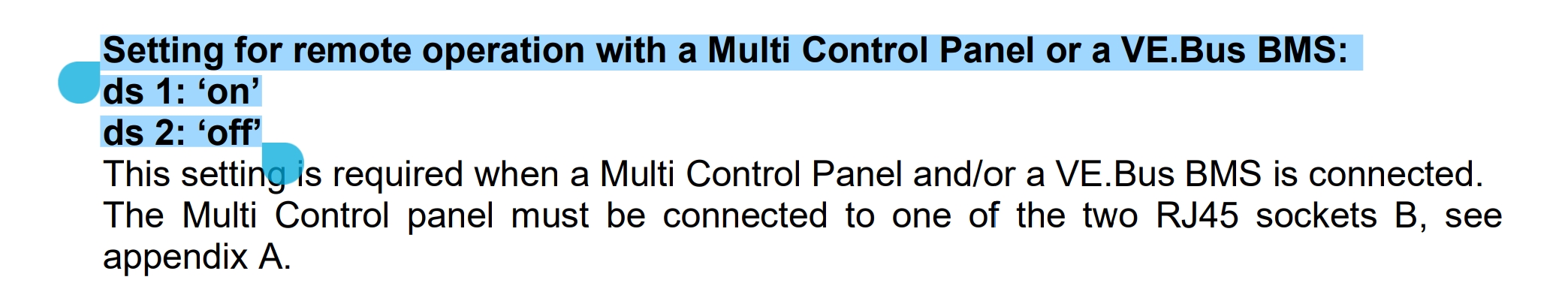
I've tried various solutions, including changing dip switches in EasySolar, using different cables, switching the VE.Bus cables to different slots, and adjusting settings, but nothing worked.

Frustration led me to try a different approaches. When I disconnected EasySolar from the BMS, leaving the BMS only connected to Cerbo GX, the remote functionality suddenly worked. Despite the cable being disconnected all BMS related functions seemed to continue working. For instance solar charger was still “Controlled by BMS”

This is confusing because all Victron manuals with Cerbo and inverter/charger setups show connections to both devices.

I'm reaching out for two reasons:

1. Have I misunderstood something regarding the wiring, or what could explain this counterintuitive behavior?

2. There seem to be many message threads with similar issues related to BMS V2 and mode changes. Perhaps my experience can help others too.

Thank you for your assistance and insights.

cerbo gxBMSEasySolar All-in-One
1 comment
2 |3000

Up to 8 attachments (including images) can be used with a maximum of 190.8 MiB each and 286.6 MiB total.

Hello @Matias Käkelä,

If there is an error in one of our manuals, we would like to correct it.

You said "This is confusing because all Victron manuals with Cerbo and inverter/charger setups show connections to both devices."

Which manuals are you talking about exactly?

0 Likes 0 ·
2 Answers
Matthias Lange - DE avatar image
Matthias Lange - DE answered ·

Remove connection 4 (Cerbo to Easy solar).

1000036182.png


1000036182.png (604.0 KiB)
2 |3000

Up to 8 attachments (including images) can be used with a maximum of 190.8 MiB each and 286.6 MiB total.

Matias Käkelä avatar image
Matias Käkelä answered ·

Indeed what @Matthias Lange - DE above suggests. The manual in question is VE Bus BMS v2 manual https://www.victronenergy.com/upload/documents/VE.Bus_BMS_V2/111619-VE_Bus_BMS_V2_-_Manual-pdf-en.pdf


There is the diagram shown above where BMS is connected simultaneously to Cerbo and Multi (or in my case EasySolar). This cabling does not seem to work in real life scenarios. Instead the mentioned diagram should not have the cable between Multi and BMS.

Of course it could be that I’m missing something important here

7 comments
2 |3000

Up to 8 attachments (including images) can be used with a maximum of 190.8 MiB each and 286.6 MiB total.

@Matias Käkelä

Thank you. I just checked all the images and drawings in the manual, but I cannot see the one you refer to. Please add a screenshot of that diagram you are talking about if you don't mind.

0 Likes 0 ·
Matias Käkelä avatar image Matias Käkelä Stefanie (Victron Energy Staff) ♦♦ commented ·
0 Likes 0 ·
Stefanie (Victron Energy Staff) avatar image Stefanie (Victron Energy Staff) ♦♦ Matias Käkelä commented ·

Okay, now I get it. I misread it. Of course, the BMS needs to be connected to the Cerbo AND the BMS simultaneously, just like in the image Matthias posted. Ensure sure you don't have the EasySolar connected to the Cerbo directly.
If you had it wired that way, I wonder where it is coming from because the manual doesn't suggest having a direct VE.Bus connection between Multi/EasySolar and Cerbo.

0 Likes 0 ·
Matias Käkelä avatar image Matias Käkelä Stefanie (Victron Energy Staff) ♦♦ commented ·
Thank you. I'm currently away from the location, but I will doublecheck and ensure the connections are as described in this thread, and make an update here about the outcome.
0 Likes 0 ·
Matthias Lange - DE avatar image Matthias Lange - DE ♦ commented ·
I installed a few systems exactly like shown um the picture above and it works perfectly fine.
0 Likes 0 ·
Matias Käkelä avatar image Matias Käkelä Matthias Lange - DE ♦ commented ·
@Matthias Lange - DE So you are saying that in your installations you have not have the need to remove the cable between Multi and BMS V2? Given what the diagrams show, that's what I would have also expected, but in my practical case I'm seeing the very opposite: the cable between Multi and BMSv2 makes the remote control non-functional.
0 Likes 0 ·
Matthias Lange - DE avatar image Matthias Lange - DE ♦ Matias Käkelä commented ·

You might have to restart the whole system after changing the data wiring.

As I wrote I installed a few systems exactly like shown in the diagram without problems.

The DIP switches should be like that:

1000036194.jpg

0 Likes 0 ·
1000036194.jpg (252.6 KiB)