question

valden avatar image
valden asked

Where is the full resolution version of this diagram? It shows Arco Zeus integration.

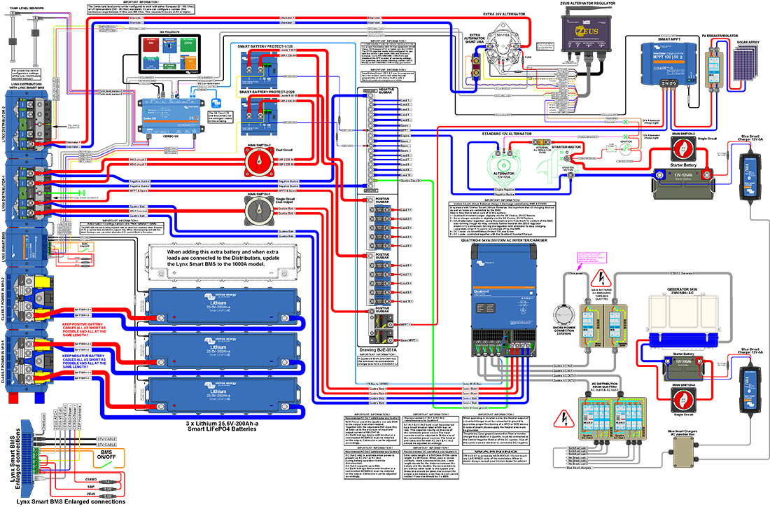
Can someone please provide a pointer to the location on Victron's site of the full resolution version of this diagram (attached)? I've hunted by various means and can't find it. It shows an Arco Zeus alternator regulator integrated into a Victron battery storage system.

I will ask a separate question about how the battery voltage sensing wires from the Arco Zeus need to be connected to the Victron system. I'm hearing that holes should be drilled into the Smart Shunt?? No thanks!

victron-system-with-zeus-regulator.jpg

cerbo gxLithium BatterySmartShuntalternator
2 |3000

Up to 8 attachments (including images) can be used with a maximum of 190.8 MiB each and 286.6 MiB total.

2 Answers
valden avatar image
valden answered ·
2 |3000

Up to 8 attachments (including images) can be used with a maximum of 190.8 MiB each and 286.6 MiB total.

JohnC avatar image
JohnC answered ·
10 comments
2 |3000

Up to 8 attachments (including images) can be used with a maximum of 190.8 MiB each and 286.6 MiB total.

valden avatar image valden commented ·

Hi John. Yep, the link is the same. :-)

So now to figure out how the Zeus' battery voltage sense wires need to be connected. My system has a Smart Shunt, a Smart BMS CL 12-100 and a Cerbo. I'm thinking that connecting the battery voltage sense wires to the positive and negative bus bars should work, but Andre Cormier (who worked on the design of the Zeus?) prefers to drill holes in the Smart Shunt! Yikes! I won't be doing that. This is where he offers this advice. Look at 12:25 in the video. It should start there.

https://youtu.be/zDbQ_ILbeA4?si=o6seHbZMBPAksEIu&t=745


0 Likes 0 ·
JohnC avatar image JohnC ♦ valden commented ·
@Valden

'Busbars' might be a bit far away. You could try with tabs on the Smartshunt terminals..

0 Likes 0 ·
valden avatar image valden JohnC ♦ commented ·

Yes, in some installations the bus bars could be some distance away, but in mine they're right next to the Smart Shunt. Cable distances are short too.

I notice in the diagram that the battery sense cables are connected to the 'bus bars', which in this setup are the Lynx Distributors. My system has simple bus bars and a Smart BMS CL 12-100. As for the Allowed To Charge (ATC) cable, I'm looking to see how it can be connected to the BMS.


0 Likes 0 ·
klim8skeptic avatar image klim8skeptic ♦ valden commented ·
@Valden in the pdf the shunt shown is bare, not a SmartShunt. Looks to be used by the zeus to monitor/control alternator current. The Victron side of the system uses the Lynx Smart BMS to monitor current.


Plenty of bare 500A-50mV shunts on ebay.

0 Likes 0 ·
valden avatar image valden klim8skeptic ♦ commented ·
Yes, the shunt drawn next to the 24V alternator is an 'alternator shunt', not a Smart Shunt. This diagram doesn't have a Smart Shunt. As you say, it's using the Lynx Smart BMS to monitor current.

I'm presently reading the manual for the Lynx Smart BMS to find clues on how either the Cerbo or Smart BMS CL 12-100 in my existing system could be used to provide an Allowed To Charge signal to the Arco Zeus. A relay control from the Cerbo could be the solution ... . I don't have a Lynx Smart BMS.

I'll also be looking at the Arco Zeus to see what it needs for a valid Allowed To Charge voltage and whether it's adjustable/programmable.


0 Likes 0 ·
klim8skeptic avatar image klim8skeptic ♦ valden commented ·

@Valden I'm presently reading the manual for the Lynx Smart BMS to find clues on how either the Cerbo or Smart BMS CL 12-100 in my existing system could be used to provide an Allowed To Charge signal to the Arco Zeus.

Look at the Smart BMS CL 12-100 manual. The BMS "Charge disconnect" is the same as the Lynx ATC (As per the pdf) and will supply a battery + signal to allow charge (or charge disconnect) for the Zeus.

Smart BMS CL 12-100 has a charge disconnect signal of 10mA only, check how much current the Zeus needs for ATC.

0 Likes 0 ·
valden avatar image valden klim8skeptic ♦ commented ·
I started with the manual for the Smart BMS CL 12-100, with exactly this thought in mind. I concluded it wouldn't provide the right voltage signal, but I'll look again. Thanks for the suggestion.


Right now I'm trying to get info on what the Arco Zeus wants for an Allowed To Charge (ATC) signal. Their data is not as freely available as Victron's. :-|
0 Likes 0 ·
valden avatar image valden klim8skeptic ♦ commented ·

I've just found this on Arco's site for the Zeus. Under 'Specifications - Connections' there is:

Dedicated Signal Wire To disable charging from an external source such as BMS


So it appears that Allowed To Charge for the Zeus is the default state, which can be interrupted by the Smart BMS CL 12-100 signalling a change to this state, via the Charge Disconnect output, which is normally high at battery voltage - 0.1V.

Or, what you said. :-)

0 Likes 0 ·
klim8skeptic avatar image klim8skeptic ♦ valden commented ·

@Valden dont forget that the BMS will disconnect the alternator charge input, in addition to activating ATC/charge disconnect.

2.1 It monitors and protects each individual battery cell within the battery (or battery bank) and will disconnect the alternator, charge sources or DC loads in case of low/high battery cell voltage, or high temperature.

0 Likes 0 ·
valden avatar image valden klim8skeptic ♦ commented ·
I started another thread this morning, asking Victron about exactly this question of disconnecting the alternator charge through the Smart BMS CL 12-100. In that thread I'm asking why it doesn't cut charging when there is a low temperature signal from a battery cell. I'm curious about that.

If I'm concerned about cold conditions I'll assess the battery temperature and might use the 'Alternator Only' option within the BMS's On/Off funtion. That's handy. :-)

0 Likes 0 ·