question

biome avatar image
biome asked

Multi mode PYLON US5000 with Inverter RS

Hi !

I have a comm issue with my Cerbo GX device and 2 groups of PYLONTECH US5000. Indeed, for some reason the BMS stops reporting the moment I connect my 2xUS5000 together in Multi-group mode.

My setup consists of 2 groups of 1xUS5000 connected together with the BAT-BAT cable (labeled WI0SCAN35RJ3) and the battery 1 connected to the GX with the Battery BMS to CAN type A, GX terminated on its 2nd BMS CAN port.

1709128101181.png

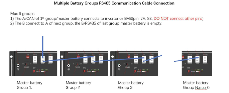
All my DIP switches are set to 0000 and when both batteries are starting the battery 1 rings 3 times meaning the whole group is online. Additionnaly each battery is connected to its respective inverter RS and both RS are daisy chained to the GX via VE.Can for a parallel installation.

Thank you in advance for any suggestions !

PylontechMulti RS
1709128101181.png (128.1 KiB)
2 comments
2 |3000

Up to 8 attachments (including images) can be used with a maximum of 190.8 MiB each and 286.6 MiB total.

Alexandra avatar image Alexandra ♦ commented ·

@biome

How many batteries do you have altogether.in the bank?


0 Likes 0 ·
biome avatar image biome Alexandra ♦ commented ·

@Alexandra

1x US5000 for each inverter RS so 2 batteries in total
0 Likes 0 ·
3 Answers
duivert avatar image
duivert answered ·

from the information in your post it looks like you have wired the batteries individualy to the RS inverters?


it should be one bank (so both batteries in parrallel)

2 |3000

Up to 8 attachments (including images) can be used with a maximum of 190.8 MiB each and 286.6 MiB total.

Alexandra avatar image
Alexandra answered ·

@biome

The inverters should share one central bank. Ideally centrally connected with a bus bar.

They are not two stacks but one bank now.

One master, one slave. Only the master connects to the Cerbo. The second with the link cable for communications to the master using RS485 ports.

2 |3000

Up to 8 attachments (including images) can be used with a maximum of 190.8 MiB each and 286.6 MiB total.

biome avatar image
biome answered ·

@duivert @Alexandra

Yes each RS has its individual battery.

I know that Victron's manuals say that the inverters have to share one central bank of battery, however after an exchange with victron they told me that it was not mandatory for a 3 phase configuration with multi RS (my final objective). The configuration I depicted above is a test I am trying to run in order to see how to manage the batteries in this future "3 phase without central bank batteries" configuration.

I am trying this unusual configuration because I have the project to be easily capable of switching between 3 individual 1 phase configuration of Multi RS with each its GX and its respective battery, into a 3 phase Multi RS configuration. This switch of configuration would be easier without creating each time a central parallel bank of batteries.

3 comments
2 |3000

Up to 8 attachments (including images) can be used with a maximum of 190.8 MiB each and 286.6 MiB total.

Alexandra avatar image Alexandra ♦ commented ·

@biome

Then each inverter is not a part of one system - you have two systems one on each phase. As individuals and you will have to use a GX for each one right now since a GX can only control one system at a time.

You can't parallel or split phase the Multi RS as of today (apparently it is in the works) see the RS manual under tech specs.

0 Likes 0 ·
Alexandra avatar image Alexandra ♦ Alexandra ♦ commented ·
0 Likes 0 ·
1000026904.jpg (64.8 KiB)
nickdb avatar image nickdb ♦♦ commented ·

"I know that Victron's manuals say that the inverters have to share one central bank of battery, however after an exchange with victron they told me that it was not mandatory for a 3 phase configuration with multi RS"

I highly doubt that was a Victron staff member, I suspect you have misunderstood.

The docs are 100% accurate. There is no ambiguity wrt to what you can do,


0 Likes 0 ·