question

stgermain45 avatar image
stgermain45 asked

Two Multiplus in Standalone

I currently have two 12/3000/120-50 Multiplus units running in parallel. Victron LiFePO4 smart batteries, VE.Bus BMS, Digital Multi Control, and VenusOS running on a Raspberry Pi with Multiplus connected via MK3-USB cable and BMV712 connected via ve.direct-USB. This is on a boat, all works great. However, I'm now in a marina in Fiji with 50Hz shorepower and the 60Hz air conditioner units sound horrible running at the slower speed. It's unbearably hot, and running the high draw aircon units off paralleled inverters for a length of time, then turning off to charge isn't cutting it. I'd like to be able to use one Multi for inverting only and the other for charging only. To do this, I installed input and output breakers on L1 and N of both Multiplus units, and my thought was to reconfigure them for standalone use, block the AC input of one Multiplus (inverter only) and block the AC output of the other Multiplus (charging batteries only).


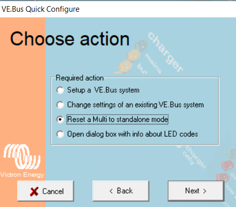
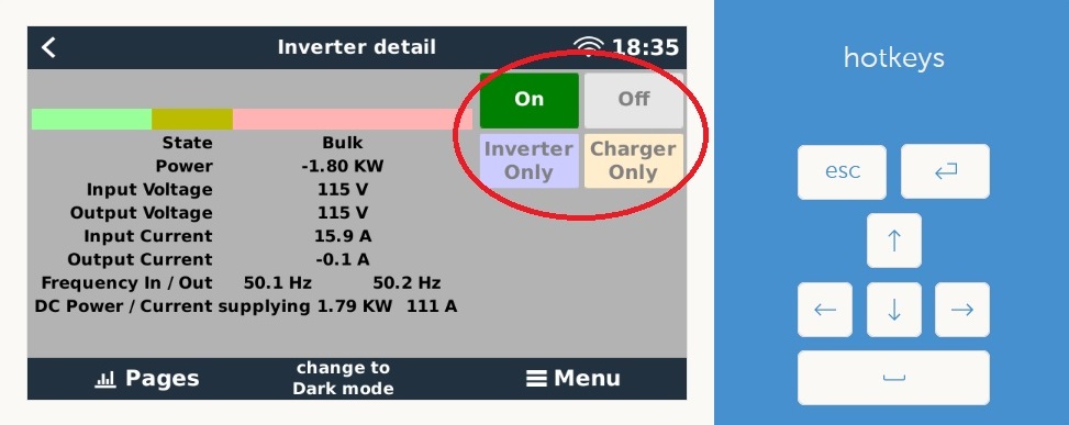
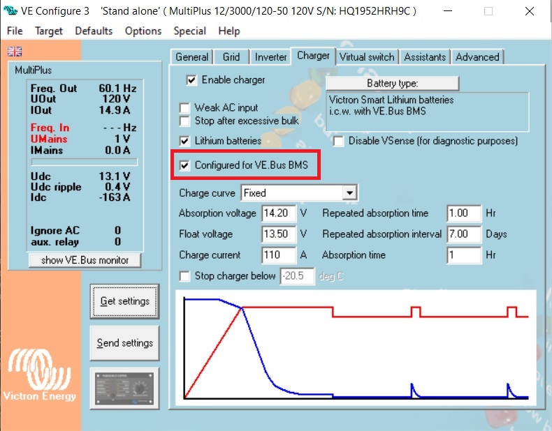
I've read that this is possible on the Victron community forums, the caveat being that one Multiplus must be connected to VE.Bus and the other connected via MK3 cable to a GX device - so monitoring of one Multi will be unavailable. After doing this, the standalone Multiplus connected with MK3 goes into "Low Battery" alarm and will not charge or invert. I can only get it into "Passthru" if shore power is available. After installing the breakers, all still works fine in parallel mode. Can someone comment whether Standalone of 2 Multis is indeed possible, and if so, please provide some guidance? Also, will BMS functionality be impacted by this setup?

VE.Busmultiplus in parallelmultiple inverters
4 comments
2 |3000

Up to 8 attachments (including images) can be used with a maximum of 190.8 MiB each and 286.6 MiB total.

klim8skeptic avatar image klim8skeptic ♦ commented ·

@stgermain45 Being a stand alone multi as a charger, and a gx controlled multi as an inverter, you would have to disconnect the charger multi from the BMS / gx. That would disable DVCC and BMS control of the charger multi.


DVCC might not be such a loss. However lack of BMS control would be dangerous for your battery. You could explore using the ATC output of the BMS to control the charger multi to protect your batteries.

The DMC would have to be relocated to the charger multi to control ac input limit.

Proceed with upmost caution.

Do make sure that the ac output(s) of the charger multi is disconnected.

0 Likes 0 ·
stgermain45 avatar image stgermain45 klim8skeptic ♦ commented ·
Don't currently use DVCC. I do have a spare 220A Smart Battery Protect lying around I no longer use. I could probably put that on the DC positive output of the charger Multi to make it BMS protected. Definitely not partial to making this a temporary wiring change if there's an alternative better way. We're at anchor most of the time, and we'll be going back to parallel Multis at that point. I'm not understanding why the DMC needs to be relocated to the charger Multi. Can't this be set in the "Shore Limit" setting in VE Configure and unticking "Overruled by remote".


Even so, I'm uncertain what I'm doing wrong in configuration that makes the Multi not connected to VE.Bus persist in low battery alarm and become unusable. When I untick the setting for it to use VE.Bus the Multi makes a loud groan for ~5 seconds. I saw it transition from red light to normal green, but then it resorted back to VE.Bus control after 30 seconds or so and back to alarm condition. This was with desselecting Victron smart lithium in the Charger settings and instead selecting the generic LiFePO4 option.

Really appreciate the help!


0 Likes 0 ·
klim8skeptic avatar image klim8skeptic ♦ stgermain45 commented ·

@stgermain45 Seeing as 230v @ 60Hz is rare, your multi is a 230v unit? Any isolation transformers, or autotransformers in your system? The ac output of the charger multi has been disconnected?


If you can do without the DMC just leave it disconnected.

You can bypass the ac detector if fitted.

Any chance the BMS assistant if still loaded and running?

The BP will work with the BMS, wire it up correctly, and remove it when the charger multi reverts to inverter/charger operation.

Generic lithium preset looks ok.

0 Likes 0 ·
stgermain45 avatar image stgermain45 klim8skeptic ♦ commented ·
120V boat and 120V multi. We have a Victron 3600W auto isolation transformer on shorepower 230V input and it's setup to output 120V. Since I now installed breakers on AC input and output of both multis (to maintain wiring lengths, etc when transitioning back to parallel), I've tried various scenarios blocking input and output. Either multi can be charge-only or invert-only depending on the breakers. But so far no luck getting it to work. No BMS assistant running anymore, as it's baked into the firmware now. Only assistant is an AC current sensor on aux input 1 and coupled on AC input 1. I'll try some more of the ideas presented thus far and report back. Thanks for your help!
0 Likes 0 ·
1 Answer
JohnC avatar image
JohnC answered ·

@stgermain45

I think you might have to separate off the 'Charger' Multi's VE.Bus from the RPi. Maybe give it the DMC to control it. So it becomes just a DC supply to the monitored part of the system.

You may already have the DC Power tile set up on the Console, and can see what it's charging (nett at least) there.

9 comments
2 |3000

Up to 8 attachments (including images) can be used with a maximum of 190.8 MiB each and 286.6 MiB total.

stgermain45 avatar image stgermain45 commented ·
Please see my previous comment. I'd still like some guidance on how to get the Multi not connected to VE.Bus to do anything. The MK3 cable was connected to my PC (not the RPi) when I tried to desselect VE.Bus in VE Configure.


If it's helpful, I also updated firmware to the latest on both units.


Thanks!


0 Likes 0 ·
JohnC avatar image JohnC ♦ stgermain45 commented ·

@stgermain45

You've done this?..

1706765626544.png

Quick Configure is part of the VE Configuration Tools download. A truly standalone Multi can run with nothing plugged into it's VE.Bus port.


0 Likes 0 ·
1706765626544.png (72.7 KiB)
stgermain45 avatar image stgermain45 JohnC ♦ commented ·
Yep, reset to standalone mode on both units using VE Quick Configure. I'm thinking my issue has something to do with the VE.Bus setting in the Charger section. But when disabling it, the unit groaned loudly and reverted back on it's own. When doing so, it was not connected to the BMS or Rpi/Venus OS so it's perplexing.
0 Likes 0 ·
JohnC avatar image JohnC ♦ stgermain45 commented ·

@stgermain45

"the VE.Bus setting in the Charger section"

Sorry, I don't know what you mean by this.

0 Likes 0 ·
stgermain45 avatar image stgermain45 JohnC ♦ commented ·

charger-ve-config.jpg

This setting. It is all working now. As I presumed, this setting was the reason it was not working. For one reason or another, the Multiplus still knew a BMS was in the picture and it would revert this setting. I don't know what exactly it was, but today I made sure the charger multi was purely standalone and the other multi off while making configuration changes. When toggling off that setting it did not make a loud groan and instead flipped over to normal green status. After a quick test making sure battery charging was working from the one multi and inverter-only from the other multi @60Hz, I then turned everything back off and installed the 220A smart battery protect on the charge-only multi. Now the charger-only multi will also be BMS connected. I tested this as well by pulling the cable to the H terminal of the BP - charging/BP output turned off.


My only outlying question: I am now using the DMC for the charger only multi. Is it possible to control the other multi inverter on/off with Venus OS/RPi screen? I updated to v3.14 and am running GuiMods v9.2. The "On" and "Off" buttons don't do anything at present. Likewise, no control from VRM with the "Inverter/Charger Control" option turned on.

0 Likes 0 ·
charger-ve-config.jpg (139.8 KiB)
JohnC avatar image JohnC ♦ stgermain45 commented ·
@stgermain45

Yes, you can use the RPi as normal with the 'Inverter' Multi. But don't set up any comms between the 2 units, they need to be truly standalone.

I confess to overlooking your bms, but you only have de-facto comms there with the Battery Protect. But be very careful not to use the 'Charger' Multi to supply any AC, you'll destroy the BP. Using a BP on a Multi is "Strictly forbidden" in normal circumstances, so take care.

0 Likes 0 ·
stgermain45 avatar image stgermain45 JohnC ♦ commented ·

Oh yes, I am very well aware that the BP current flow is one direction only. I'd prefer not to use it, but I don't see a better workaround for protection.


Any tips on how to get the RPi controls working? Attached pic. I know previously these were locked out when using a VE.Bus BMS and required a DMC, but that wouldn't seem to be the case anymore:

https://community.victronenergy.com/questions/50918/is-dmc-gx-still-required-for-systems-with-vebus-bm.html

inverter-control.jpg

0 Likes 0 ·
JohnC avatar image JohnC ♦ stgermain45 commented ·
@stgermain45

Sorry, RPi is foreign to me. Maybe take a look/search/ask that in the Modifications Space.

0 Likes 0 ·
stgermain45 avatar image stgermain45 JohnC ♦ commented ·
Ok, thanks.
0 Likes 0 ·