question

mikemynis avatar image
mikemynis asked

How to connect 2 MultiPlus 2?

Hi guys,

I have ordered (will be delivered in a week from now):

  • 2 x MultiPlus-II 48/5000/70-50 230V
  • 1 x SmartSolar MPPT RS 450/200-TR
  • 1 x Victron Cerbo GX
  • 1 x Victron GX Touch 70
  • 1 x Interface MK3 USB

My question is how to connect them together? What cables/wires do I need?
This Victron system will replace my current Growatts (2 SPF5000 in parallel mode).

I have 2 solar arrays (4 wires coming into the shack where I will install everything).
So, I assume that each solar array must be connected to its own MPPT tracker. That's easy.

Now for the battery bank: I have 5 Pylontech US3000C batteries in parallel.
I understand they need to be connected to the MPPT RS 450/200-TR. But they must also be connected to both MultiPlus.

What's the best way to do it?
I saw a video of a guy with a fried Multiplus, because the wires were stripped too short.
(https://www.youtube.com/watch?v=wEgFafmsJfk)

In the discussion below someone talks about ferrules. Another guy tells NOT to use ferrules.

So I wanna do it right. What's the best way to connect everything and which wires do I need?

Thanks,
Mike


Multiplus-IIcerbo gxMPPT SmartSolargx devicemk3-usb
2 comments
2 |3000

Up to 8 attachments (including images) can be used with a maximum of 190.8 MiB each and 286.6 MiB total.

the-doon avatar image the-doon commented ·
May I ask why you decided to go for the 2 x 5000s instead of 1 x 10000?
0 Likes 0 ·
mikemynis avatar image mikemynis the-doon commented ·

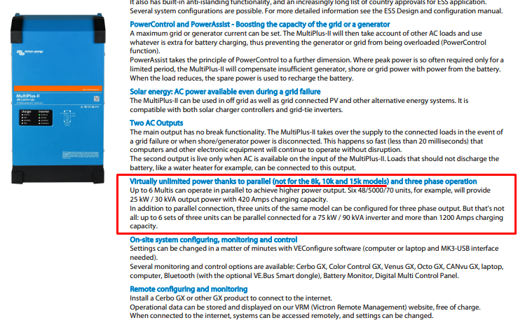
The 8k, 10k and 15k models cannot be extended (parallel). Only the 5k. So if I want to extend the system in the near future to 15k, 20k, 25k or 30k, then you can do that with the 5000s. (max 6 x 5000s = 30kVa)

See this screenshot taken from their documentation:
screenshot-1.png

0 Likes 0 ·
screenshot-1.png (196.7 KiB)
1 Answer
kevgermany avatar image
kevgermany answered ·

Questions like this should really be referred to an expert installer. But I'll do my best.

That video shows burn out, probably due to badly made connections, possibly undersized cable. Heavy loads on a 12V system result in heavy current on the system. Heat comes from current and resistance. There's a long thread here where a user used the clamps to compress the ferrules instead of crimping correctly.

Ferrules. The green rising clamp connectors do not need ferrules, they're designed to spread the cables to increase contact area and reduce resistance. Connections with screw terminals must be made with correctly sized and crimped terminal lugs. Any ferrules for other equipment are as needed. Ensure properly crimped.

Cables are generally specified in the manuals, but should normally be suitably sized fine strand cables. Sizing should be checked for every leg of the circuit.

Connect the batteries to a busbar (eg Victron Lynx Distributor or power in). Connect the loads/chargers there as well. Fuse the outputs from the busbars.

But really do seek expert advice. It's an expensive system and paying for correct detailed instructions is well worth the cost.


2 |3000

Up to 8 attachments (including images) can be used with a maximum of 190.8 MiB each and 286.6 MiB total.