Hi all, I have decided to upgrade my caravan and put together a schematic, just wondering if anyone can run their eyes over it and see if there are any issues? Or suggestions?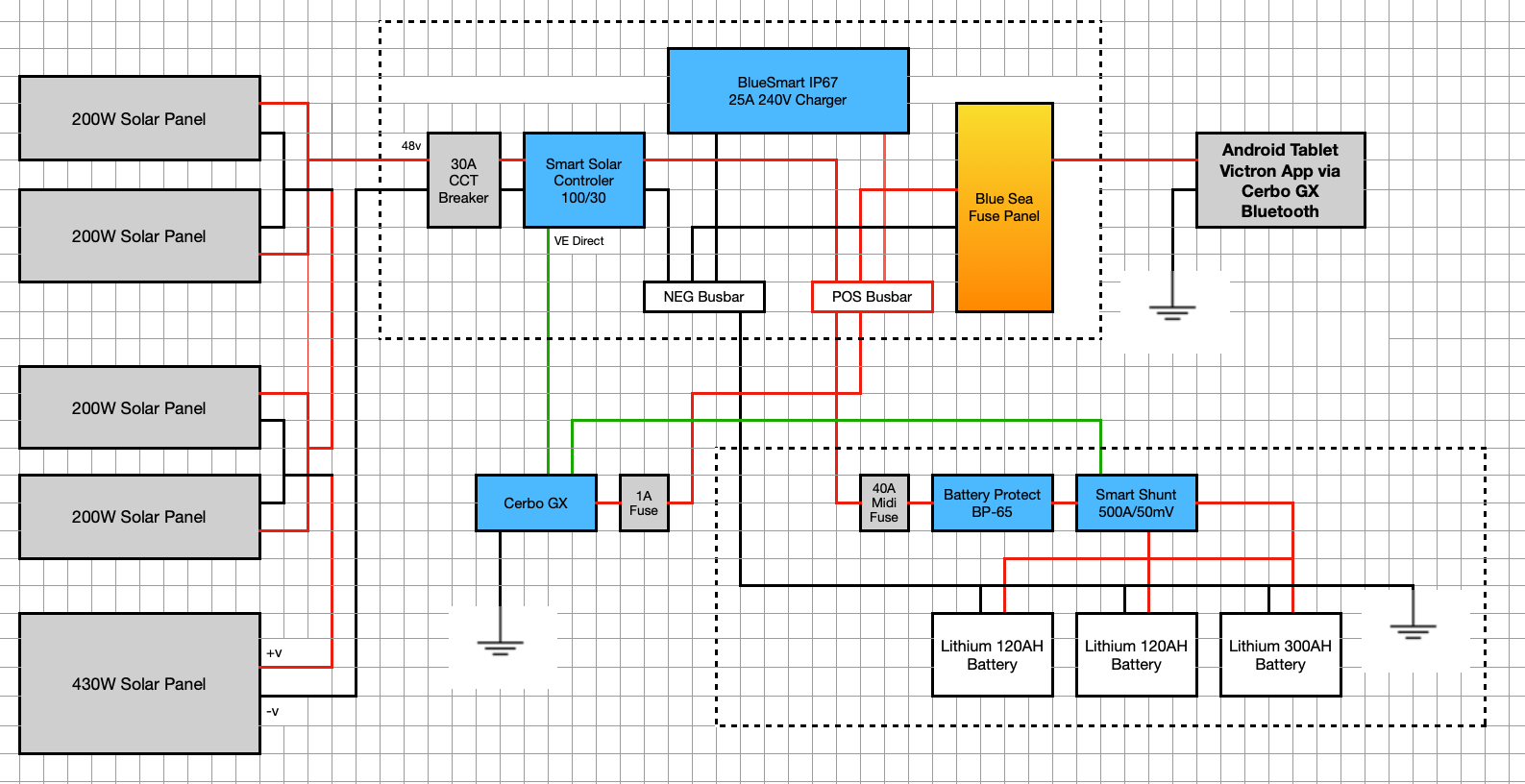
asked
New Caravan Setup
You should not mix up different solar panels in such a way. This will cause problems for the MPPT.
The possible power output of this panels might be way to high for the MPPT. According to Victrons datasheet, for a 24V system the recommendation is max 880Wp for the 100/30 charger.
You say it is a 48V system, but as far as I know there is no BlueSmart IP67 charger for 48V systems.
So what is the system voltage you are planing to have? 24V or 48V ?
And one more very important point, - the Smart Shunt must be installed in the negatibe path, not in the positive.
So far my quick feedback.
I missed the line about the smart shunt being on the negative side, I have now found the installation guide, will move it to the negative side, thank you.
In regards to the voltage being too high for the MPPT i have now provided a better explanation (below) and believe I am within the parameters?
Hi @egaryw
EDIT: sorry just seen the reply above already covers most of these.
Looks good to me. I work more on house installs so these features/suggestions might be overkill/not relevant for you but here's a few smaller things I'd maybe consider adding.
1. For house installs mixing panel sizes and the overall relatively low voltage of PV side is unfamiliar to me. However I would fuse each panel that's connected in parallel, I imagine this is even more useful if you're mixing panel sizes just incase they aren't 100% compatible.
2. I'd also add a few more disconnects/fuses between MPPT + main bus bar and the charger and the main bus bar. Fuses just in case, but the disconnects however would just make working on the system a little easier if you ever needed to. ie you could upgrade/remove Charger without losing solar while installing or vice versa.
3. Not sure if having battery protect changes this but I always install smart shunt on negative side of the battery. (Looks like
4. I've not used battery protect before but i believe it protects the overall battery however I personally also like to fuse each battery pack in parallel for some added protection. Especially given you have uneven capacities.
My (very paranoid) logic/scenario is say the internal BMS of battery 2 for example, for whatever reason detects a fault and disconnects that battery from the pack. If there's no coms between BMS and gx setup there's a chance you wont notice this straight away. If BMS stays off then all is fine and you'll just likely spot lower capacity eventually and look into resolving the issue.
However I'm always worried that the other 2 working batteries will continue to fully charge and then suddenly the broken battery's BMS resets and you have inrush current into the pack.
Extremely niche scenario/series of unfortunate events to get in that scenario so not the end of the world to leave out (ie need fault BMS to turn off at low charge and "fix itself" after a day of charging). The risk is also smaller if lifepo4 as you really do need big difference in SoC for there to be any form of sizeable inrush current between cells. If you packs doesnt have an internal fuse and you've got the room I'd maybe chuck some in just incase.
5. Those lithium batteries' are 48v each right, wired in parallel? If so that's a lot of capacity just to put behind a 40amp breaker. You might want to upsize the cable/breaker on battery side to future proof with a battery that size. ie would take ages to get through a full battery if you're limited to 40amp. (540ah/40 =13.5 hours running at full whack, which I'm guessing would be infrequent). Again my view might be skewed coming from primarily hybrid house installs but I'd personally put a larger breaker on that (assuming wire sizes upgraded appropriately) so you can draw more in one go given how much capacity you've got in storage.
Thanks Matt, I have added additional fuses for the batteries and 1 x cct breaker for the PV, as the panels are on a caravan its easy to disconnect each one individually if need be. The load in the caravan should not exceed around 20A, that is why I have a fuse @ 40A. @ 20A I should get around 27 hours at full whack :-), however, I am looking at installing an inverter in the future wired directly to the shunt and they suck out a lot :-)
As above plus
Power the Cerbo from the busbars.
Use a second controller for the larger panel. Make sure the panel voltage is high enough, assuming 48V batteries, you're going to need about 63V or more. For the smaller panels also make sure you're in the same voltage range, wiring pairs as above, you're looking for 63V or more again.
Dont put the battery protect in series with the battery. The battery protect is a one way device, to protect your battery from being total discharged. I would put it in serie with your fuse panel insted.
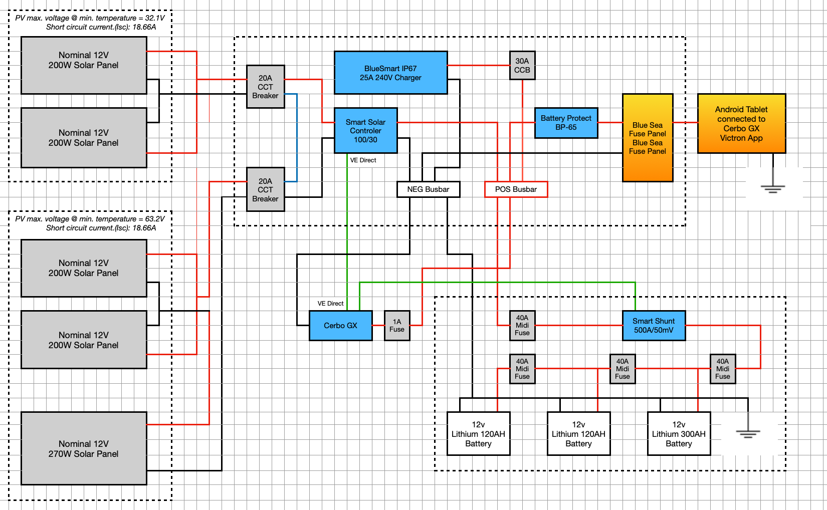
Wow, thank you all for your comments and advice, much appreciated it, I have incorporated as much as I can;
1 - Taken the Cerbo GX to the Busbar
2 - Moved the Battery Protect to the load
3 - Added additional CCT Breaker to the PV
4 - Added additional CCT Breaker to the 240v charger
5 - Added additional fuses to the batteries
6 - Fixed up my own typos :-( the larger panel is only 270W
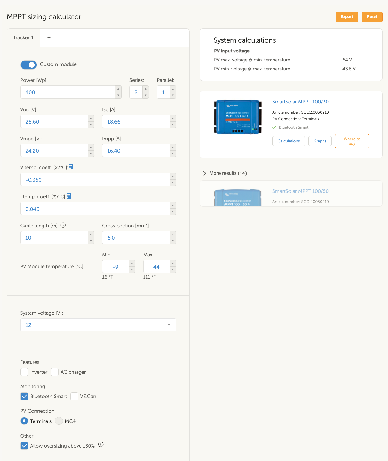
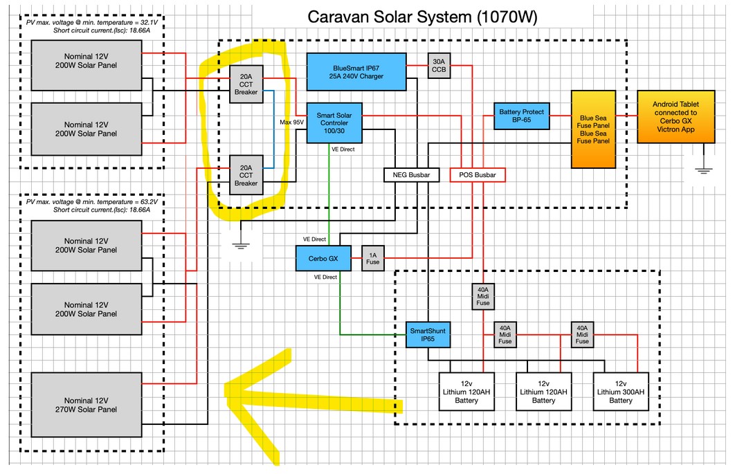
In terms of the panels, I have put more detail in as I neglected to show their V and A. All the panels are the same brand and voltage (the larger one delivers more current). I used the Victron MMPT calculator to size up the MPPT controller allowing oversizing 130%. I have basically 2 banks in series, one has a max Voltage of 32V delivers 9.33A and the other 64V delivers 18.66A, as they are in series the deliver max current should only be 18.66A with a voltage of 95V.
I only see one issue, if it is an issue? In the second bank, I have 2 in parallel which = 32V x 18.66A and the larger panel in series taking it up to 64V, in terms of the additional current, I am not sure if it limits the panel bank down to the 12.64A of the larger panel or I take the max of the parallel panels being 18.66A
Ver 2
Each string must put the same voltage to the MPPT. Your string with three panels has an odd wiring diagram. I can't work out what's happening there.
Regarding the second bank, the 2 x 200W are in parallel (400W) both are the same voltage = max 32V 18amps which are in series with the 270W max 32V 12amps.
The whole second bank = 670W max 64V 18amps
The 2 banks are then put in series to achieve a max 95V 18amps.
In regards to the strings going into the MPPT being the same voltage, as they are in series there is only 1 string @ 95V?
The 270W panel will restrict current with your proposed setup. I'm not sure by how much or if it will be damaged.
If I read your schematic correctly, your batteries are in parallel for 12V. The second number in the MPPT is the output current at battery voltage.
You thus won't achieve much more than 400W as the MPPT will limit the system.
Also here is a probable risk of exceeding the MPPT Isc rating.
You have/propose 1070W of panels. Into a 12V system at 14V, it's a current in the region of 80A. Even if you assume over panelling of 30%, you want to push about 60A through the output of the MPPT.
Thanks again, this is where I am a little cloudy so I will give you my thought process and let me know where I fall into a hole :-)
Firstly the MPPT controller input can handle 100V
With that, I used the Victron MPPT calc to calc the size using worst case @ -9 degrees celsius (in Australia we will never get that low anyway) The calc came up with 96V for 3 panels in series (all the panels are the same voltage Vmp 24.2v )
Each of the 200W panels deliver an Isc of 9.33A meaning that when in parallel they can deliver 18.6A MAX and the larger panel larger panel can deliver Isc 12.44A.
So effectively I have 3 banks in series -
1 - 200W x 2 (paralleled) = 32v 18A (MAX) @ -9 degrees celsius
2 - 200W x 2 - (paralleled) - 32v 18A (MAX) @ -9 degrees celsius
3 - 270W x 1 -32v 12.44A (MAX) @ -9 degrees celsius
In terms of the voltage I have confidence that the MPPT will handle the input, and I assume the total current available will be 18A or will it be reduced to 12.44A? Thats the cloudy part for me? In either case the MPPT Isc is rated at 35A so I expect either will be okay for the MPPT controler, what I dont know is how the total current available is calculated in this case.
In terms of the other issue you raise, the 80A and 60A situation, the MPPT controller will only deliver a max of 30A which is around 420W @ 14v, if there is additional power available it will be disregarded. By adding the extra panels will enable the batteries to be charged better on cloudy days or when the caravan is partially shaded.
Perhaps the 1070W was a little misleading, that number is merely all panels wattages added together.
I hope that makes sense, I would be interested in your thoughts?
Not sure why you're doing it this way. Doesn't make sense. You have a serious mismatch in your design. As the others have also pointed out.
Thanks Kev, looks like I will take out the 270W panel as I have no room to add another panel nor another MPPT controller. That way all the panels are matched properly. Is there any documentation that can calculate the max Isc in a panel array? Or are my assumptions above correct?
You have two strings of 2 panels. Each string has an Isc rating of a single panel. Multiply by the number of strings
You should have a temperature current factor. Use this to calculate the increase in current at max panel temperature less 25C. Max panel temp will be well over ambient. But it's an educated guess
If you're close to the controller limit, fit an inline fuse into each string, but these generally aren't needed until you have three panels or more in a string
As others recommended, use the Victron online calculator. But this works on an overpanel % of 130%, so will recommend a larger MPPT.
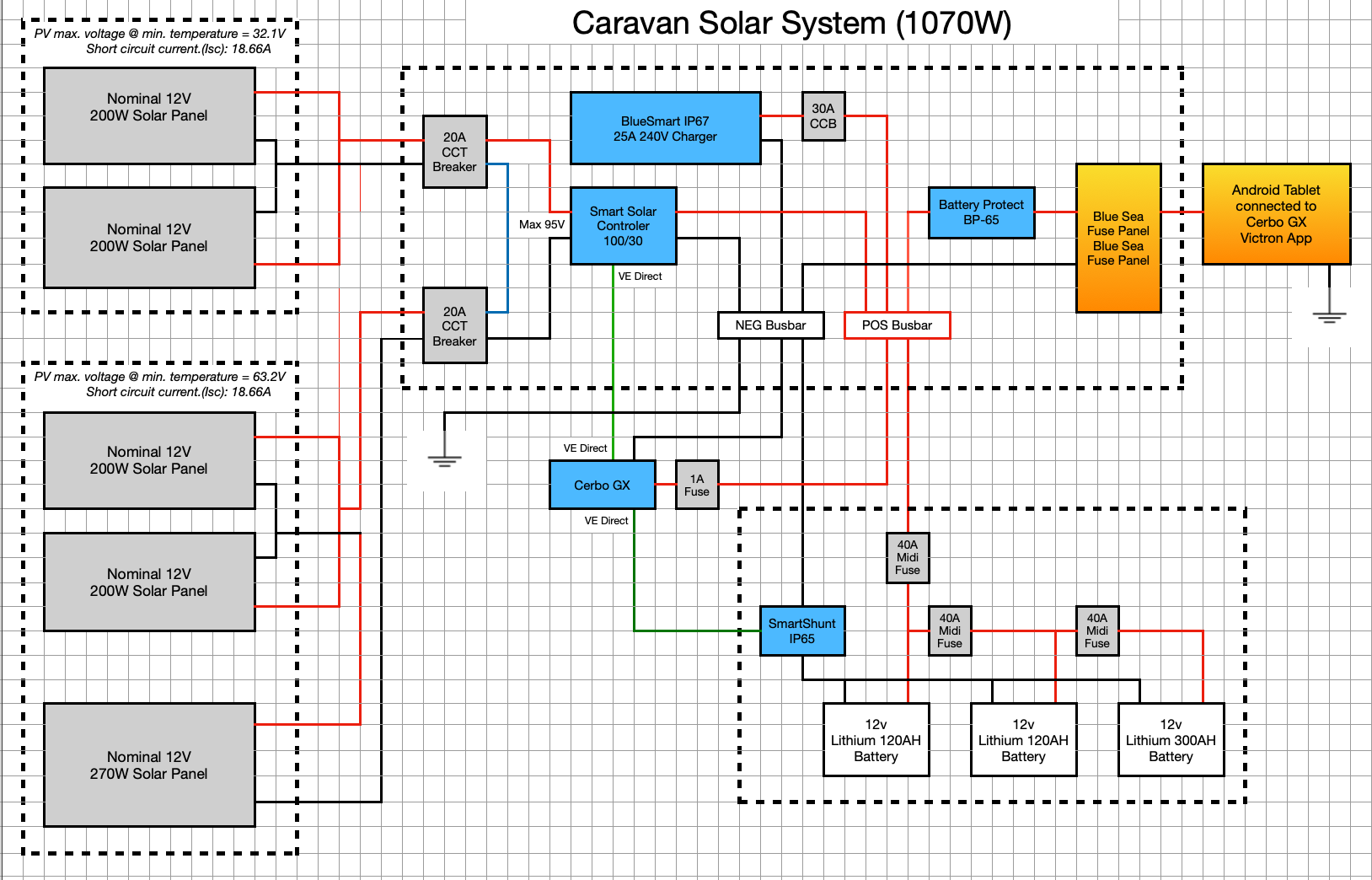
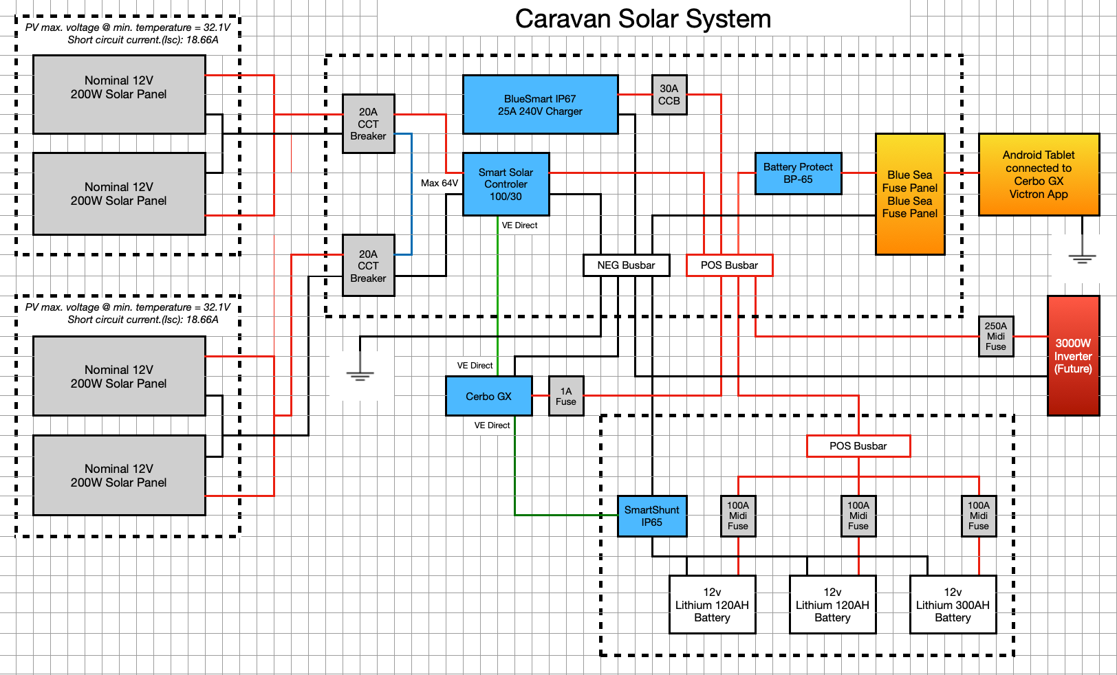
I neglected to place the Smart Shunt on the neg line, I think this is the final version (fingers crossed) unless I have missed something else?
About your pv setup, I would connect the 200w panels 2 in serie and then in parallel to your existing controller, and get yourself another controller for the 270w panel. Your sugested setup with a pv voltage around 95V is to close to the controller max at 100V. The 95V pv voltage would be at STC witch is at 25 degre celsius. The voltage will increase with lower temperature.
Another isue is your connection and fusing of your batterys. Why have 40A fuse in series.
You should connect your 3 batterys direct to the busbar so they are in parallel and fuse individualy. If you use the corect wiring you could fuse each battery with the spec of the battery insted of a 40A fuse, witch in my opinion is much to low.
Thanks Sten, for the batteries, I agree and will take them directly to the busbar, however I am interested why you think 40A fuses are too small. The load on the caravan will not exceed 20A?
Hi
@egaryw I'd agree with Sten but my reasoning is purely future proofing for larger loads/battery capabilities. You cells will likely be able to handle 0.5C easily (if they're LiFePO4). That'll be 60amps per pack and thats conservative for Lifepo4
My only other spot is likely just the way you've draw it. The battery fuses look like Fuse 2 is behind Fuse 1 and Fuse 3 is behind fuse 2.
if fuse 1 -> fuse 2 -> fuse 3.
Rather than:
Battery bus bar -> Fuse 1
Battery bus bar -> fuse 2
battery bus bar -> fuse 3.
But I'm guessing that's just the drawing software rather than a mistake.
Hi Matt, yes your right, I have altered the drawing for better understanding and increased the fuses as per your recommendation,

Great drawings btw. What software is it out of curiosity?
I'd still throw some inline fuses between the parallel strings of panels but the rest looks good. As i said it's odd for me to see missmatch panel sizes but I've only ever done houses.
Thanks :-) Its just the apple numbers program which is similar to excel.
In terms of placing fuses in the panels, are you able to purchase in MC4 line fuses?
With 40A times 3 it is better (120A), but I think most lifepo4 dropin batterys at around 100Ah 12V have a BMS that can deliver something like 100A, so why not design the system to this. That would be 300A insted. Then you can easey add an inverter later without a redesign of your system.
Thanks Sten, yep understand your logic, however the voltage is calculated at the MAX voltage @ -10 degrees celsius = 95V. With that in mind is there any other reason that the PV arrangement will not work?
@egaryw Your PV breakers are doubled up for no benefit.
Again you SHOULD NOT have the 270w panel in series with the 2s x 2p 200w panels. To have panels in series their Imp/Isc has to match.
Thanks Klim, yep after accepting all the information I will take out the 270W panel. I have not found any documentation on the Isc being matched or calculated in terms of a panel array for either series or parallel configurations (still looking). Can you point me in the right direction?
The additional cct breaker is for disconnection purposes mainly.
 Final config again :-) thanks to you all for your input
MMPT input MAX (100/30)
Voltage Voc = 64v @ -9 degrees Celsius and Current Isc = 18.66 amps (MMPT max Isc 35A)
The biggest pickup on this was learning that the MPPT actually short ccts the panels to stop the charge, now I understand why the Isc is so important. thank you.
The MMPT calc on the config 2 x 400W panels in series for completeness.