multi plus 2.pngI am building a system for my RV. I currently am running a 30 amp system. I plan to replace the distribution box and convert to 50amp split phase service. I want to install two Multiplus 2 units and run them in split phase. The 48/5000/70 model.
Multiplus 2 link:
https://www.victronenergy.com/inverters-chargers/multiplus-ii#manuals
I will be using 48volt EG4 lifepo4 batteries. 200Amp internal BMS
EG4 Lifepo4 link:
https://signaturesolar.com/eg4-wp-lithium-battery-48v-100ah
I will be using the Westinghouse 12000 running watt 15000 starting watt generator with remote start and auto choke to charge the batteries. (Eventually I will be adding solar panels and only using the generator as a backup, although thats not too relevant to my inquiry here, essentially I’m going to be using the backup system as the main system until I can afford the rest of the equipment).
Westinghouse Generator
https://westinghouseoutdoorpower.com/products/wgen12000-generator
And I wanted to also use a 100amp Victron Autotransformer. I want to use it to balance my split phase loads. (sometimes I will want to use it in conjunction with the Multiplus Units running in parallel rather than split phase to accept 30amp shore power but output split phase power for my distribution box. I know this requires a different wiring set up and hope eventually to understand this Autotransformer well enough to craft up a clever design where I only need to flip a switch, or a few, to switch between balancing mode and step up mode. For the purpose of this post you can just focus on my desire to use it for split phase balancing. Thats the wiring I’m trying to currently understand.)
The generator will be wired to the two inverters in split phase, the autotransformer will be wire to the output of the inverters, and the auto transformer output will go into the distribution box. The auto transformer will be used to balance loads when drawing from the battery and inverting the DC to AC. The autotransformer will be used to balance loads when using the generator to charge the batteries and simultaneously powering the RV loads.
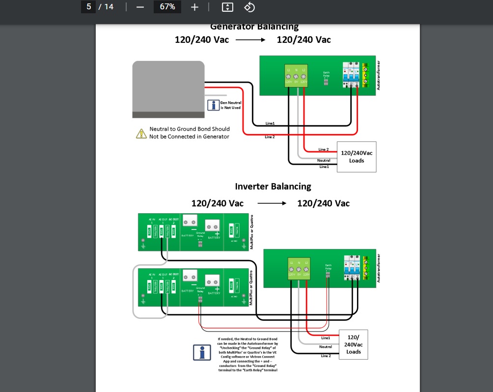
My question is about the proper way to wire this. I have read the manuals of the Muliplus 2 and the Autotransformer. In the auto transformer manual in the balancing section there is a diagram for inverter balancing, and there is a diagram for generator balancing. The wiring is different. However the diagram shows the generator connecting directly to the autotransformer with nothing in between. I wont be connecting it this way. The generator goes to the 2 Multiplus 2 units. And the Multiplus units go to the autotransformer.
Auto transformer link:
https://www.victronenergy.com/autotransformers/autotransformers#downloads
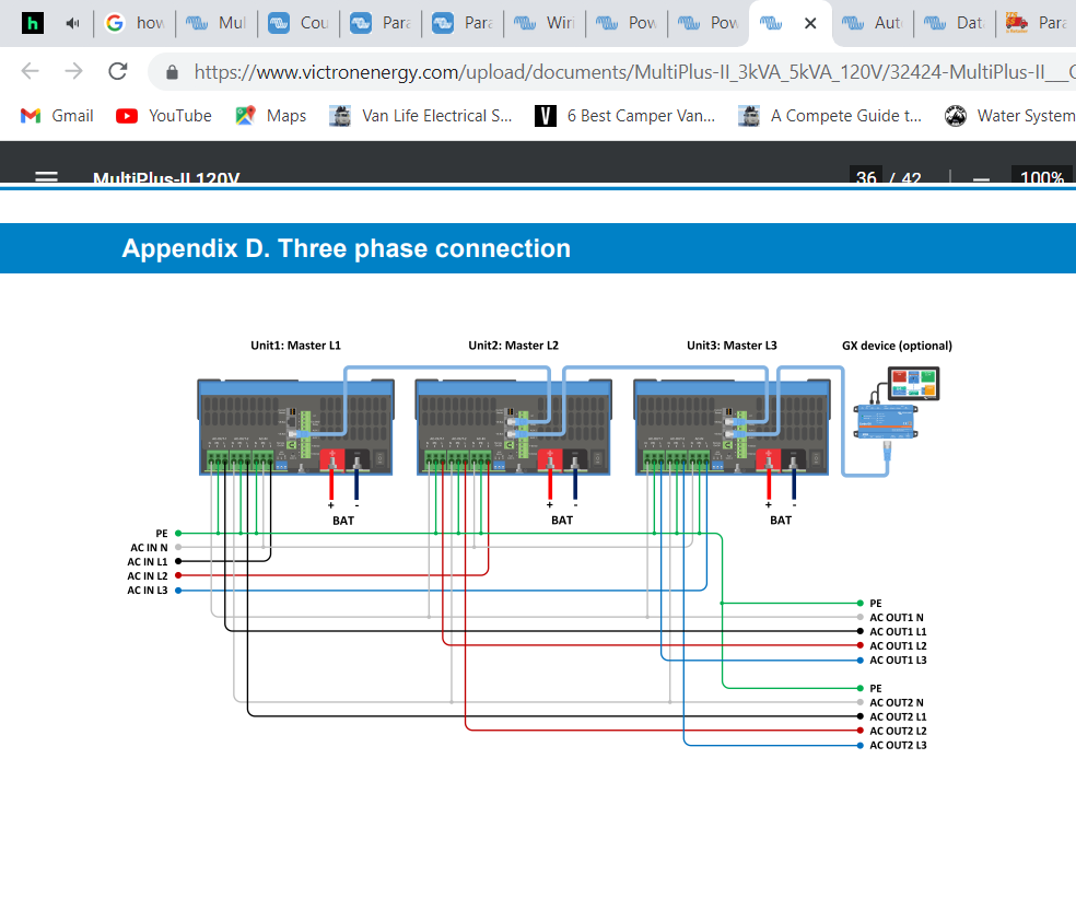
Do I just wire the system the way that it shows in the inverter balancing diagram? In the generator balancing diagram it shows that the generator neutral is unused. But I think the generator neutral still needs to be wired to the multiplus units the way it shows in the wiring diagram at the end of the Multiplus 2 manual (except there will only be 2 units, and 2 hot legs). And then I think that I would just wire the auto transformer the way it shows in the inverter balancing diagram. Can anyone speak to the accuracy of this? What is the right thing to do with the generator lead?
The other thing that concerns me is that in the generator diagram it says Neutral to ground bind should not be connected in generator. And I don’t fully understand what this means. Whereas in the inverter balancing diagram it says “If needed the neutral to ground bond can be made in the autotransformer by unchecking the ground relay of both multiplus’ in the VE config software or Victron connect app and connecting the positive and negative conductors from the ground relay terminal to the earth relay terminal.
I guess im not sure if these two things are contrary to each other.
Can someone please explain the function and how it works of the ground relay and earth relay? What is it really doing when I wire the two together?
Can someone please explain what the function of wiring the AC 1 neutral output of one inverter to the AC neutral output of the other inverter accomplishes? I thought it was strange to wire output to output. What is happening here? Is this a dangerous connection to make if I am wiring the generator ground into the multiplus units as shown in the multiplus wiring diagram appendix D.
Essentially I am trying to establish the propermulti plus 2.png wiring for the generator and autotransformer when the auto transformer is being used to balance split phase load and when the generator is charging the batteries and passing through the multiplus units power the RV loads.
Thank you for anyone who takes the time to look at this. I am learning more and more each day. Being very cautious to make sure I truly understand before attempting anything in the physical world. I have searched the questions and answers of this community and did not find something that answers my questions. I have tried calling victron dealers but a lot of them are lost the moment I mention the auto transformer and tell me theyve never used one.