question

Pete MacLachlan avatar image
Pete MacLachlan asked

Autotransformer voltage outputs are different

I am having an issue with the Autotransformer output voltages - 114V on L1 and 120V on L2 (with no load)

120V current is supplied by a Quattro 48V / 10000 / 140-100/100 to the 100A Autotransformer. I'm using the AT to provide a split-phase 120/240v supply to the 50A main break panel in my RV

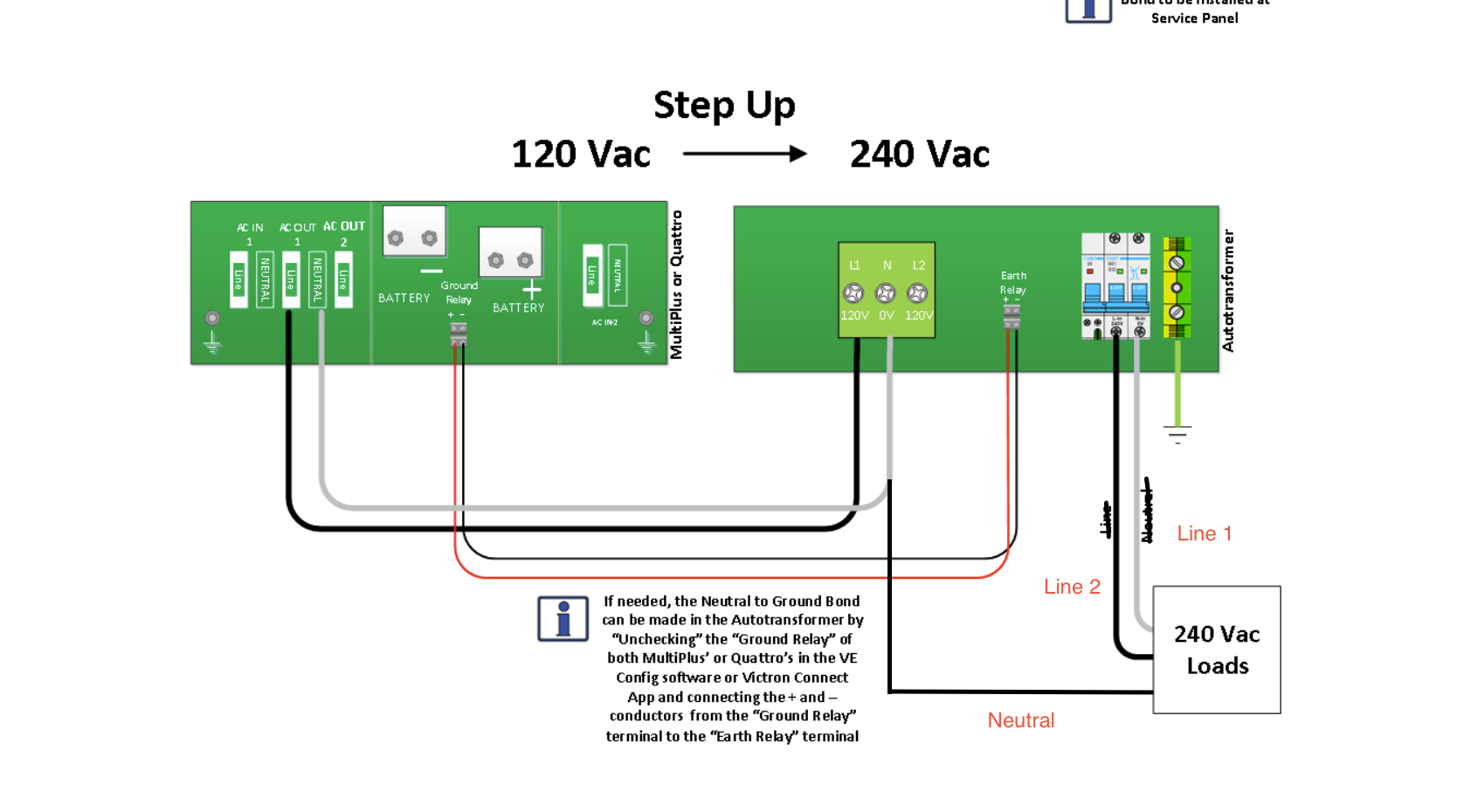
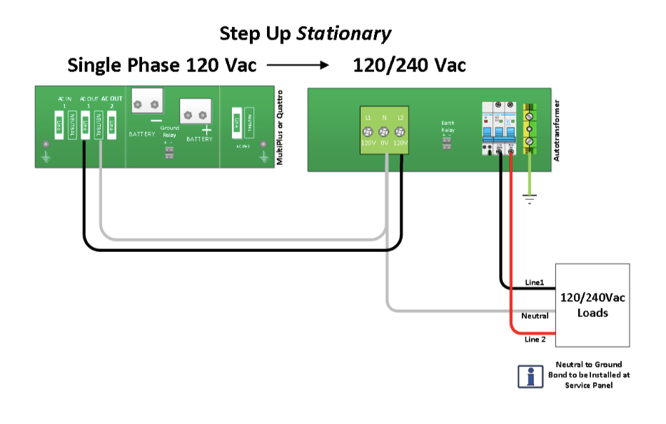
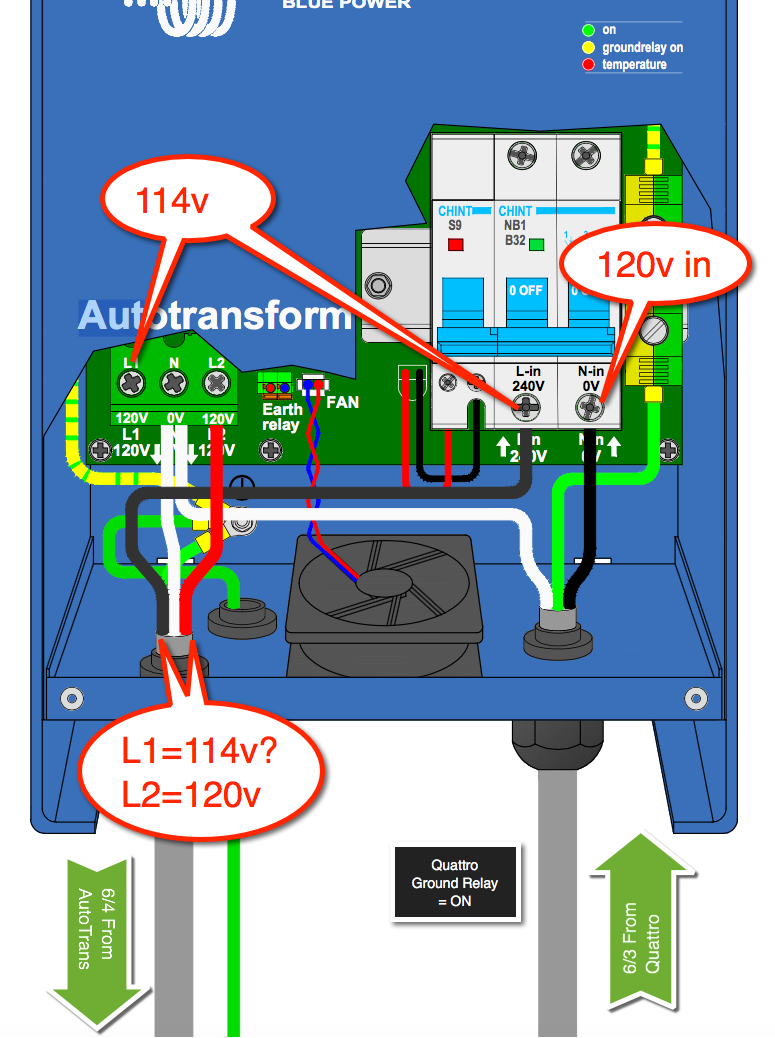
I have wired the AT connections according to the diagram #3 shown on the system schematics page from the Victron website: (https://www.victronenergy.com/upload/documents/AT-3-split-phase-120V-to-120-240V-with-Quattro-120V.pdf)

The Ground Relay in the Quattro is set to ON and is correctly grounding the Neutral to earth.

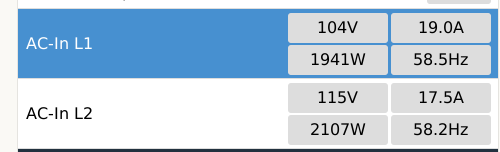
Here are the voltages I read at the terminals:


The problem I have with this is that the voltage on L1 decreases a lot with load, and when occurs equipment will pull more current to compensate for the lower voltage.

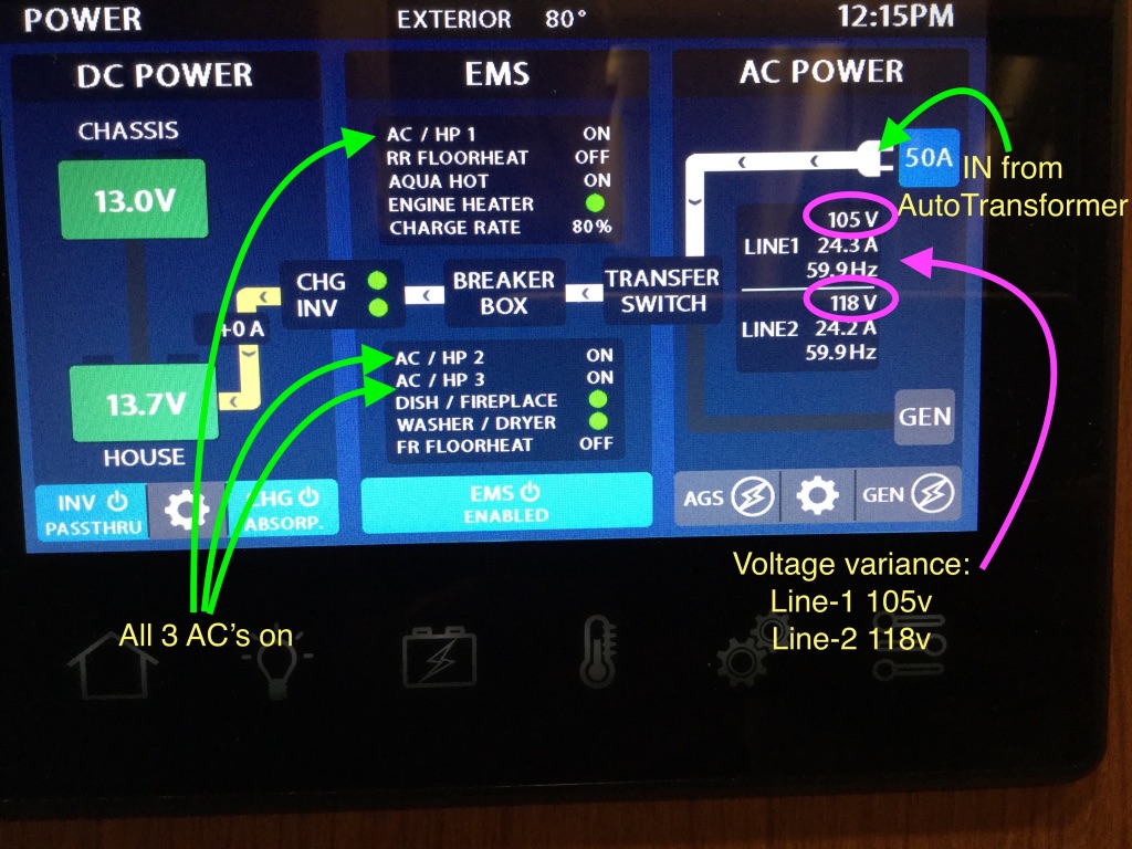
Here is a pic of my RV control panel, showing the disparity in voltage between L1 and L2. Even though there are 2 air conditioners on Line2 it has only dropped 2 volts - Line1 dropped from 114v to 105v. This can't be good.


Questions: 1) - Is this method of wiring correct, and 2) what is causing the voltage discrepancy?

Thanks!


Aug-31: Editing this in an attempt to make the question visible again. I'm thinking of sending this AutoTransformer back to Victron as it is not performing to expectations. I have seen voltages as low as 96 volts on L1, at which point my UPS shuts down my computer, and various other circuits shut down. Not happy...

I'd appreciate a comment from anyone who has had experience with an AutoTransformer.

voltageAutotransformersplit phase
2 |3000

Up to 8 attachments (including images) can be used with a maximum of 190.8 MiB each and 286.6 MiB total.

6 Answers
solardude avatar image
solardude answered ·

Are you 100% sure the ground relay is working? Did you flip the dip switch on the Quattro? Is the ground relay LED lit up? Can you hear it click inside the AT when it powers up?

2 |3000

Up to 8 attachments (including images) can be used with a maximum of 190.8 MiB each and 286.6 MiB total.

epuhs avatar image
epuhs answered ·

I'm using mine in a slightly different role, but observing the same L1 voltage drop both with and without the ground relay (verified on, via the LED).

The below screenshot was taken with power supplied by an Onan 5500W generator.


2 |3000

Up to 8 attachments (including images) can be used with a maximum of 190.8 MiB each and 286.6 MiB total.

blueovalbruin avatar image
blueovalbruin answered ·

Pete, did you ever get resolution to this issue?

2 |3000

Up to 8 attachments (including images) can be used with a maximum of 190.8 MiB each and 286.6 MiB total.

dbainbridge avatar image
dbainbridge answered ·

Can someone comment what the issue is with this? I'm hesitant to use the autotransormer if this is a common unsolved issue.

2 |3000

Up to 8 attachments (including images) can be used with a maximum of 190.8 MiB each and 286.6 MiB total.

irwinr avatar image
irwinr answered ·

I believe you're just witnessing voltage drop across through the transformer. Remember that only one leg actually flows through the transformer itself when using an auto transformer to step 120v up to 120/240v split phase. That is a lot of drop though and more than I see on mine (Though I'm using the Outback Auto Transformer rather than Victron)

The way an auto transformer works is it lets some power from your 120v source go directly to your loads. This forms either "L1" or "L2". I'll use "L2" in my example since that seems to match what you're seeing. In this case there would be very little voltage drop on L2 because it's not passing through the transformer coil at all. The current that does get passed through the transformer coil is effectively phase shifted 180 degrees, which gives you a 2nd leg of 120v that's 180 degrees out of phase with the other leg. This becomes your "L1".

Here's a picture from the Victron data sheet to illustrate: screenshot-2021-09-21-at-15-25-15-datasheet-autotr.png
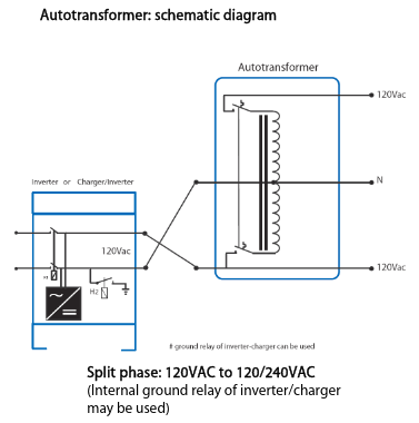
In the above picture it shows taking 120v from a 120v inverter and using it to generate 120/240v split phase. But let's just pretend that inverter is actually your Onan generator instead.

That top "120Vac" output in that diagram is your L1. The current on that line is created by current flowing through the bottom of the coil from the source 120v. That current creates a magnetic field which induces current in the top half of the coil that is the same voltage but 180 degrees out of phase.

The bottom "120Vac" output from the autotransformer is your "L2": Notice how it doesn't pass through the coil at all, and just flows straight to your loads? Very little voltage drop on that leg.

So you have "L1" which goes through the transformer and gets phase shifted 180 degrees: This imposes some voltage drop of not just going through the coil, but also some losses from the magnetic field being created and used to induce current in the other half of the coil.

"L2" however just goes straight to your loads: Much smaller voltage drop since it doesn't pass through the coil, create a magnetic field, or induce current in the other half of the coil.

If you have say a 5500 watt generator that puts out 120v, that's a total of about 46 amps. If you're pulling all 5500 watts from that generator through the auto transformer that means you have 23 amps flowing on L1 and 23 amps flowing on L2. 23 amps of current flowing through the auto transformer is going to cause some significant voltage drop on the "L1" side which is flowing through the transformer.


1 comment
2 |3000

Up to 8 attachments (including images) can be used with a maximum of 190.8 MiB each and 286.6 MiB total.

wolf avatar image wolf commented ·
Hi Irwinr, do you have a schematic for your system or would you be able to give me some pointers? Do you have a Insta, FB or any other? Thank you!
0 Likes 0 ·
sinyyl avatar image
sinyyl answered ·

I have an answer here. In another post, one said this is because the winding of the coils caused by the output to be -5%, you reverse the input/output side to get a +5% voltage output. For me, I have 120V on one L1, 113V on L2 at output (no load). Both of the 2 wiring scheme indicated by the manual about 120V -> 120/240V step-up will cause this voltage drop.

Instead, what you want to use to get a higher voltage is this in the manual (slightly modify it):

screenshot-2023-03-28-at-122423-am.png

By doing this, I get L2-N: 120V, L1-N: 126V, L1-L2: 246V. L1 is slightly high, but overall, for me it is much better than being 113 at no load. Under full load (32A for my 100A auto transformer), L2 drops to 118V. Still a very useful voltage.

Before I would not be able to get 32A because the voltage will be way too low at about 25A (~103V), also it created a lot of heat, tripping the breaker constantly. I tested this wiring about 20min with high load, no breaker trip.

My source of input is Onan 7500. About perfect size paired with this autotransformer. The total output is ~61A. Split to lines with the voltage boost, makes it 30.5A on each line at max load, and that is about the max transformed current the unit can do.


3 comments
2 |3000

Up to 8 attachments (including images) can be used with a maximum of 190.8 MiB each and 286.6 MiB total.

gutzpowers avatar image gutzpowers commented ·

Has anyone else tried the configuration @sinyyl mentioned above?


Edit: found this video with a similar install that @sinyyl mentions: https://youtu.be/cHrEYTMsn9w


0 Likes 0 ·
sinyyl avatar image sinyyl gutzpowers commented ·
I watched the video, it is the standard way of wiring mentioned in the manual, not what I drew above. Feel free to bench test it, it worked well for me for now.
0 Likes 0 ·
gutzpowers avatar image gutzpowers sinyyl commented ·

@sinyyl You mean this is the right one, correct?


61e81e5e-bfbe-4e34-89b2-e0a69a88bc1c.jpeg

0 Likes 0 ·