question

cookinwitdiesel avatar image
cookinwitdiesel asked

Using AutoTransformer to create 120v/240v split phase from single phase 120v input

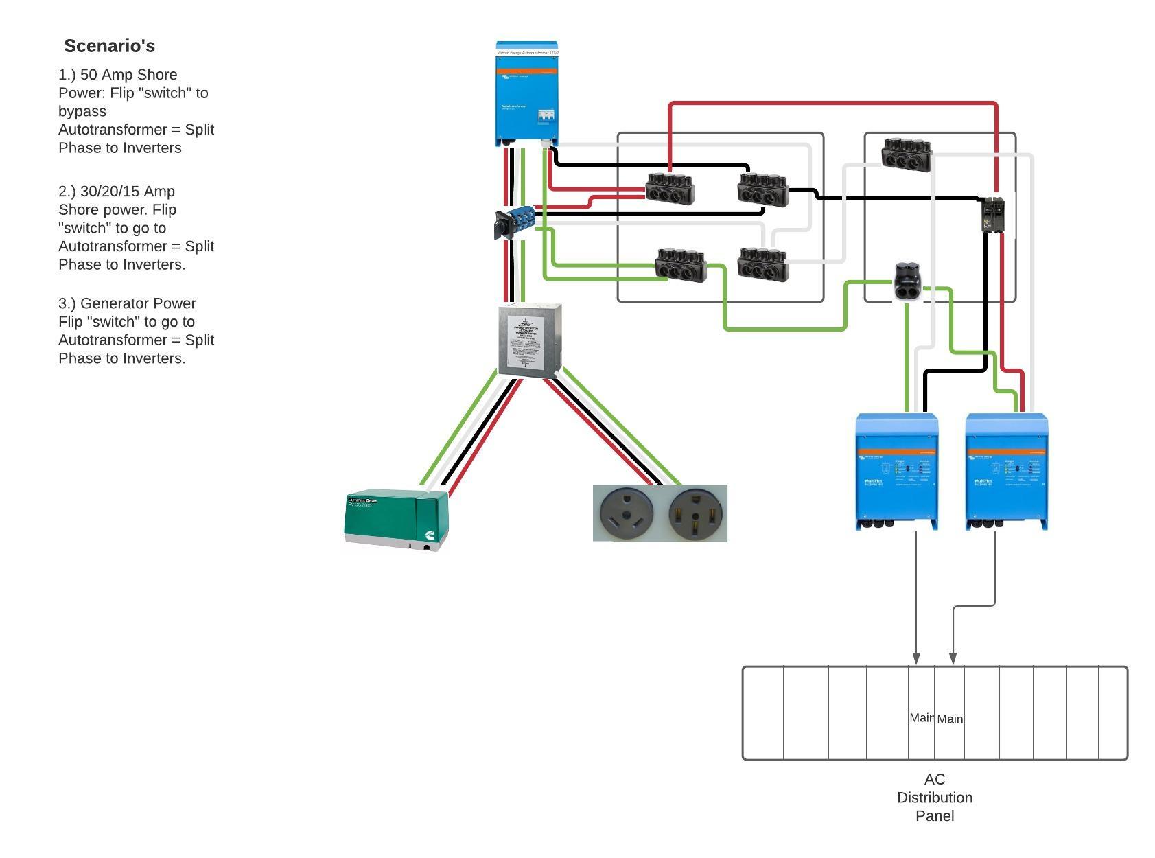
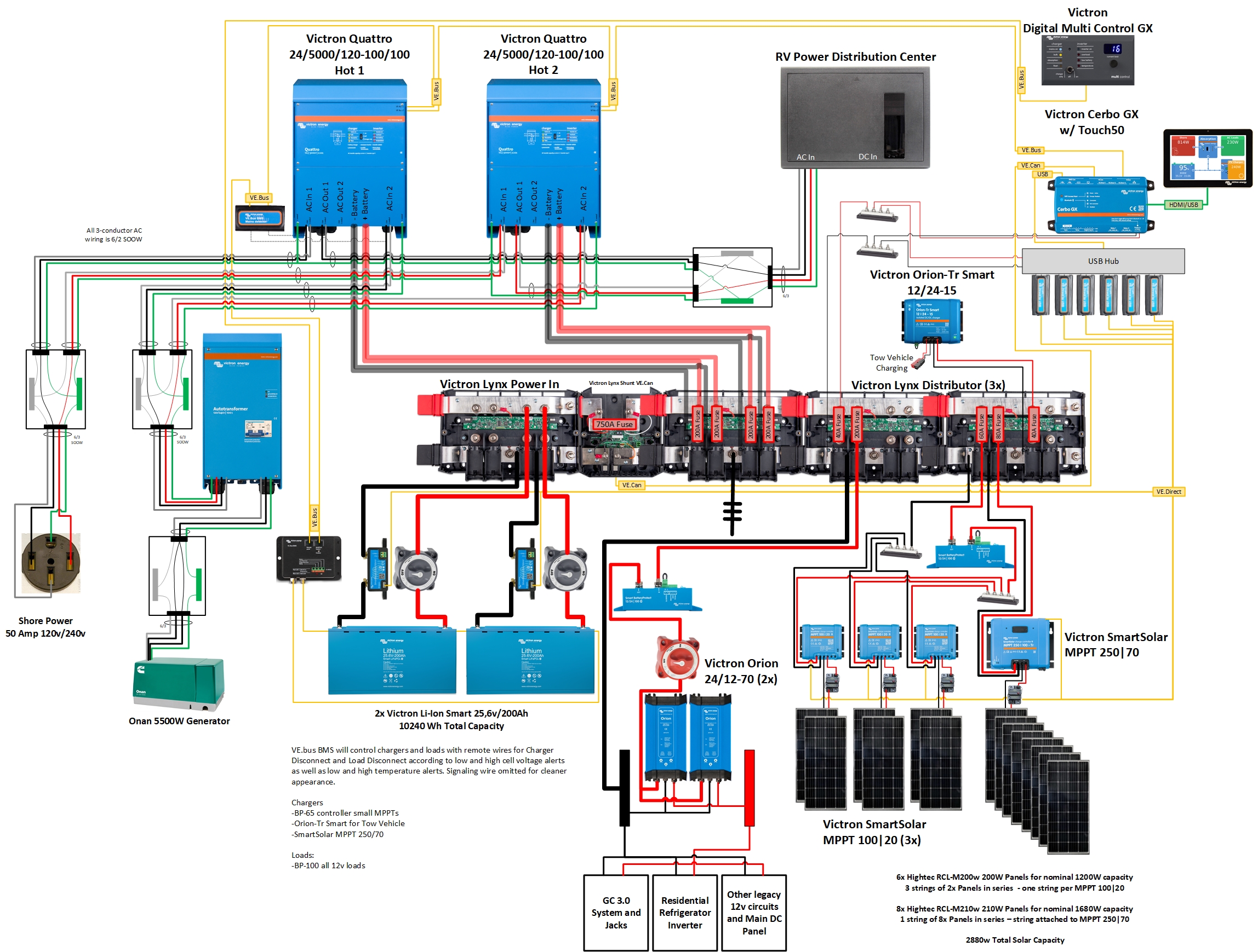
I have a use-case for the AutoTransformer that is different from what I see generally discussed. I want to use it in my RV to take in 120v 60 Hz from either my Onan Generator (2 separate 120v legs that are SAME phase) or the shore power inlet (30/15 Amp which are 120v 60Hz single phase). I have those 2 inputs going to an automatic transfer switch so whichever one is "on" will pass through to the AutoTransformer. I would like for the AutoTransformer to step up the voltage from 120v single phase to 120v/240v split phase. I will then pass that split phase into the input side of my dual inverters (one inverter for each 120v leg) so that when I have a single leg input, I still get both inverters charging instead of one side passing through voltage and the other rejecting the phase and inverting to make the "correct" phase.


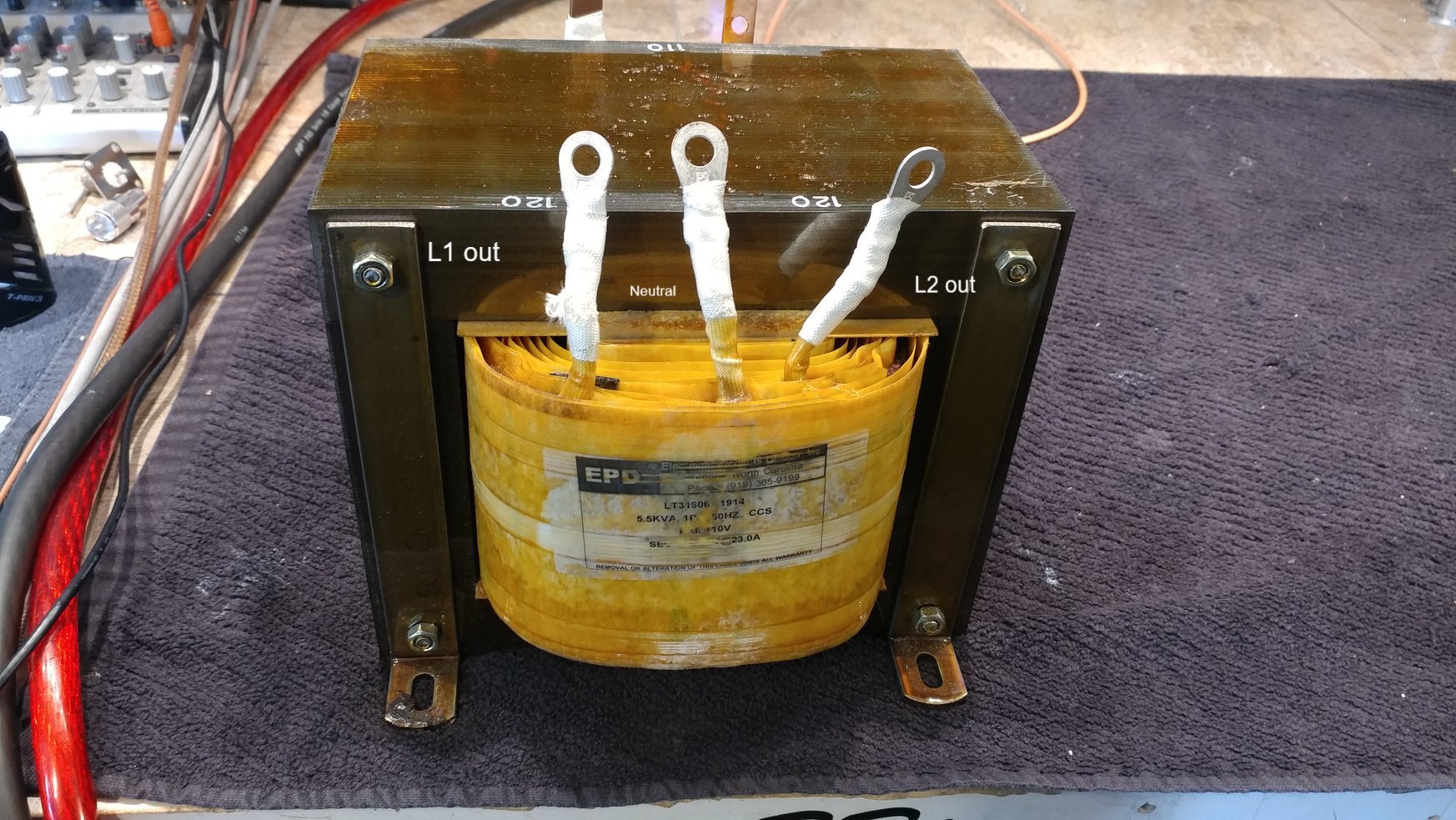
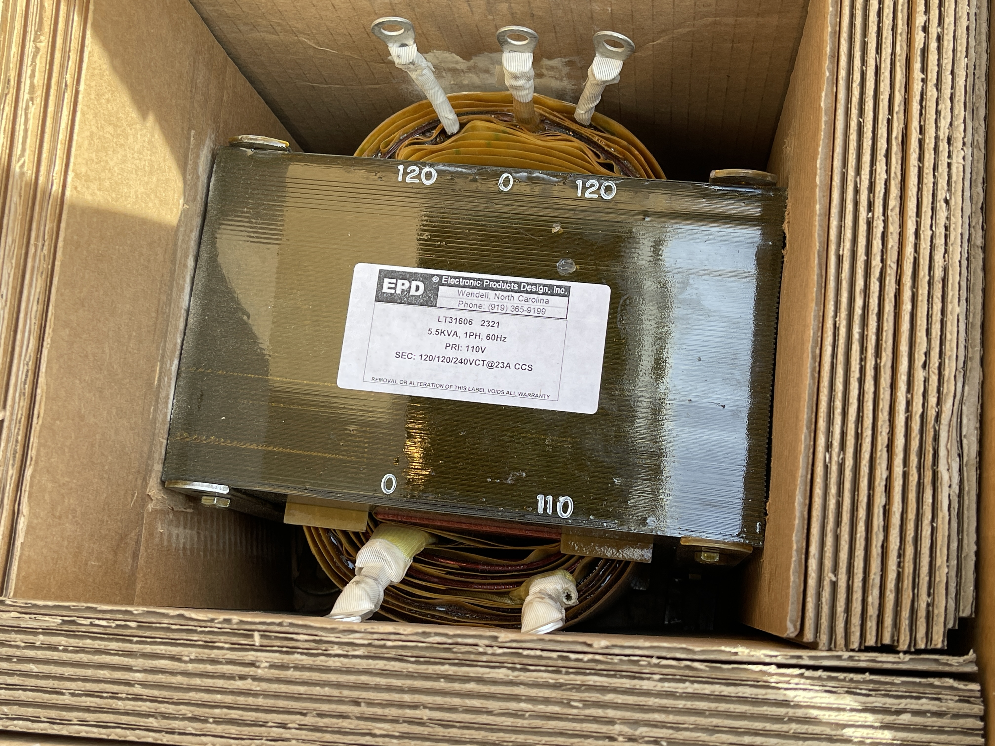
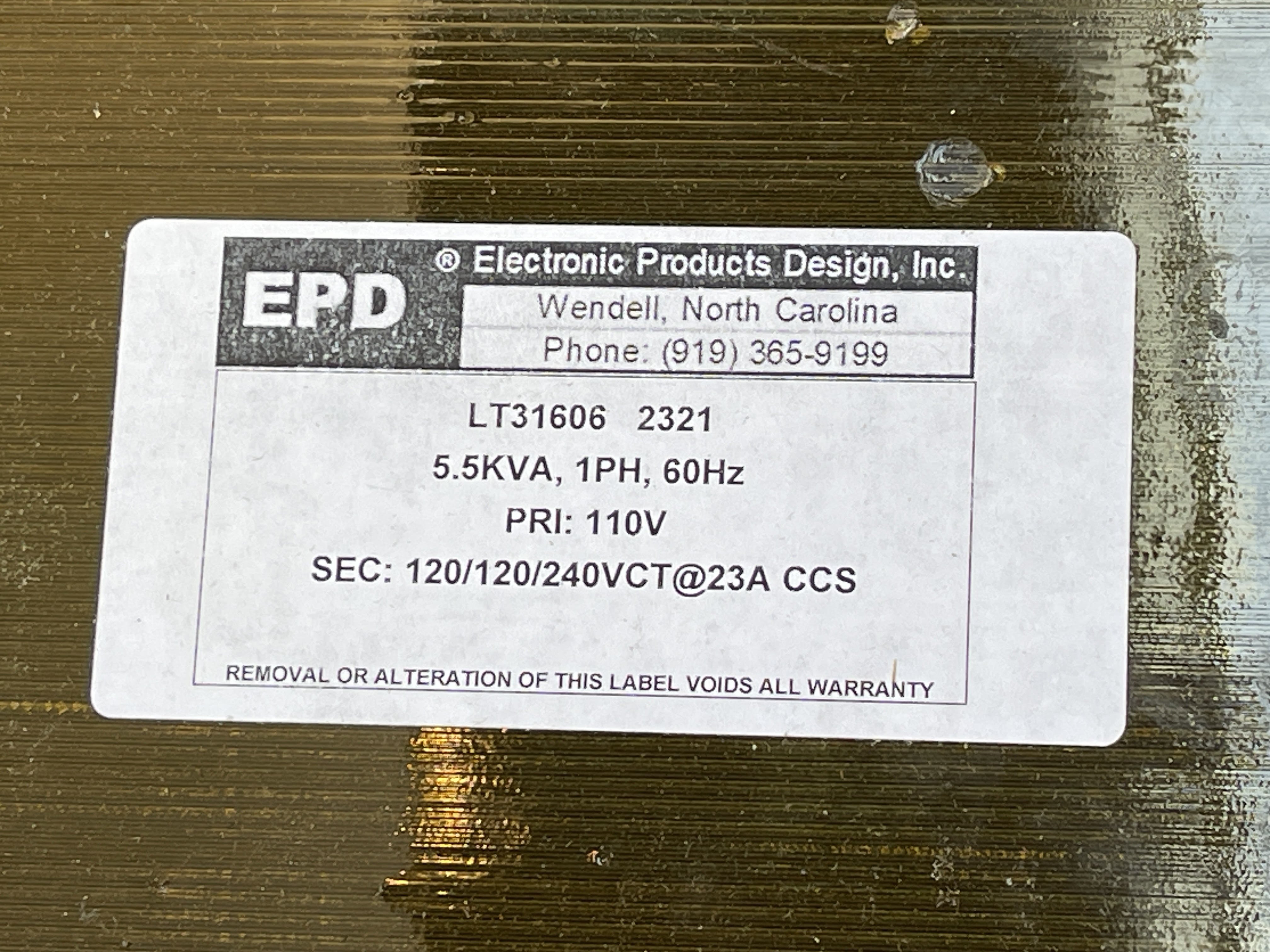
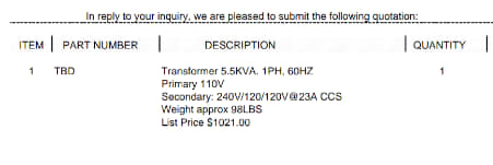
So, my question is, how should this be wired up to the inverter. It has labeled "input" and "output" sides but the "input" side only has 240v Line and Neutral labeled connectors. The "output" side has 120v Line 1, Neutral, 120v Line 2 connectors.


My intuition tells me to disregard the input/output labeling and connect my source 120v power with:

source 120v Line > AutoTransformer "output" Neutral

source Neutral > AutoTransformer "output" 120v Line 1


Then my output would be the 240v wave form stepped up via transformer as measured between the "input" Neutral and "input 240v Line connectors. I would need to carry over the neutral from the other side to provide 120v/240v split phase.


It is this last part I am unsure of and need some guidance on.

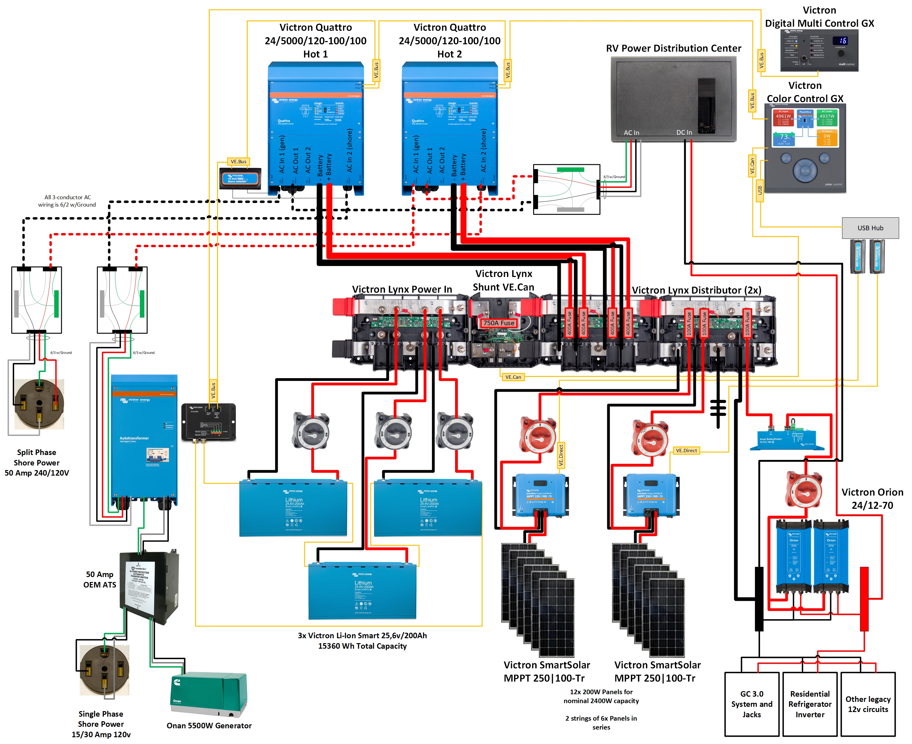
Diagram attached of my planned whole system that hopefully makes clear what I am trying to achieve.


Thanks!

Autotransformersplit phase
2 comments
2 |3000

Up to 8 attachments (including images) can be used with a maximum of 190.8 MiB each and 286.6 MiB total.

wolf avatar image wolf commented ·

This looks really good. I am looking into doing it and I would love to do 24v but with the fifth wheel we own using 12v everywhere and the generator also being 12v for starter battery it seems like a right to go to 24v and then come back to 12 plus add a separate 12v starter battery, a step down converter and a battery charger for the 12v battery. Having a 12v battery bank simplifies everything and reduces the amount of equipment plus if something goes wrong you can always just tap into the battery straight for 12v.

0 Likes 0 ·
cookinwitdiesel avatar image cookinwitdiesel wolf commented ·

I ended up adding a lawnmower 12v AGM battery that I maintain with a Orion 24/12-9 as a small insurance policy. All other 12v loads are converted from the main bank though and controlled by the BP-100 wired to the BMS load disconnect. I do not have the 2nd inlet as for the time being I am ok with having one inverter accept shore power and the other inverting. The conversion loss I would incur is fine given the simpler and lighter system.

0 Likes 0 ·
5 Answers
Johannes Boonstra (Victron Energy Staff) avatar image
Johannes Boonstra (Victron Energy Staff) answered ·

Your intuition is right, So disregard the input/output labeling and connect the source 120v power with:

source 120v Line > AutoTransformer "output" Neutral

source Neutral > AutoTransformer "output" 120v Line 1


Form the other Line the 240Vac towards the L in out will appear

5 comments
2 |3000

Up to 8 attachments (including images) can be used with a maximum of 190.8 MiB each and 286.6 MiB total.

cookinwitdiesel avatar image cookinwitdiesel commented ·

Thanks for the confirmation!

Something to note for others interested in the same configuration, your input 120v power will be limited to the rating of the neutral windings - in this case, 28A continuous and 32A for a short period of time.


It is a shame that Victron did not use a heavier duty transformer/wiring to allow for greater neutral current - 50A would be ideal I think.

0 Likes 0 ·
jetwire avatar image jetwire cookinwitdiesel commented ·

Did you ever get this setup going? I have a very similar setup. Do you wire both 120V legs from the generator to go through the Autotransformer or can you send one of the generator legs straight to one of the Inverters? On another forum someone mentioned only passing one of the legs through the Autotransformer to "flip" it 180 out. By doing that would you be able to pass 60 amps total? (Both generator Legs) Or would you still be limited by the 30A Autotransformer neutral limit? I have an Onan 8000w with the same 120/120 single phase and will be using 2 Quattros and want maximum generator power available if possible.

0 Likes 0 ·
cookinwitdiesel avatar image cookinwitdiesel jetwire commented ·

I did finally get this completed earlier this month. I bonded the 2x 120v legs from the generator together before feeding them through the autotransformer. If you study the wiring carefully, you will note that only one leg actually goes through the coil, the other is pretty much passthrough with just a breaker added. So if you pass it through or run the first leg outside the autotransformer really doesn't change much.

0 Likes 0 ·
jetwire avatar image jetwire cookinwitdiesel commented ·

Interesting. So with it setup like that you aren't limited to 30A total from each "leg" of the single phase generator? I ended up finding a company to build me a custom Autotransformer for the Generator. Since I already had the Victron AT, I ended up using it to balance the loads coming out of my 2x Quattros. Lots of $$ in transformers but the whole setup is working great!

0 Likes 0 ·
cookinwitdiesel avatar image cookinwitdiesel jetwire commented ·

My generator outputs about 23a on each "leg" but they are the same phase. So I bonded the outputs together and have a single 120v (up to 46a) feeding into the autotransformer. Only half of that power however rides across the coil which has the 28a limit

0 Likes 0 ·
cory cantrell avatar image
cory cantrell answered ·

I have a similar question, as to how to wire an autotransformer to convert the 30amp AC shore connection to split phase, and the generator to split phase to power the entire coach with dual inverter.

i also want to run my inverters in split phase, but I don’t want to lose any ability when on 50amp shore power, I also want both inverters to work the same as they would on 50amp shore power. Hence my dilemm, seems very similar to yours.

I could really live without the 30a shore power getting turned from single phase to split phase and just allow the second inverter to invert and use battery for the second leg, but what I wouldn’t want is the inverters to do that when on Generator. if I put an autotransformer between the generator and the ATS would that suffice my requirement?

I am running dual multiplus not dual Quattro so don’t have the second AC in, and don’t want to give up anything on my 50amp shore connection.

23 comments
2 |3000

Up to 8 attachments (including images) can be used with a maximum of 190.8 MiB each and 286.6 MiB total.

cookinwitdiesel avatar image cookinwitdiesel commented ·

Yep, 50a 120/240v RV system.

You are thinking about it correctly I think. I would go 120v Generator Autotransformer > ATS > AC input on MultiPlus

You can then accept 30a 120v input to a single inverter while the other inverts from battery OR have an additional switch that you can use to pass the 30a 120v input through the Autotransformer as well. @Natebert added a switch like I am describing to send 120v inputs through the transformer so he can hybrid boost on both legs in his system.

This is what I ended up building and other than a sizable voltage drop on L2 from the Autotransformer I have been very happy with it. For the autotransformer wiring, see scenario 3 from the Victron provided diagrams shown here:
https://www.victronenergy.com/upload/documents/AT-3-split-phase-120V-to-120-240V-with-Quattro-120V.pdf
rv-inverter-design-dual-quattro-1-22-2021.jpg

0 Likes 0 ·
cory cantrell avatar image cory cantrell cookinwitdiesel commented ·

Brilliant reply, thank you so much for post this originally and for the thorough reply to my question!!!!

Hopefully last question, when you say sizeable voltage drop, how bad is it? 2%, 3%, 10% (ish)?

0 Likes 0 ·
cookinwitdiesel avatar image cookinwitdiesel cory cantrell commented ·

It can get pretty ugly......1615918120371.png

0 Likes 0 ·
1615918120371.png (2.1 MiB)
cory cantrell avatar image cory cantrell cookinwitdiesel commented ·

Wow, 103! Isn't that outside of the range most electronics like to operate at? That sounds terrible for the equipment or am I missing something?

0 Likes 0 ·
cookinwitdiesel avatar image cookinwitdiesel cory cantrell commented ·

You are not missing anything, I was also shocked. If I dial back the input current limit on the Quattros and sacrifice 500w charging power, it is not as scary but still a large gap between L1 and L2

1615923862769.png

0 Likes 0 ·
1615923862769.png (2.1 MiB)
cory cantrell avatar image cory cantrell cookinwitdiesel commented ·

That scares me "Spend 12,000 on equipment to ruin your equipment that will cost you more than 12k" lol - You have me really curious, is this a known issue on autotransformers, all AT's? Or just Victron?

0 Likes 0 ·
cookinwitdiesel avatar image cookinwitdiesel cory cantrell commented ·

I have heard this is not an isolated incident. Seems to be functioning "as designed" by Victron.

I expect to see current loss when using a transformer but this large voltage loss had me puzzled. It happens when the current is very low as well but not as severely.

These are from my VRM once the Quattros were in absorption, so much lower power draw vs bulk like the pics above. This shows both lines going into their respective Quattros after the autotransformer. Keep in mind that the voltage going into the autotransformer is only 120v, so this drop on L2 is entirely due to the autotransformer.

1615931102168.png

1615931115650.png

0 Likes 0 ·
1615931102168.png (35.9 KiB)
1615931115650.png (34.4 KiB)
blueovalbruin avatar image blueovalbruin cookinwitdiesel commented ·
@cookinwitdiesel did you ever get resolution to the voltage sag issue on L2 you were seeing with the autotransformer?
0 Likes 0 ·
natebert avatar image natebert cory cantrell commented ·

Not to hijack this thread, but there may be another answer.
A custom transformer.

This is what we used in our system.

57798877-2412864305393077-92471861358624768-n.jpg

This is a custom built transformer from EPD in North Carolina.
It takes 110v in, and outputs 240v across L1 and L2 with a new neutral (N)

59211428-2431405816872259-5958035558507741184-o.jpg

I had it custom built to step-up the voltage ~10v to deal with those terrible Thousand Trails RV parks. Here are its specs:

58378716-2412864432059731-5874128003671261184-n.jpg

This transformer sits comfortably behind my generator's starting battery.

59334911-2431451826867658-6226509119457591296-o.jpg


It was designed for 100% duty cycle at a 23a @240v current rating and it will handle 100% imbalanced loads (up to the max of 23a per 120v leg.)

We've been using this transformer with our Onan 5500w for almost 2 years without issue.59273926-2431456116867229-7491099975623901184-o.jpg

Here is the L1 voltage output when on generator.

phase1.png

Here is the L2 voltage output when on generator.phase2.png

So, if the Victron transformer scares you, there are alternatives.


0 Likes 0 ·
cory cantrell avatar image cory cantrell natebert commented ·

That is impressive! "Hey, build me this doohickey, to fix my thingamajigger". That is the only way I would know to explain it to them.

1 Like 1 ·
David Nencetti avatar image David Nencetti natebert commented ·
@Natebert quick question about the wiring from your Onan 5500 gen to the custom Autotransformer. Did you bond the 2 hot legs and connect them to the 110V input? Same question for the two neutrals from the gen? I'm assuming the 2 inputs on the transformer pics are 110V and Neutral.
0 Likes 0 ·
natebert avatar image natebert David Nencetti commented ·
Yes, we bonded both pairs of wires (both hot & neutral) together, since they are the same phase & source.

Onan separates the generators outputs into two 30 amp circuits to be able to use smaller 10 gauge wire to feed both sides of the coach.

We simply brought them back together to feed the transformer.

0 Likes 0 ·
jjbond avatar image jjbond natebert commented ·

I'd like to publicly thank @Natebert for this information as well as some info he helped me with on the phone afterwards. Thank you Nate.... your help was very much appreciated (PS: Nate does solar consulting if any of you need an expert in the field to help you with your system, contact him).


If any of you are planning on going down the road he and now I am going, don't do what I did, see the quoted price for the transformer and then out of shock at not the price but the increase in price since @Natebert purchased his, smart mouth the builder with an "are you serious" email and then once you realize just how much quality is in this thing and the price of copper has gone up, have to email them back on bended knee... the crow you eat may be your own. :)

I am presently putting in a Goulds well pump at 1500' of depth so seeing the quote for my 1500' of copper helped me realize that increase was not the fault of the transformer builder... I paid over $14,000 for the drop cable so quickly realized the increase I'd been quoted on the transformer was fair and ordered it. Order it now if you want one, quality product takes time and it took them a while to get mine done which I'm ok with as I'm not building out the system yet.

Thanks again @Natebert I see you've changed your system a bit, any changes to the way you've implemented this transformer or any tips I need to know about?

73

Jen

KB6JEN/VE7OTH/VK2WD (formerly)

1686791441596.png

1686791503972.png

1686791547247.png


0 Likes 0 ·
1686791441596.png (255.2 KiB)
1686791503972.png (13.8 MiB)
1686791547247.png (10.6 MiB)
natebert avatar image natebert commented ·

I'm assuming you are using a 50a RV.
We accomplished this by installing a 60a rotary switch:
https://www.amazon.com/AC-Rotary-Switch-Positions-240V/dp/B000K2MBBE

This switch allows us to manually chose between sending split-phase power (240v) directly to the pair of inverters (via their normal route) and single-phased power (120v) to the transformer to then create split-phase, and then onto the inverters as 240v split-phase.

While I used Quattros (which has a secondary internal ATS), the use of two Automatic Transfer Switches (ATS)s could accomplish the same.

You would use the rotary switch on the incoming grid connection to direct the power either to the inverters or to the transformer.

In position 1 (single-phase), send L1 to a new ATS. This ATS sits between this single-phase shore power and the single-phase generator and the ATS would then switch that single-phase grid input with the single-phase generator input, having its priority to take the generator, just like a normal North American RV might be wired. (Generator over grid)

This transfer switch will then send this single-phase power (either the grid or the generator) to the transformer.

On the output of the transformer, you'd then send the L1 and new L2 to a 2nd ATS. This would probably your existing ATS that was already switching between generator and grid.

Then back to the rotary switch, in position 2 (split-phase), you'd simply send L1 and L2 to the 2nd ATS (again, this is probably your existing ATS which is normally used to switch between Grid and Generator,) and it will now switch between the Grid and the Transformer's output.

0 Likes 0 ·
cory cantrell avatar image cory cantrell natebert commented ·

Thank you also, this really does solve all the problems I am looking to address.

0 Likes 0 ·
cory cantrell avatar image cory cantrell natebert commented ·

@Natebert and @cookinwitdiesel - Apologies in advance for my terrible drawing skills :) But do you think this would work? Or is this a terrible idea? When I spoke to a great guy at Victron (sales side), he send me some documentation saying one option (as you mentioned Cookin) was to put the AT on the Generator side of the ATS but to NOT connect the Neutral from the generator to the AT, ie floating, and to have the AT output create a new neutral wire, (will have to research why that is). Although I said I am not that worried about the 30 amp shore power being transformed to split phase, if I can have it all I guess I would be silly not too. Here is the idea, please do let me know if the idea would work in your opinion or if I need to get my head checked for even considering this :) Thank you in advance - Again sorry for crappy drawing.

autotransformer-with-switch.jpeg

0 Likes 0 ·
cookinwitdiesel avatar image cookinwitdiesel cory cantrell commented ·

That looks good to me, I didn't trace all the AC wiring but the idea is sound.

On the generator into autotransformer thing from Victron, likely he does not understand that you have a 120v generator and thinks it is 240v output and then his advice would make sense and allow for a balanced load on both generator legs which will make it happier.

1 Like 1 ·
cory cantrell avatar image cory cantrell cookinwitdiesel commented ·

Ah yes, that makes sense. I couldn't get my head around why you wouldn't want the neutral from GEN to AT. Just thinking I wonder if it is due to same phase 120v with neutral you could theoretically overload the neutral, ie 58.3 amps returning on the neutral, but then again I can't see how the same principal wouldn't apply if you dropped the neutral as it would just return on the L2 leg, I think? Hell I am starting to confuse myself the more I think about this.


1 Like 1 ·
cookinwitdiesel avatar image cookinwitdiesel cory cantrell commented ·

With my Onan 5500w, each leg has its own 10awg pair for L and N. These get bonded together and combined into a single 6awg, should be sufficient current carrying for everything.

1 Like 1 ·
cookinwitdiesel avatar image cookinwitdiesel cookinwitdiesel commented ·

You can see the wire mess that is the dual 10awg pairs to the 6/3 NM-B cable that my RV maker used. Note the 2 smaller white wires which are the 2 neutrals from the generator.

1615925324359.png

1 Like 1 ·
1615925324359.png (4.4 MiB)
cory cantrell avatar image cory cantrell cookinwitdiesel commented ·

Is that inside your generator? I have a black box with 2 x 30A circuit breakers inside my Generator case. That output is a 6/3 2 hot, 1 neutral, 1 ground, going to the ATS. So maybe that block box with the circuit breakers is where they did that mess on mine, its a bear to try to get apart so I just left it be without opening it. So that makes sense a bit now, since it is 6/3 once it goes to a shared Neutral, but still that means that while on single phase the neutral wire can't carry just the difference (not split phase) but instead has to carry the cumulative back to the source. So the cumulative would be 58a which would be within the limits of the 6 awg wire. So long and short, I still don't know how the floating neutral would be used, but maybe if I follow the diagram above I wouldn't need to do that? That is my main hold up now. Victron stated to drop the neutral from the GEN to the AT (allow gen to float) and have the AT pick back up the neutral from then on. But do i do the same thing if I have it above the ATS? Or just keep the neutral? The problem is since I don't understand the reason for dropping the neutral as above, then I sure don't know if I should do the same with the AT above the ATS... Whew that is a mouthful. And I know I am all over the place here, but somehow in my mind it all comes back to this.


0 Likes 0 ·
cookinwitdiesel avatar image cookinwitdiesel cory cantrell commented ·

That box is where the wire whip from my Onan is tied into the 6/3 NM-b that runs from the front compartment of my fifth wheel to the ATS in the passthrough. The whip coming off the generator is a separate 10 awg pair for each "leg" so 2x Line and 2x Neutral. You should be fine to just repurpose the wiring coming off of your generator as installed by your RV maker - they (usually) know what they are doing.

Do not drop the neutral, that is advice based on a 240v generator which you do NOT have. You want to follow their diagram for a 120v to 120/240v split-phase step up which is the -AT3 diagram.

With a 240v setup, current goes down one leg and back the other, no neutral needed. Whole different concept vs 120v.

0 Likes 0 ·
cory cantrell avatar image cory cantrell cookinwitdiesel commented ·

Perfect explanation, thanks man! My "Whip" coming off the generator to the ATS is a 6/3+Ground, ie 2 hot, 1 ground 1 neutral and is single phase. But I get what you are saying, although it sure would have been easier for me to get my head around it if it had 2 neutrals.

There are the 2 breakers in the Generator Casing that are 30a each, but out of the casing is as I described here above a 6/3+Ground. I still think what you are telling me applies though. Thanks again everyone for all the help here!

0 Likes 0 ·
Greg Melton avatar image
Greg Melton answered ·

I really hate to dig up such an old thread but I am trying to install two MPII/48V/35 in my Class A. I spoke with my Victron vendor/salesperson and they indicated that they would not sell me the autotransformer due to the RV. He says the autotransformer is not rated for mobile applications. Does anyone have any insight?

2 |3000

Up to 8 attachments (including images) can be used with a maximum of 190.8 MiB each and 286.6 MiB total.

jjbond avatar image
jjbond answered ·

Just bit the bullet and ordered mine (the transformer Nate ordered) based on lots of info he shared with me and his recommendation... prices have gone up since he ordered his but EPD really are the best out there and Nate's recommendation is what sealed the deal, should be here in 6-8 weeks, thanks for the help @Natebert


73

Jen, KB6JEN/VE7OTH

2 |3000

Up to 8 attachments (including images) can be used with a maximum of 190.8 MiB each and 286.6 MiB total.

Chris Turrisi avatar image
Chris Turrisi answered ·

Can someone who has purchased the EPD transformer provide the dimensions of the unit, I see that it is 98lbs? I am looking to add this to my existing RV setup of two 24/5000/120 Quattros and a QD8000 generator. Currently I have a manual switch which feeds the generator directly to the RV panel, bypassing the Quattros entirely and I connect my shore power into a 20amp outlet that is powered by the generator and allows one Quattro to charge the battery bank. Not ideal by a long shot. Thanks.

2 |3000

Up to 8 attachments (including images) can be used with a maximum of 190.8 MiB each and 286.6 MiB total.