question

olegv avatar image
olegv asked

3Ph MultiPlusII & 1Ph AC Input

Hi all

I'm still playing with 3*MultiPlus II 48/5000 230V & 1ph generator.

"Switch as group" is OFF, generator is connected without any visible problem, it works to charge battery and pass power directly to L1 and indirectly to L2/L3. All software settings are tried in many (all?) combinations - Weak AC Input, Dynamic Current Limiter, UPS Function, Wide Input Frequence, Power Assist. Also Ground relay with/without Neutral/Ground jumper on Generator side.

The main problem - input current is limited to 10A max, usually 7-8 A. It's definitely too small value, official "Input Current Limit" = 25A. It's not a problem of Generator, it's enough branded & new, 11kVA, easily works at 5kWt load.

Note that there are many topics in forum talking about unexplained low input current.


OK, let's forget about generator :). What happens if connect only L1 from grid to the system? My pleasure to try.


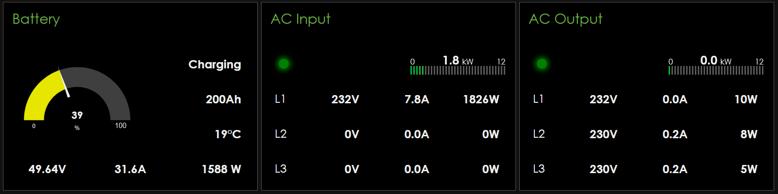
1st picture - L1 only is connected, AC Output - Off, AC Input - 7.8A/1.8kWt, charging - 1.6 kWt, but should be at least 50A/2.5kWt according to spec.


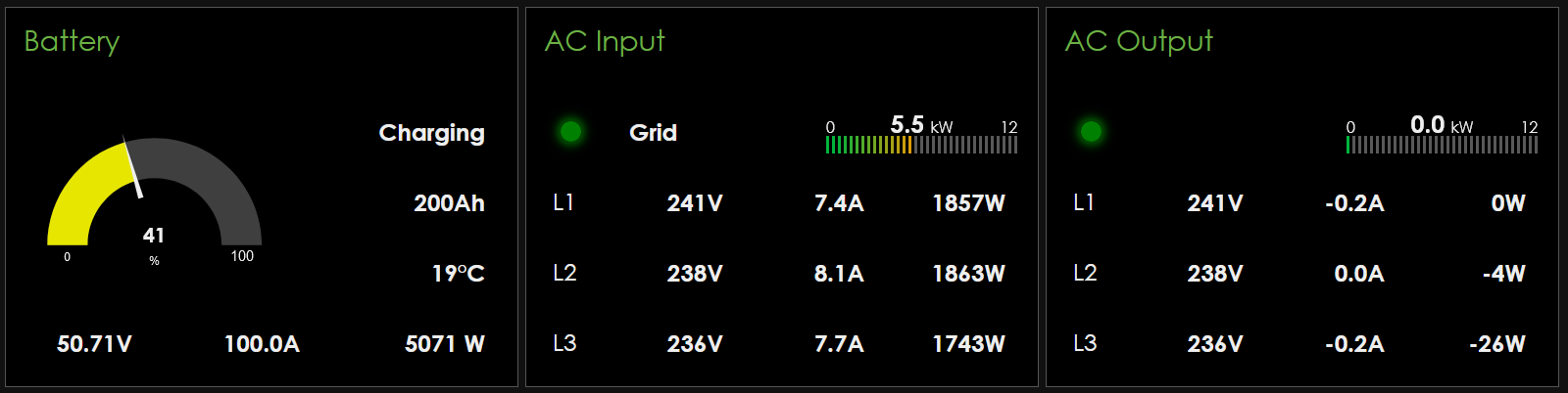
2nd picture - L1/L2/L3 is connected, AC Output - Off, AC Input - ~24A total, charging - 100A/5 kWt as expected.


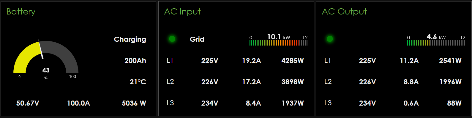
3rd picture - L1/L2/L3 is connected, AC Output - On, AC Input - ~45A/10kWt, charging - 100A/5 kWt as expected. It's just illustration that no problem to get 20A from L1, but only with L2/L3 connected.


So, WDYT?

How to explain such "balance" (?) limit up to 10A, if "physical" real limit for L1 - 25A? Looks as MultiPlus waiting for his/her colleagues and don't want to exceed "virtual" input current dedicated for 3*MultiPlus (8A for L1 and 8A*3 for L1/L2/L3). If it works "as designed", it means that no big sense to connect 1ph Gen to 3Ph, it can't cover all power expenses connected to that system.


1p.png

2p.png

3p.png

Generatorinput current
1p.png (26.3 KiB)
2p.png (26.9 KiB)
3p.png (28.1 KiB)
2 |3000

Up to 8 attachments (including images) can be used with a maximum of 190.8 MiB each and 286.6 MiB total.

2 Answers
Alexandra avatar image
Alexandra answered ·

@OlegV

When you are doing your test with the generator you are only charging at 1826W. I assume that is where your current is set. There are no loads on the AC. Therefore it will not draw more.

When you have all three connected to grid i see the charging watts are around the same.

If you dont have loads and charging that need a 25A input, the system wont pull that from the source

25A at 230v is 5750W on each phase, if weak AC is checked then is will not load the grid. If your input cable is small and has high resistance it will not pull all 25A from grid or generator.

I see the L1 came close to that on the third picture with loads and charging.

4 comments
2 |3000

Up to 8 attachments (including images) can be used with a maximum of 190.8 MiB each and 286.6 MiB total.

olegv avatar image olegv commented ·
Sorry, but I don't understand your answer :(


As said, all these pictures are not related to generator, it's Grid but with L2/L3 disconnected in the 1st case.

My main question is - why if connect only L1, it uses only 1.6 kWt to charge, but not 2.5 kWt as expected? Options: Input Current Limit - 25A, Charge Current - 50A, DVCC Max Charge Current - 100A.


0 Likes 0 ·
Alexandra avatar image Alexandra ♦ olegv commented ·
50A at 50V (battery voltage) is 2500W of charge. If you have weak ac checked then it will not work the charge hard so as to not load the AC connect.

1876W (in first picture) is about 75% of the max target. That is what I would expect to see if weak AC is enabled.

The voltage from all the three phases is different. So again VA (volts multiplied by amps) would then have different amounts.

On your first picture to pull the full 25A from grid, you would need to run a load of 3000W on the AC side, while charging on L1 (but only if weak AC is not enabled) and your cables are correctly dimensioned.


0 Likes 0 ·
olegv avatar image olegv Alexandra ♦ commented ·

Thanks, Weak AC is OFF, it's L1 Grid only.

I don't need 25A from L1 w/o AC Output, but I need ~11A to get full 2.5kWt to charge battery at 50A. In reality It's 8A = 75%. And? Is it intended?

In my understanding, it's the same value as 8A*3=24A for 3ph to get 5kWt to charge battery with max performance. It seems to me, MultiPlus ignores the fact that only 1 phase is connected, and still uses 8A*230V = (100/3)A*48V to charge the battery.

Could you please check your software? Is not it just use "Max Charge Current"/3 instead of real "Charge Current" for 1 connected unit/phase?

0 Likes 0 ·
Alexandra avatar image Alexandra ♦ olegv commented ·
There are many factors that affect charge rate.


Many are install related.

Bms requests

Heat/temperature derating -mentioned in the manual.

Resistance in cables. So could be install related. Both in AC dimensions and in DC dimensions. All if these factors would have to be eliminated first.

Just naming a few.


0 Likes 0 ·
olegv avatar image
olegv answered ·

One more experiment here :)

"Charge Сurrent" is changed for all 3 units - 5A, 10A and 20A accordingly. "DVCC Max Charge Current" - 100A (no change).

Tried to charge, battery current slowly moves from ~5A to ~14A and it's fixed there. Note that phase doesn't matter, all of then use 1.5A. "Charge Сurrent" of concrete unit is ignored, total current seems to be an average: (5+10+20)/3

Seems probably impossible to limit 1-2 phase for charging, they works as one device. No idea - is it good or bad.

5p.png


5p.png (30.7 KiB)
2 |3000

Up to 8 attachments (including images) can be used with a maximum of 190.8 MiB each and 286.6 MiB total.

Related Resources

Additional resources still need to be added for this topic

MultiPlus Generator FAQ

GX - Generator auto start/stop

Automatic Generator start/stop

 Hybrid Generators

Virtual switch - Generator start/stop

Additional resources still need to be added for this topic