question

Stuart avatar image
Stuart asked

Proposed setup but need advice and confirmation on compatibility

Hello all.

Nice to meet you. I have laid out a system but I need clarification on some points. This is my proposed layout................................

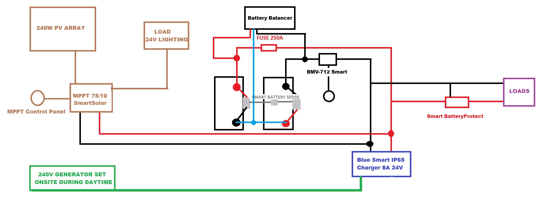
Here are the points I need some clarification on. This layout is using two 420AH 12v batteries, smart battery protect, two smart battery sense bluetooth units, a BMV-712 SOC meter, a battery balancer, Mppt control panel and a blue solar 24V 8A mains charger.


1. Am I able to use two bluetooth smart battery sense modules on one solar controller? If so is the software aware that the batteries are in an array and there are two of them. I cannot find anything in the manuals or datasheets that specifies a limit on the 3M or 10M battery sense modules.


2. I have a Bluesmart charger 24V 8A model. If it is part of the bluetooth ve network and always powered (it will not be) will it start charging when a low battery condition detected or will a have to use the relay on the BMV 712. If so and the answer to my first question is no how will I be able to monitor the temperature of the second battery as using the temperature connection on the BMV-712 or battery connect will create problems. My objective is to wire all the alarm or alert contacts in series to a GSM alarm module.


3. There appears to be some ambiguity regarding the four pin VE Bus. If I am correct the ve bus is a proprietary protocol and individual to only some device types. In other words if you have three bluetooth devices paired to a solar charge controller and then use a ve bus cable to link to a pc or colour control gx none of the data from the bluetooth is passed down the physical interface. I would have expected the solar charge controller to behave as a hub and pass on data. I would like to clarify this.


4. In the above setup I have two physical ve bus port equipped devices. The BMV-712 has one as does the solar charge controller. I also have five bluetooth devices. Is it possible to allow the devices to communicate and if so how. If not am I limited to two devices that have the four pin ve bus connection. I have read everything I can find on manuals and white papers about the ve bus and I do not have an answer. I am surprised that by now there is not a common protocol such as RS485 Modbus or keep to a common proprietary protocol such as ve as it would be the most common protocol used, canbus, nmea and others could then be converted with an adaptor.


I would really appreciate some help and advice as to how to arrange communication on this setup. The ideal scenario would be to have two displays. The battery SOC monitor and the MPPT control panel. I have one or two raspberry pi model B+ boards, is there any benefit to setting up the colour gx system on the pi and connecting the components to that. If there is no way to link these devices together all the parts may just as well have 2 clean relay contacts that could be setup as desired. Ideally I would just like the two meters on display. I would rather not have any bluetooth control or monitoring that the customer would have access to.


Any help, advice and ideas would be fantastic and gratefully received. Thank you for taking the time to read this extended post and my apologies if I have confused ve bus and ve direct.


Many thanks.


Stuart.


chargerBluetoothVE.DirectVE.BusBattery Balancer
5 comments
2 |3000

Up to 8 attachments (including images) can be used with a maximum of 190.8 MiB each and 286.6 MiB total.

klim8skeptic avatar image klim8skeptic ♦ commented ·

Only use 1 smart battery sense, use the bmv712 to monitor battery balance

0 Likes 0 ·
Stuart avatar image Stuart commented ·

hello.

Thanks for the reply but how will I monitor the temperature of battery 2 if I do this.There is that snag and from what I understand this wont adjust charge parameters if the second battery is warmer or colder than the first battery. Will this not cause the two to be charged at a different rate.


Is there a limit of only one smart battery sense on a controler ? If so how will the charge controller and battery charger know that second battery has a problem, come to think of it how will they know battery two has a potential problem and adjust the warmer / colder battery charge rate and even if it did know I cannot see a way for it to adjust the rate for one battery ? Will this not just result in the balancer sitting there chucking away up to one amp of current continuously.


Does anyone know how this can be done or am I using the battery sense in the wrong way ? Could I use a PTC thermistor to lower the current flow into the hotter battery ?


Thanks for your help :-) I may perhaps be using this for the wrong job. I cannot see a way around this aside using independent temperature alarms but by then will damage to the battery not already be done ? If the internal resistance starts changing that is an early warning of pending battery failure AFAIK.


How on earth do people with eight batteries get an early warning of a problem ? I am starting to think this is something that is simply not catered for !


What do you think and thanks for your help :-)


Stuart.


0 Likes 0 ·
Stuart avatar image Stuart Stuart commented ·

I have been reading the manuals for the charge controller, BMV-712 and Smart battery sense.


What I cannot find is a definitive answer for is this.... Am I able to use the bluetooth to communicate from the charge controller to the smart battery sense and the VE.Direct communication port to link from the solar charge controller via cable to the BMV-712 at the same time? If I then use the input on the BMV-712 for midpoint sensing will that alert me to one of the batteries failing?


I will be getting a battery balancer unit to ensure best performance. I know the balancer has an alarm output so I am wondering if I use that to give me early warning will it be enough and will that data be available on the bluetooth screens?


The reason that I want this system with belt and braces on this and as much monitoring and alarms as possible is that I am setting it up for a couple that have a young child that has breathing problems. The ventilator has a 240v power pack that outputs 24VDC on the other side. As it uses 24V DC I can skip using an inverter and save power. The charger is there just in case the solar cant keep up.


This may look a little overkill but if this system fails it could put the child's life at risk. As I will be making a full wiring diagram and then programing it I want to have every angle covered. I don't think I could live with myself if anything went wrong. They may be in some remote places to early warning that the batteries are failing or getting below 50% is absolutely vital.


I have also recommended they purchase a 12V to 24V boost convertor as a backup and will wire the system so any alarms will switch on a changeover relay to the 12V side allowing the alternator on the van to run the ventilator allowing time to get back.


Thanks again all for the help and advice :-)


0 Likes 0 ·

Hello Stuart,

Connecting an MPPT to a BMV-712 with VE.Direct has no function. It is not supported.

In this case, VE.Direct is designed to be connected to a GX device.

You can connect an SmartSolar MPPT to a BMV-712 via bluetooth and a VE.Smart Network.


I am sorry to say after you have taken the time to write all of that, please have a read of the community guidelines; to make the site useful for others also looking for answers, we ask that only a single question be asked per post. That will be the fastest way to get answers.


Please also have a read of this statement.

Life Support Policy

As a general policy, Victron Energy, does not recommend the use of any of its products in life support applications where failure or malfunction of the Victron Energy's product can be reasonably expected to cause failure of the life support device or to significantly affect its safety or effectiveness. Victron Energy does not recommend the use of any of its products in direct patient care. Victron Energy will not knowingly sell its products for use in such applications unless it receives in writing assurances satisfactory to Victron Energy that the risks of injury or damage have been minimized, the customer assumes all such risks, and the Liability of Victron Energy is adequately protected under the circumstances.


0 Likes 0 ·
Stuart avatar image Stuart Guy Stewart (Victron Community Manager) ♦♦ commented ·

Hello Guy


I understand your precautionary action of posting and pointing me towards your disclaimer regarding the use of your products, however your products are sold for leisure use and no claim has been made on any documentation that the products are intended for medical use in your terms of use nor is there any indication that your product designs were intended for use under the European Medical Device Directive (93/42/EEC). Unless you were informed in writing that the equipment was purchased for that use you would not hold any liability for failure under contract law.


Having tendered and signed many business contracts over the years including the purchase order for the BT Redcare (R) infrastructure valued at well over 80 million I am fairly familiar with contract law but I would be happy to supply a non liability waiver if it gave you some reassurance. Any liability would be my sole responsibility.


Many thanks for your information regarding the VE.Bus. I wonder if you would be kind enough to clarify two more questions? If the Blue Smart Charger was also part of the bluetooth VE smart network would the supply need switching via relay or would the VE smart network initialise the charge when the voltage fell below the setpoint. Can I also ask if it is possible to use two battery smart sense V/T modules or is the VE smart network restricted to one only?


Thank you for your reply and I apologise for posting more questions on one post in contradiction to the guidelines. I will ensure I do not repeat the mistake.


Warmest regards


Stuart.


0 Likes 0 ·
3 Answers
Paul B avatar image
Paul B answered ·

Also these questions would be best answered by your local Victron agent

2 |3000

Up to 8 attachments (including images) can be used with a maximum of 190.8 MiB each and 286.6 MiB total.

kai avatar image
kai answered ·

It looks like you're designing a safety critical system. Applicable standards (and really just protecting your PI) may well indicate a need for an independent supervisory system or other suitable controls. I would strongly recommend that you resolve these higher level requirements before looking at specific implementation.


2 |3000

Up to 8 attachments (including images) can be used with a maximum of 190.8 MiB each and 286.6 MiB total.

Stuart avatar image
Stuart answered ·

Thanks for your reply.


I appreciate your concern but I have designed the system from the ground up myself. There is an existing 12v solar system with a DC to DC converter I hand made using gold tolerance and parts that are listed on the MOD electronic procurement list. The Victron setup will be the fourth feed. All of those feeds go into a mosfet switching board and use very high tolerance zener diode's switching off when the avalanche point is met. This is aside from the lithium pack inside the unit itself. I have tapped of the drains of all the mosfets and the supply into the air pumps go into a voltage comparator that latches on a pair of fet's that are aviation grade. The output sounds a 109db piezo sounder with an LED that indicates the failed supply.


The use of all the Victron kit simply gives another stage of protection. Components are RF shielded and conformally coated. The possibility of component failure is very very remote. I do however ensure a system is properly designed even though it is a backup to a backup to err a backup :-D


Thanks for all your input but I have all the parts on my diagram now and the system is functioning even though the battery protect is 0.44 V out from the correct voltage the equipment build quality is excellent. I can see your boards are conformally coated. I do think you should give your pcb design team that laid out the 70/15 charge controller a pay rise. It is a long time since I have seen a board with little space to work with so well laid out.


My only concern is your device security. I personally think as a company you should consider changing from bluetooth to an AES / CCMP wifi communication and encode the password into a QR code ensuring the code to be X/OR'd has high entropy and is of least 30 characters. Aside from that I think the build quality and design is very good.


My only wish is that you had stuck to using something like RS485 M/SS Modbus for all your products. You have many different protocols and types of hardware links. I personally think you should stick to a single interface and protocol. I had a few headaches following interface and protocol types over your product range and data communication security is an area I specialise in so I imagine it could be hard work for someone who is trying to link all your equipment together. A secure serial high speed bus that talks to everything and can be point to point wired would be excellent and the only conversion needed would be to CAN. Making the protocol proprietary and secure is always the way to go.


Aside from the above I am very very happy with the products. If you were to implement a secure comms system for your high end products I would be delighted !


Stuart.


P.S. Mods / Admins - You can close this thread. I have already gone way to of topic and will get my coat !


2 |3000

Up to 8 attachments (including images) can be used with a maximum of 190.8 MiB each and 286.6 MiB total.

Related Resources

VE.Direct protocol FAQ

VictronConnect bluetooth troubleshooting guide

Additional resources still need to be added for this topic

What is VE.Bus?