question

thanar avatar image
thanar asked

V-TAC LFP batteries, trying to source information

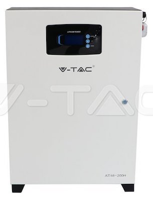
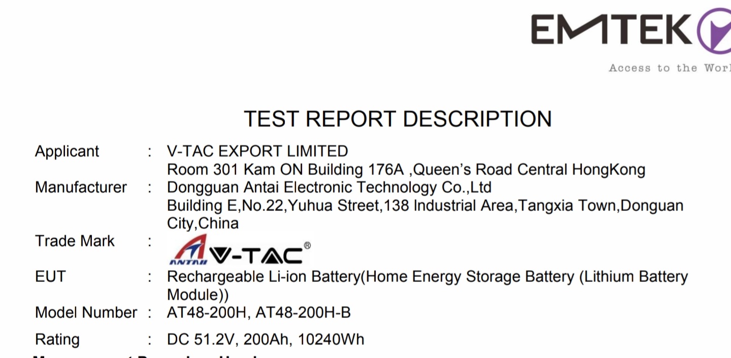
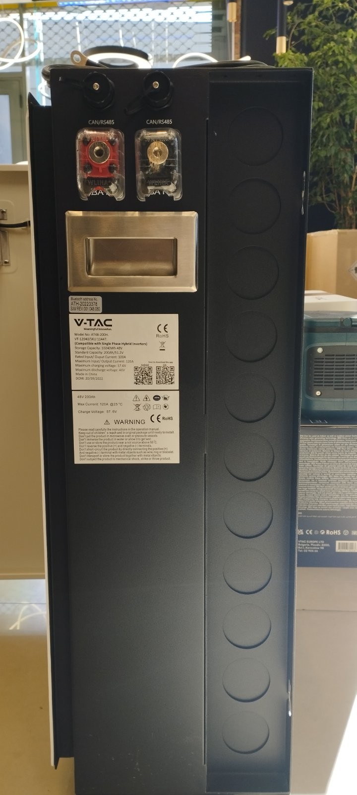
There's a new distributor of LFP batteries in Europe for a couple of months now, under the V-TAC brand. V-TAC was founded some 20 years ago at UAE and has a very strong presence in Europe, particularly eastern Europe and the UK. They've been hard into the LED and lighting business. They've recently started offering LFP batteries for solar projects, along with other energy bundles of dubious quality. I am interested in their 10kWh model (model name: AT48-200H or VT-12040), since I can source them locally for under €250/kWh and they come with a full 5-year warranty.


viber-image-2023-02-02-10-34-29-017.jpg


11447.jpg


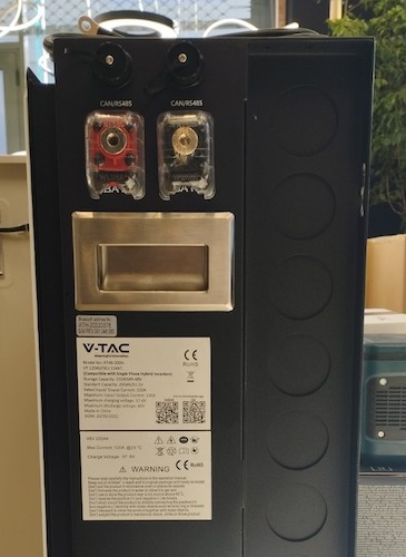
According to the local distributor, the battery is made by Vestwoods, who are a quite well-known producer of batteries, however I haven't seen any in that form factor from them.

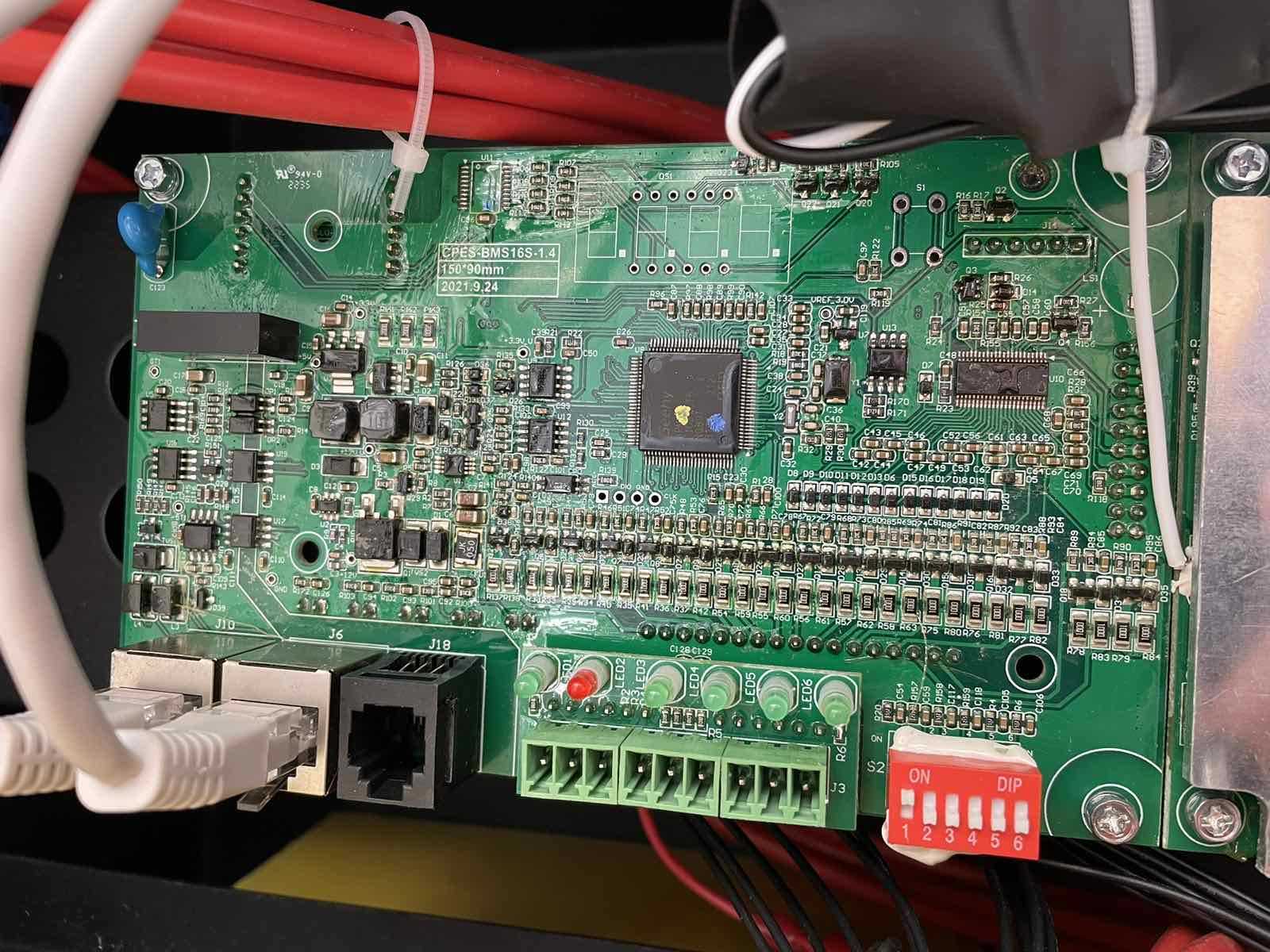
I am trying to figure out the model of their BMS and whether there is any chance of it getting along with an ESS GX setup, either officially or through Louis' excellent serial tool. Here's a photo of the BMS they are using, in case it rings any bells (searching for "CPES-BMS16S" online wouldn't produce any results):


viber-image-2023-02-02-10-34-20-415.jpg


They have published lots of documentation on their website for all models, and there's also a compatibility chart that displays Victron among the compatible brands; it doesn't mention to what extent, though.

I would appreciate any additional information or insights.

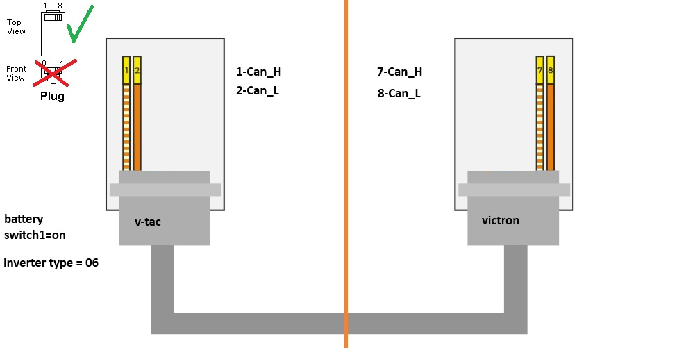
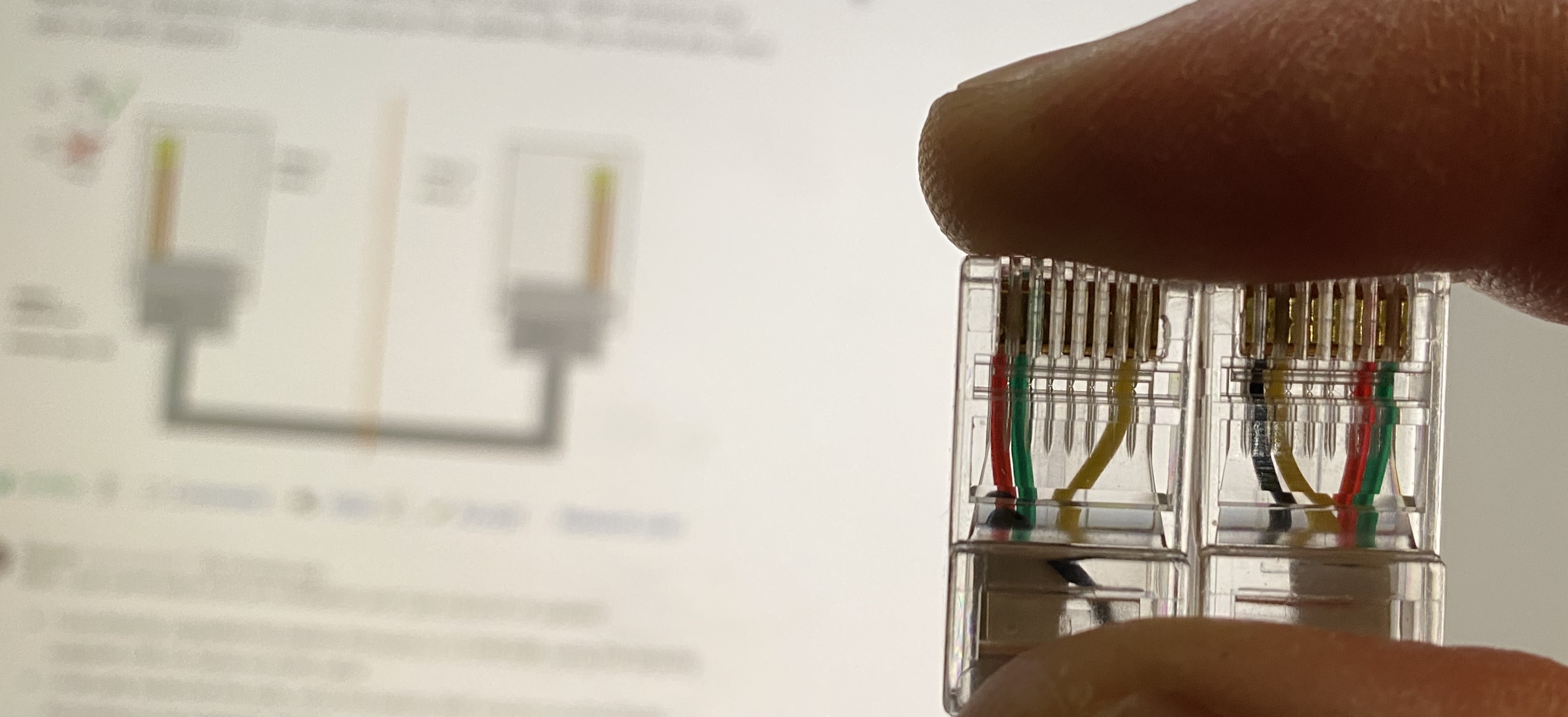
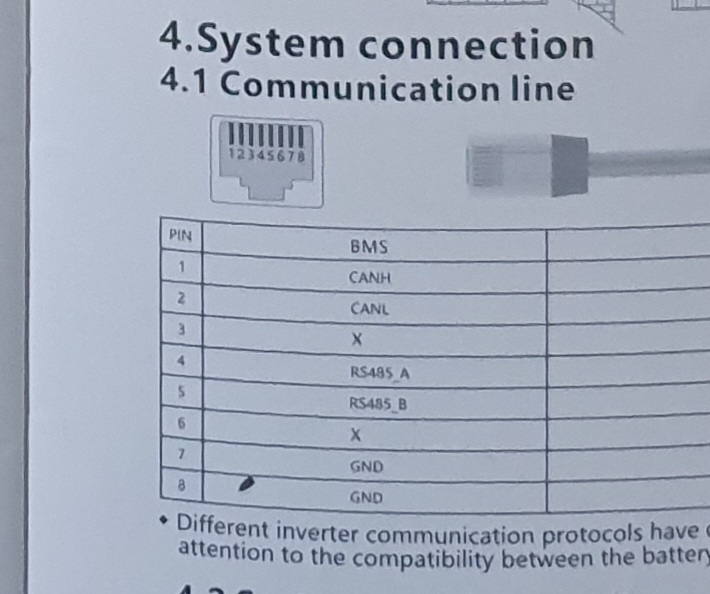
Here's the manual, including communication ports pinout

VT-12040 - manual.pdf


Update [Feb, 2024]:

I have been working with this battery on a zero-feed system for almost a year. There have been a few firmware updates for the battery o far, now running on most recent version (v.1.048.088). I still haven't been able to identify the BMS manufacturer.

Battery seems nicely built, I particularly like the easy access to the cells, which is essential for a yearly manual top balance, since the BMS hasn't been doing a super great job so far (will have to see with the latest firmware version).

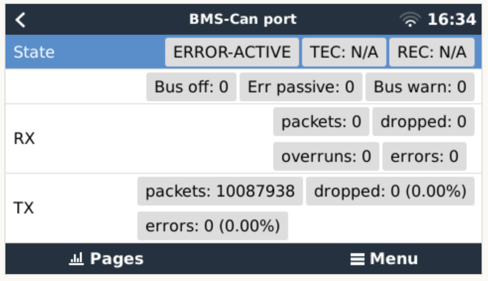
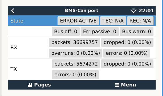
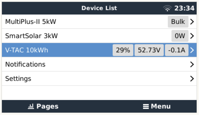
GX connectivity was definitely not trivial, since the directions on the manual were wrong, both for cabling as well as for settings. Please see discussion in this thread for more info. Finally managed to make it work.

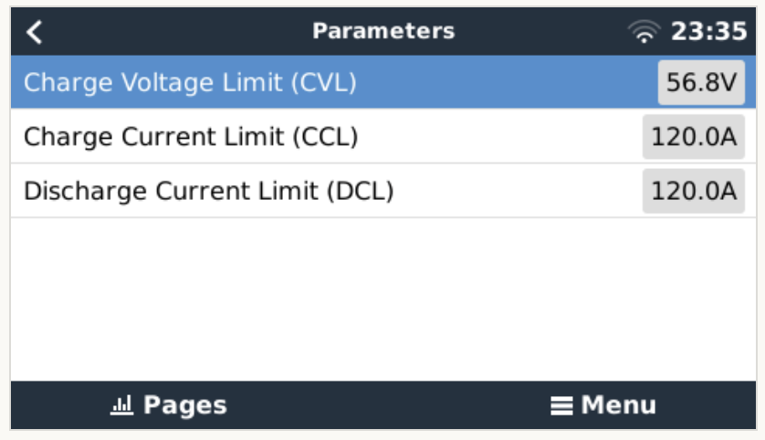
BMS transfers CVL, CCL and DCL values to the GX device, which do work as intended. I'm actually quite pleased with the charging profile the BMS dictates to the System. Have a look at the following graph:

screenshot-2024-02-03-at-180950.png

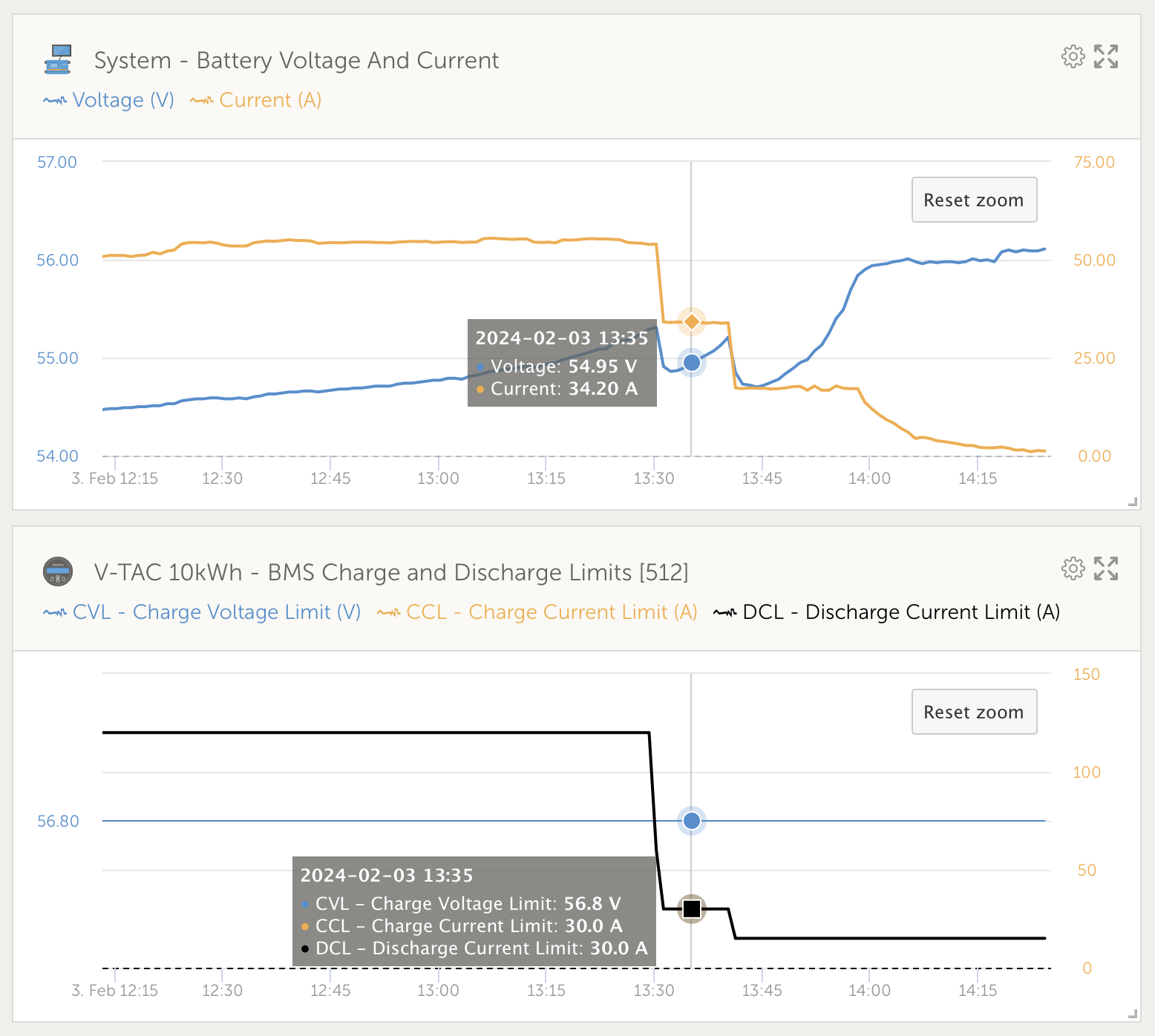
An obvious issue is that the BMS over-reports all currents by about 10%, which is clear at the graph, and has been double-checked using a clamp meter. This results in SoC deviation, which really messes things up. I have only cycled the battery once since installing the latest BMS firmware, maybe it eventually gets hold of the correct values, although I wouldn't bet on it. I should probably get in touch with the manufacturer and ask for a way to calibrate the current readings. If anyone has a way to fiddle with the BMS settings through some software, please chime in below.

Otherwise, GX communications seems to be solid, reversed current flow reported by other users seems to have been corrected, and my battery charges all the way to 100%, although this could be a result of my manual top balancing a few weeks ago.

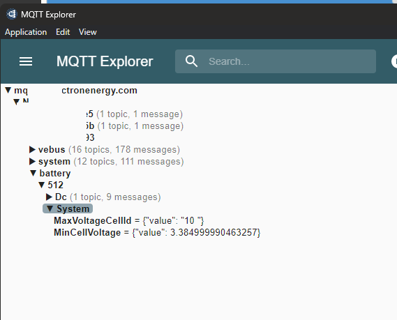
Another thing that's missing from the communication is the min/max cell voltage readings, which are nowhere to be found through the Remote Console.

ESSLithium Batterygx devicebattery suppliers
3 comments
2 |3000

Up to 8 attachments (including images) can be used with a maximum of 190.8 MiB each and 286.6 MiB total.

Tom h avatar image Tom h commented ·

In regards to manufacturer this company: "Dongguan Antai Electronic Technology.." was listed in the test reports. Maybe its worth contacting them for more info also? screenshot-20230414-112456-drive.jpg

0 Likes 0 ·
miroslav avatar image miroslav commented ·

Mám tiež uvedenú batériu a s CCGX mi nekomunikovala. Potom som spravil svoj kábel a začala komunikovať. Prihlásila sa ako LG Resu. BMS to ale pri nabíjaní nepustilo na viac ako 91% SOC. Asi to bude nastavené v BMS. Nemohol som to zmeniť. Ukazovalo to tiež opačne nabíjanie a vybíjanie batérie na CCGX. Mne to fungovalo asi 3 dni. Jedného dňa mi to ale vypísalo komunikačnú chybu a odvtedy mi to zase nekomunikuje. Skúšal som všetko, ale nič nepomáhalo. Bol by som rád, keby mi niekto poradil, čo s tým.

0 Likes 0 ·
thanar avatar image thanar miroslav commented ·
Well, that's interesting. I still haven't got to putting together a custom cable for communication. Could you share the pinout?
0 Likes 0 ·
7 Answers
sawo1337 avatar image
sawo1337 answered ·

Here is the pinout for the cable v-tac - victron. Took me some time to figure out because the manual supplied with the battery is not correct, they are showing front view of the rj45 connector where it needs to be top view otherwise you would be wiring the battery side in reverse. Also make sure that inverter type is 06 and switch 01 is on. After that, connect to the bms-can port of the Cerbo GX and you should see rx/tx packets going both directions immediately. Make sure your firmware is 2023 or newer, older versions may need to be upgraded (v-tac can send you the update file, you would also need usb to rs485 adapter)

rj45-victron-v-tac.jpg

12 comments
2 |3000

Up to 8 attachments (including images) can be used with a maximum of 190.8 MiB each and 286.6 MiB total.

thanar avatar image thanar commented ·

Well, I just came back from an installation and I got a bunch of updates:

  • I successfully upgraded the battery firmware to v.1.048.088, using the recently supplied USB-to-Serial-to-RJ45 cable.
  • I manually balanced the cells, since the battery BMS would cut off at 55.6V. According to my research, cell #2 was too low and I noticed that the BMS is constantly balancing it for an unknown reason, at least according to my IR camera and my clamp meter. Hoping that the newly installed BMS version will fix this issue.
  • After trying for a few hours to set up GX communication, I unfortunately had no luck. The V-TAC documentation is awful, seems like everything regarding communication is upside-down or something. I will be putting together a new cable, following the schematic of this reply. @sawo1337, are you sure the "inverter type" should be set to "06"? Seems like "Victron" gear is "04", according to the manual.
0 Likes 0 ·
sawo1337 avatar image sawo1337 thanar commented ·
@thanar you are right, it should be 04, not sure why I said 06, probably the vtac support team asked me to use that at the time but later on I set it to 04. Let me know if you need any help, I've had to tweak down the voltage as the default lifepo4 values on the victron constantly trigger high cell voltage on the battery bms
0 Likes 0 ·
thanar avatar image thanar sawo1337 commented ·

Triggering cell high voltage disconnect is almost definitely due to an unbalanced battery. I run on the same problem and had to manually balance the battery at the top. Managed to bring the disconnect voltage from 55.6V up to 56.8V so far. That’s the main reason I want to have GX communication, hopefully high voltage would be better managed by the system, by lowering the charge current, thus limiting DC ripple events which should generally be avoided.

1 Like 1 ·
sawo1337 avatar image sawo1337 thanar commented ·

@thanar good point, I should check the battery voltages manually, if I remember correctly, pretty much all batteries were close to eachother, but one was always higher than the rest. I get the high cell voltage alarms even with the cerbo running it, currently at the inverter I have 56.5 absorption and 54.4 float voltage. With these settings it is not as often that I get the alarms, but probably every couple of days.

0 Likes 0 ·
thanar avatar image thanar sawo1337 commented ·
LFP cells have an extremely flat charging curve, you can ONLY check for balancing at over 98%, that's why we only top balance LFP batteries. So, wait for your battery to reach full voltage and then start bringing down the cells with the highest voltages. You can use plain old incandescent lamps attached on crocodile clips with these cells, since all cell terminals are exposed.
0 Likes 0 ·
thanar avatar image thanar commented ·


Looks like I had already reached to the same conclusion regarding the cable pinout. However, upon my earlier tests, this doesn't seem to work for me. Would the ground cable (yellow on the photo, #7 on the battery, #3 on GX) mess things up? Maybe the fact that I am not using a UTP cable, but a rj11 instead?

Upon reading a bit more on termination, looks like I will have to terminate the BMS-CAN bus on the Cerbo side, however still not working with the terminator on.

@stagepower and @andre-godinho, could you have a look at this, please?

img-0990.jpg


0 Likes 0 ·
img-0990.jpg (799.6 KiB)
sawo1337 avatar image sawo1337 thanar commented ·
@thanar no need for the yellow, try using just red and green. Can't say if that's the problem, but it could be as well. Which port are you using on the Cerbo? It has to be BMS-CAN, not VE.CAN or VE.BUS
0 Likes 0 ·
thanar avatar image thanar sawo1337 commented ·

I am connecting to BMS-CAN, however I did not initially terminate the other same port, which I am now reading is mandatory. I just tried with the provided terminator, I also got rid of the yellow line, keeping just the two cables (CAN-H and CAN-L), but still no luck, unfortunately. Any other ideas?

Only thing I haven't tried is setting "Inverter Type" to "06". THIS TURNED OUT TO BE THE CULPRIT.

By the way, why are there that many packets on the TX line on my BMS-CAN?

screenshot-2024-01-28-at-163417.png

0 Likes 0 ·
sawo1337 avatar image sawo1337 thanar commented ·

@thanar glad you've got it sorted! Strange as I have this running as inverter type 04 at the moment, seems like it was set as 06 when I wrote the guide earlier. It would be interesting if you set it to 04 again, maybe it would work as well? Also there should be RX packets, seems like you don't get any? Are you sure it is working? Here is mine, RX is more than TX:1706472262255.png

0 Likes 0 ·
1706472262255.png (26.8 KiB)
thanar avatar image thanar sawo1337 commented ·
I got RX packets now for sure; prior screenshot was before I got it to work...
0 Likes 0 ·
sawo1337 avatar image sawo1337 thanar commented ·

@thanar all normal then, the high TX count prior that was just broadcasts from the cerbo, trying to find something to communicate with.

1 Like 1 ·
thanar avatar image thanar commented ·

Well, what do you know... "Inverter Type" for Victron gear should be "06" for this to work! Yes, the V-TAC documentation is THAT bad!

0 Likes 0 ·
nickdb avatar image
nickdb answered ·
2 |3000

Up to 8 attachments (including images) can be used with a maximum of 190.8 MiB each and 286.6 MiB total.

Tom h avatar image
Tom h answered ·

I just installed 3 of these units.

Managed to come across of this piece of information. img-20230414-wa0006.jpg


1 comment
2 |3000

Up to 8 attachments (including images) can be used with a maximum of 190.8 MiB each and 286.6 MiB total.

thanar avatar image thanar commented ·
Indeed, this info is attached to one of their latest online manuals. Adjusted the inverter code accordingly, but the battery doesn’t talk to the GX device using the provided cable. I will be putting together a type A GX cable and report back.
0 Likes 0 ·
Tom h avatar image
Tom h answered ·

I believe this is the pinout for the BMS. It was in the supplied installation documentation that came with the battery. It includes additional information then what I could find on their website.20230410-093146.jpg


20230410-093146.jpg (98.4 KiB)
1 comment
2 |3000

Up to 8 attachments (including images) can be used with a maximum of 190.8 MiB each and 286.6 MiB total.

sawo1337 avatar image sawo1337 commented ·

Yes, you need just 1 and 2, but make sure to look at the RJ45 connector from the top and not from the front as in this picture.

0 Likes 0 ·
andre-godinho avatar image
andre-godinho answered ·

Hi, I am having the same problem, battery shows reversed amps from the VRM portal, SOC and Voltage works. Adding batteries in parallel also works. You just have to change the address setting in the dip switches.

Mine works on the 02 Inverter code instead of the 04 as stated in their manual.

The original cable does not work, you have to make a corrected cable.

1 comment
2 |3000

Up to 8 attachments (including images) can be used with a maximum of 190.8 MiB each and 286.6 MiB total.

thanar avatar image thanar commented ·

In my case, I should set the “Inverter Type” to “06”, in order to make the battery talk to the GX. How does the battery identify to the GX device in your case? Do you have proper min/max cell voltage readings?

Also, for me the current shows in the correct direction, i.e. not reversed; it is however a bit off, anyone knows of a calibration procedure?

0 Likes 0 ·
Miroslav Todorov avatar image
Miroslav Todorov answered ·

Hi, can someone provide the Victron pin layout so I can make myself a corrected cable. Also which dip switch should I change in order to fix the inverse amps display.

1 comment
2 |3000

Up to 8 attachments (including images) can be used with a maximum of 190.8 MiB each and 286.6 MiB total.

sawo1337 avatar image sawo1337 commented ·
@Miroslav Todorov check my reply below with the pinout.
0 Likes 0 ·
thanar avatar image
thanar answered ·

Finally managed to connect the V-TAC battery to the GX device, by using a cable as mentioned by @sawo1337 on this thread. Careful, "Inverter Type" should be set to "06" and NOT as "04" as per the battery documentation.

Still trying to decide whether it's better to have this battery connected over BMS-CAN, or leave it offline, as I had configured it previously. Will see how the SCS (Shared Current Sense) works at the top in the next couple of days, and make up my mind.

Main reason I wanted the battery connected to the GX was to be able to see the min/max cell voltages. Unfortunately, the battery does NOT share this information to the GX device.

Charge Current Limit (CCL) seems to be working properly, however seems like the Discharge Current Limit also lowers at high SoC which doesn’t make sense.

Also noticing that the current detection of the battery might be a bit off, will have to do additional reasearch.

img-1006.jpeg


img-1006.jpeg (83.0 KiB)
4 comments
2 |3000

Up to 8 attachments (including images) can be used with a maximum of 190.8 MiB each and 286.6 MiB total.

sawo1337 avatar image sawo1337 commented ·

@thanar you can see cell min/max voltage, but not which cell is producing it.
PS. I would be interested about the SCS as well, for me it actually made things worse so I had to turn of DVCC completely.

0 Likes 0 ·
thanar avatar image thanar sawo1337 commented ·

Where exactly do the min/max cell voltages show up? I see no such reading... could you share a screenshot?

screenshot-2024-01-28-at-233414.png

screenshot-2024-01-28-at-233529.png

0 Likes 0 ·
sawo1337 avatar image sawo1337 thanar commented ·

@thanar I'm using MQTT, you can see that via MQTT explorer, I have created custom logging mechanism that stores this data in a database so I can see graphs of it. Depending on how much you want to fiddle with this, you can also create dashboard on your mobile phone to show this data. I have created repo in github with the project, if you're not interesting in logging the data, skip everything but the android app part where I've uploaded the dashboard config. It also has instructions on how to connect to MQTT if you haven't done already - https://github.com/sawo1337/Victron-TIG

Here is the raw mqtt query:
1706535647694.png

0 Likes 0 ·
1706535647694.png (25.3 KiB)
thanar avatar image thanar sawo1337 commented ·
Well, that's quite out of my league, I have only gotten my feet wet on nodeRED so far. Probably such information would be also available though nodeRED, however the installation using the V-TAC battery isn't (yet) running VenusOS (large), so can't test it right away. In any case, I would prefer the min/max cell info through the Remote Console.

Anyway, seems like this isn't my biggest problem, since after connecting the battery to the GX, it looks like the current reading is quite off, by over 20% on some higher draws, which is messing things up a bit. Will have to do some research on the matter and try to find a way to calibrate the current as reported from the BMS...

0 Likes 0 ·