question

panicman avatar image
panicman asked

MultiPlus-II connection with Daly BMS / Daly Interface Board (WNT) via CAN?

Hello Together,

I'm trying since a week or so to connect my MultiPlus-II GX wthy my BMS, which is an Daly 16s 48V 250A BMS. It has communication interface (RS485/CAN) and I set it with the PC-Monitor Software to VICTRONENERGY/CAN. I have also the Daly Interface Board (WNT) that they set to Victron Protocol, as they said, before they send it to me.

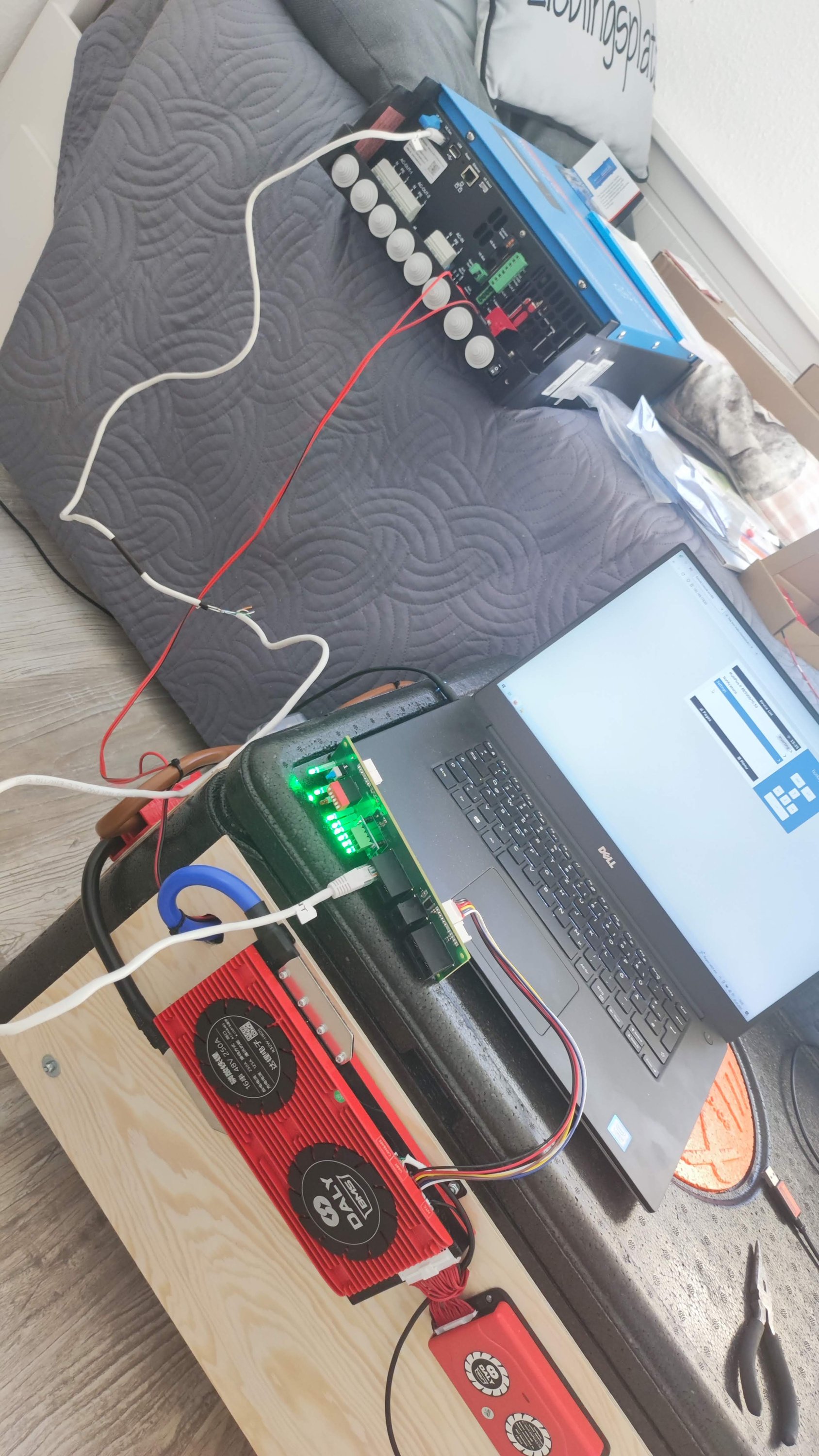
This is how my Setup looks like:

img-20230101-153526.jpg

I also created an customized RJ45 Cable for VE.CAN so they communicate together correctly:
--------------------------------------------------------------------------------------
VE.CAN Side <-> DALY INTERFACE BOARD SIDE
Green/white GND 3 - 3 GND green/white
Brown CAN-L 8 - 4 CAN-L blue
Brown/white CAN-H 7 - 5 CAN-H blue/white
--------------------------------------------------------------------------------------

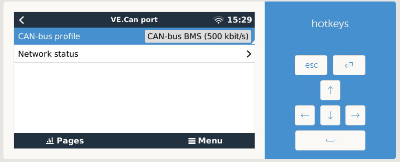
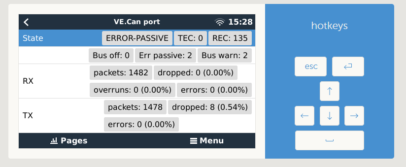
Then I set in the Remote Console the VE.CAN to Other BMS and 500 kbit/s, in the Network status the packets are counting up correctly:

screenshot-3.pngscreenshot-2.png


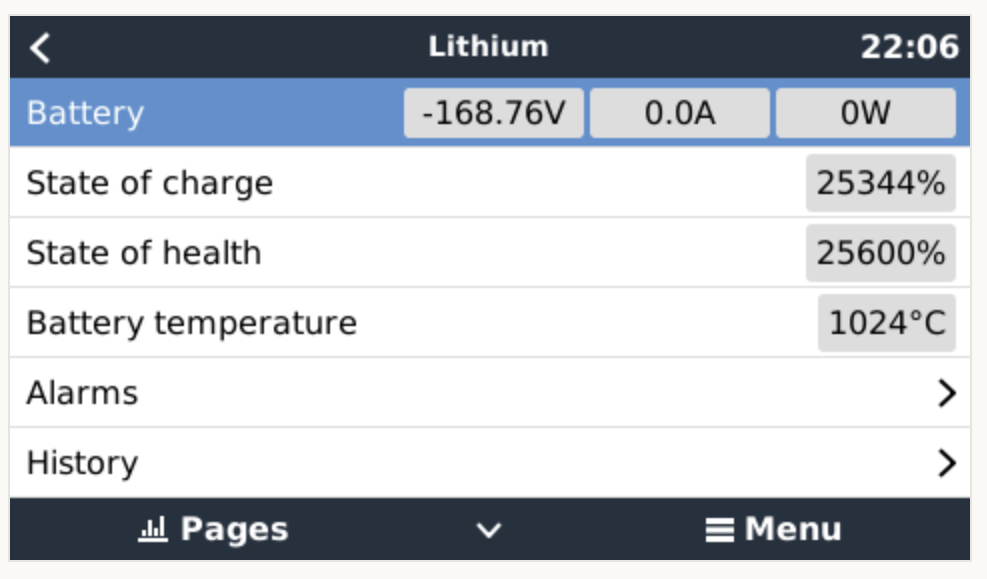
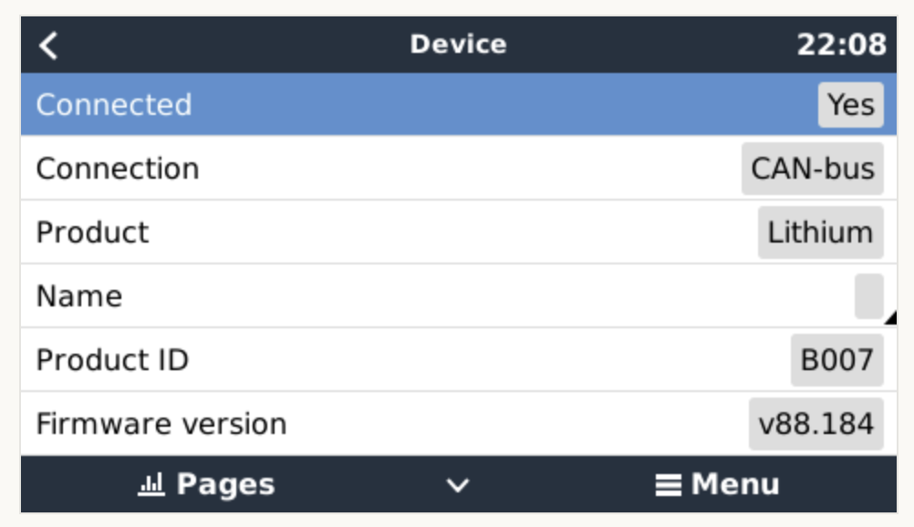
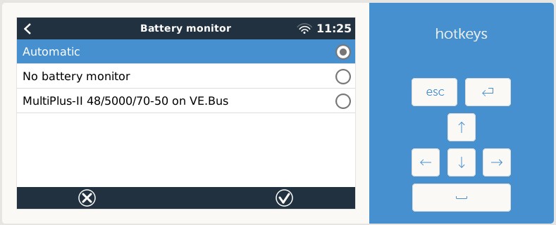
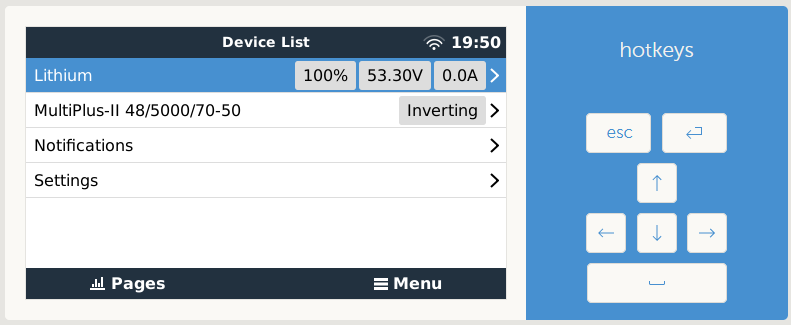
But there is no BMS in the device list or the battery monitor list:

screenshot-16.jpg


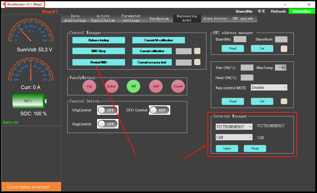
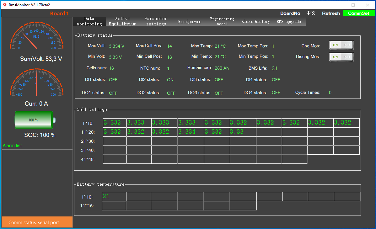
This is how I set up the BMS:

index.jpg


There is an video on youtube where they demonstrate that it is possible:
https://www.youtube.com/watch?v=bUpBq6-WklY

Has anyone managed to connect an Daly BMS to Victron via CAN? What do I need to do to get it work?

Here is the Datasheet of the Daly Interface Board (WNT):
DL-WNT-V1.0 datasheet of collection board.docx.pdf


Greetings Jack

Multiplus-IIBMSVE.Can
2 |3000

Up to 8 attachments (including images) can be used with a maximum of 190.8 MiB each and 286.6 MiB total.

6 Answers
panicman avatar image
panicman answered ·

After an great hint from an other Forum I have now the solution why it was not working. So here is the Solution:

  1. Set all the DIP-Spwitches on the Interface Board (WNT) down to OFF.
  2. Now you can connect with the PC Software to it via RS485 and read out the settings of the WNT: 1673290467736.png
  3. In the Engineering Model Tab set the Inverter to VICTRON+CAN, in my case it was set to VOLTRONICS+CAN, after I set it to VICTRON+CAN it was visible in the MP2:1673290241682.png

Now, the last thing what I have is, after I set the BMS as the Battery Monitor, I get an Low Voltage Error: 1673291792117.png
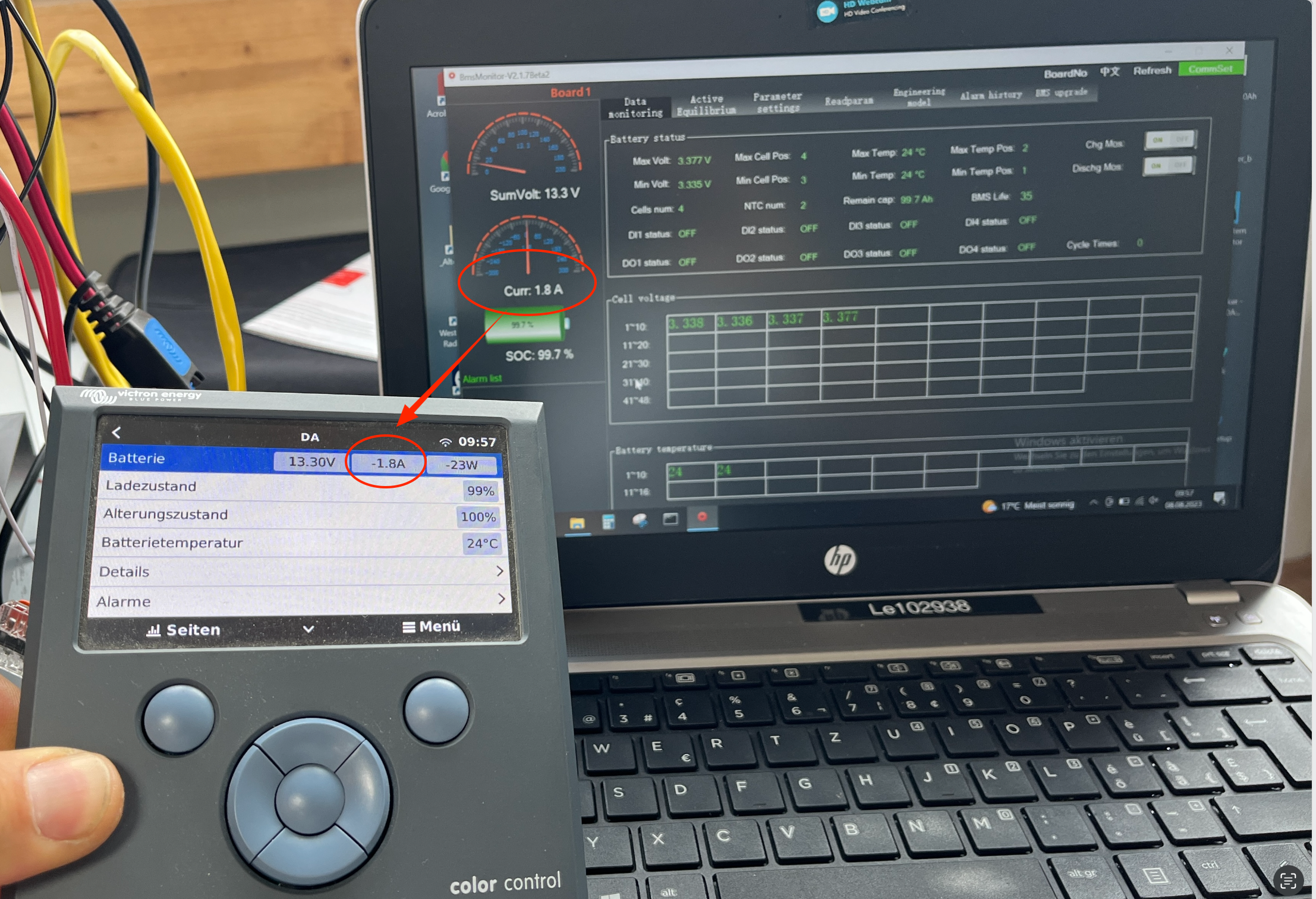
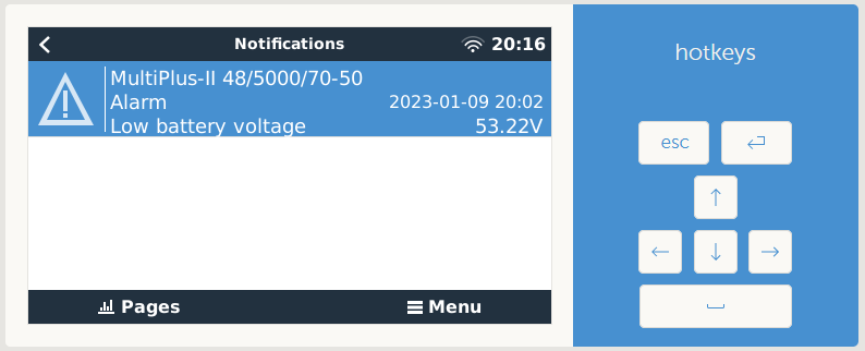
Any Idea why? I checked all the Settings, the BMS has no Errors, so the Error came from the Victron, I checked all the Voltage settings, I have absoluely no Idea why it came at 53.22V, has anyone an Idea?

Greetings Jack


1673290467736.png (103.2 KiB)
1673290241682.png (29.3 KiB)
1673291792117.png (30.2 KiB)
2 |3000

Up to 8 attachments (including images) can be used with a maximum of 190.8 MiB each and 286.6 MiB total.

tochal avatar image
tochal answered ·

hi,

how about changing the setting to see if the error disappears at all , i mean just for trouble shooting, change the under-voltage limit to 1-2 volts lower ( for example 50V) and see if the Error disappears at all !!

if yes, then increase it slowly until error appears again , then you can set a new level , ( if the new level is still acceptable )

5 comments
2 |3000

Up to 8 attachments (including images) can be used with a maximum of 190.8 MiB each and 286.6 MiB total.

panicman avatar image panicman commented ·
Undervoltage is set in the ESS to all C-Loads to 46V, Sustain Voltage set to 48V. I have no Idea how it should happen that it shows that message. Anyway, that happens only once and since then not again. I will look if this happens again.
0 Likes 0 ·
Andy avatar image Andy panicman commented ·
The undervoltage message is not coming from the MP or Victron, I believe. Check these settings in the Daly and maybe change them a bit to see if this makes a difference. The MP only shows what the Daly sends via CAN is my assumption.
1 Like 1 ·
tochal avatar image tochal panicman commented ·
HI panicman, how does it look like? have you got Err Msg again or it is fine now?
0 Likes 0 ·
panicman avatar image panicman tochal commented ·
Nope, did not appear again until now. But we have lost the Sun here for about two weeks, so the Battery is all the Time at ~20% SOC, still on the first cycle. I hate Winters like that...
0 Likes 0 ·
tochal avatar image tochal panicman commented ·
the same here. hahaaa, but i like winter , in winter we can ski.

then may be the reason that you didnt get over voltage Err, is that you didnt reach the voltage. soon or late, sun will appear.

please keep us informed about it. i learned a lot from your post.

thanks and regards


1 Like 1 ·
xf2334 avatar image
xf2334 answered ·

Hi Panicman,

I've the same setup as you. I've set the BMS to Victronenergy/CAN by BMSMonitor Software, like you suggested. But still I get the nonsense values shown. Did you made any other changes that you maybe not mentioned here?


1673989644950.png

1673989723497.png


1673989644950.png (75.7 KiB)
1673989723497.png (68.6 KiB)
4 comments
2 |3000

Up to 8 attachments (including images) can be used with a maximum of 190.8 MiB each and 286.6 MiB total.

panicman avatar image panicman commented ·
Not that I know. Did you connect the BMS directly to the Victron or through the Interface Board? Did you change correctly to VICTRONENERGY/CAN? Because there is an entry for VICTRON/CAN too, but no Idea what it is for... Set it in the Interface Board AND the BMS. Also check the BMS setting in the Victron is set to CAN BMS 500kbps.
0 Likes 0 ·
xf2334 avatar image xf2334 panicman commented ·
yes, did all the same like you. but 1 difference: I did set can mode in wnt only. Will try to set it in the BMS itself tomorrow.
0 Likes 0 ·
xf2334 avatar image xf2334 xf2334 commented ·
@PanicMan how did you set CAN at the BMS? With the iphone app, I can set VictronEnergy/CAN, insert Pin 123456 and it looks good in the first place, but when I read the settings again it flips back to None/RS485. Also Restarting/Resetting doesn't help.

The WNT shows a correct setting Victronenergy/Can, when I read out by RS485 with BMSMonitor Software.

But still, I get bad readings by venus gx. When I unplug/plug the can bus, it is detected instantly, but the readings are mostly garbage.

0 Likes 0 ·
panicman avatar image panicman xf2334 commented ·

It was the same for me with that flip back. I set the inverter in the BMS with the same BMSMonitor Software as for the WNT, different connection Cable. Nothing else.

How is the CAN Packet Monitor looks like? Maybe it is because of the venus, did you tried that in an cerbo? I used it in MP2 GX directly.


0 Likes 0 ·
jolilo avatar image
jolilo answered ·

hello panicman

great post

can you give us a diagram of the cable you made for the VE.CAN Side connection <-> DALY INTERFACE BOARD SIDE

is the base a straight or crossed rj45

Do you have a download link for v2.17!

I only found a 2.16

is the cable between the WNT and BMS supplied with the WNT

Cordially

2 comments
2 |3000

Up to 8 attachments (including images) can be used with a maximum of 190.8 MiB each and 286.6 MiB total.

panicman avatar image panicman commented ·

Base is an straight rj45, not supplied with the WNT:

VE.CAN Side <-> DALY INTERFACE BOARD SIDE
Green/white GND 3 - 3 GND green/white
Brown CAN-L 8 - 4 CAN-L blue
Brown/white CAN-H 7 - 5 CAN-H blue/white

1675691696001.png

https://diysolarforum.com/threads/daly-bms-make-communication-with-victron-energy-via-interface-board.49636/post-685618

0 Likes 0 ·
1675691696001.png (282.7 KiB)
jolilo avatar image
jolilo answered ·

Merci ! ,THANKS.

2 |3000

Up to 8 attachments (including images) can be used with a maximum of 190.8 MiB each and 286.6 MiB total.

djdemond avatar image
djdemond answered ·

Have not got very far with this. I am using venus OS on RPI. I have a Canable pro USB adaptor which works and shows the can0 interface in the Services menu in remote console. This has been flashed with Candlelight firmware successfully and works in windows when tested - it shows in device manager and the data can be monitored via Cangeroo software.

I have DalyBMS 250A 16S LiFePO4 which has been working flawlessly for 6 months now.

I have the Daly WNT interface board, which I specified for Victron when ordering.

When I connect the WNT board to the BMS, the LEDs light up and the relay switches. The first green LED is flashing slowly.

I have made up a CAN cable using pin 3 GND, 4 blue, 5 Blue/white from the RJ45 on the daily interface board to GND, L, H on the canable adaptor.

One question canable has a jumper option for termination with built-in 120 ohm resistor. Does the interface have this termination built in?

I have connected the CAN cable to the Canable adaptor to the RPI via USB.

I am using the latest version of PCmaster software to monitor/control the daily BMS. I set "victron energy" and "CAN" in PCmaster Engineering model tab- inverter manager box. I hit reset BMS.

However there is no can data being sent, either monitoring with remote console or by connecting the canable to windows and looking at the can data.

Do I need to flash my BMS these are the version numbers?1679314327838.png If so does anyone have the firmware or know where to get it?


1679314327838.png (140.3 KiB)
2 |3000

Up to 8 attachments (including images) can be used with a maximum of 190.8 MiB each and 286.6 MiB total.